ICGOO在线商城 > 集成电路(IC) > PMIC - 栅极驱动器 > MIC4127YME
/MIC4127YME.jpg)
 Datasheet下载
- 型号: MIC4127YME
- 制造商: Micrel
- 库位|库存: xxxx|xxxx
- 要求:
| 数量阶梯 | 香港交货 | 国内含税 |
| +xxxx | $xxxx | ¥xxxx |
查看当月历史价格
查看今年历史价格
MIC4127YME产品简介:
ICGOO电子元器件商城为您提供MIC4127YME由Micrel设计生产,在icgoo商城现货销售,并且可以通过原厂、代理商等渠道进行代购。 MIC4127YME价格参考。MicrelMIC4127YME封装/规格:PMIC - 栅极驱动器, Low-Side Gate Driver IC Non-Inverting 8-SOIC-EP。您可以下载MIC4127YME参考资料、Datasheet数据手册功能说明书,资料中有MIC4127YME 详细功能的应用电路图电压和使用方法及教程。
MIC4127YME 是 Microchip Technology 公司推出的一款栅极驱动器,属于电源管理集成电路(PMIC)中的栅极驱动器类别。该器件主要用于高效驱动功率MOSFET或IGBT等开关元件。

应用场景包括:

1. DC-DC转换器:适用于高频率、高效率的升压或降压电源设计,常见于通信设备、工业控制系统和嵌入式系统中。

2. 电机驱动电路:用于驱动直流电机、步进电机或无刷电机的H桥电路,广泛应用于自动化设备、机器人及电动工具中。

3. 电源逆变器:在UPS(不间断电源)、太阳能逆变器以及电动车电驱系统中,MIC4127YME可用于控制功率管的快速开关,提高能量转换效率。

4. 负载开关与热插拔应用:适用于服务器、存储设备和电信设备中对电源进行快速、可控切换的场合。

5. 同步整流电路:提升电源系统的整体效率,特别适合低电压大电流输出的应用场景。

该芯片具备较强的驱动能力和良好的抗干扰性能,适合在高温和严苛环境下稳定工作,是一款适用于多种功率电子系统的高性能解决方案。
| 参数 | 数值 |
| 产品目录 | 集成电路 (IC)半导体 |
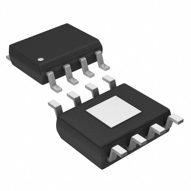
| 描述 | IC DRIVER MOSFET 1.5A DUAL 8SOIC门驱动器 1.5A Dual High Speed MOSFET Driver with Low Thermal Impedance (Pb-Free) |
| 产品分类 | PMIC - MOSFET,电桥驱动器 - 外部开关集成电路 - IC |
| 品牌 | Micrel |
| 产品手册 | |
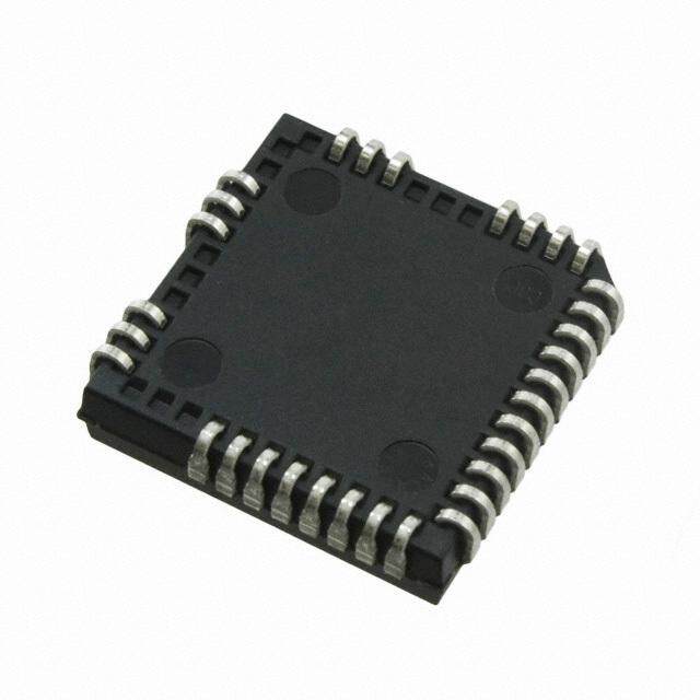
| 产品图片 |
|
| rohs | 符合RoHS无铅 / 符合限制有害物质指令(RoHS)规范要求 |
| 产品系列 | 电源管理 IC,门驱动器,Micrel MIC4127YME- |
| 数据手册 | |
| 产品型号 | MIC4127YME |
| PCN组件/产地 | |
| 上升时间 | 13 ns |
| 下降时间 | 15 ns |
| 产品 | MOSFET Gate Drivers |
| 产品目录页面 | |
| 产品种类 | 门驱动器 |
| 供应商器件封装 | 8-SOIC-EP |
| 其它名称 | 576-1186 |
| 包装 | 管件 |
| 商标 | Micrel |
| 安装类型 | 表面贴装 |
| 安装风格 | SMD/SMT |
| 封装 | Tube |
| 封装/外壳 | 8-SOIC(0.154",3.90mm 宽)裸焊盘 |
| 封装/箱体 | SOIC-8 |
| 工作温度 | -40°C ~ 125°C |
| 工厂包装数量 | 95 |
| 延迟时间 | 37ns |
| 最大工作温度 | + 125 C |
| 最小工作温度 | - 40 C |
| 标准包装 | 95 |
| 激励器数量 | 2 |
| 电压-电源 | 4.5 V ~ 20 V |
| 电流-峰值 | 1.5A |
| 电源电压-最大 | 20 V |
| 电源电压-最小 | 4.5 V |
| 电源电流 | 1.4 mA |
| 类型 | Dual Low-Side MOSFET Driver |
| 系列 | MIC4127 |
| 输入类型 | 非反相 |
| 输出数 | 2 |
| 输出电流 | 1.5 A |
| 输出端数量 | 2 |
| 配置 | Dual Non-Inverting |
| 配置数 | 2 |
| 高压侧电压-最大值(自举) | - |


- 商务部:美国ITC正式对集成电路等产品启动337调查
- 曝三星4nm工艺存在良率问题 高通将骁龙8 Gen1或转产台积电
- 太阳诱电将投资9.5亿元在常州建新厂生产MLCC 预计2023年完工
- 英特尔发布欧洲新工厂建设计划 深化IDM 2.0 战略
- 台积电先进制程称霸业界 有大客户加持明年业绩稳了
- 达到5530亿美元!SIA预计今年全球半导体销售额将创下新高
- 英特尔拟将自动驾驶子公司Mobileye上市 估值或超500亿美元
- 三星加码芯片和SET,合并消费电子和移动部门,撤换高东真等 CEO
- 三星电子宣布重大人事变动 还合并消费电子和移动部门
- 海关总署:前11个月进口集成电路产品价值2.52万亿元 增长14.8%


PDF Datasheet 数据手册内容提取
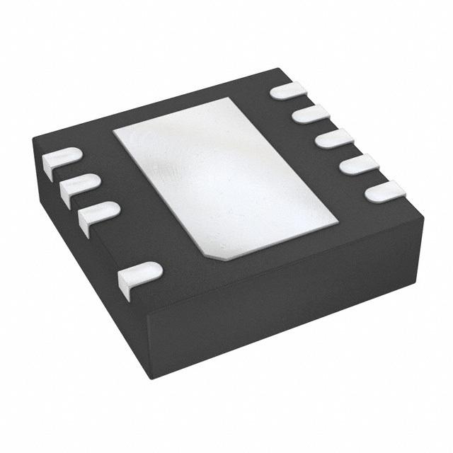
MIC4126/27/28 Dual 1.5A-Peak Low-Side MOSFET Drivers in Advanced Packaging General Description Features The MIC4126, MIC4127, and MIC4128 family are highly- • Dual 1.5A-peak drivers reliable dual 1.5A low-side MOSFET drivers fabricated on • 4.5V to 20V operating range Micrel’s BiCMOS/DMOS process. The devices feature low • Exposed backside pad packaging reduces heat power consumption and high efficiency. The MIC4126/27/28 translate TTL or CMOS input logic levels to – ePAD SOIC-8L (θJA = 58°C/W) output voltage levels that swing within 25mV of the positive – ePAD MSOP-8L (θ = 60°C/W) JA supply or ground whereas comparable bipolar devices are – 3mm x 3mm MLF™-8L (θ = 60°C/W) JA capable of swinging only to within 1V of the supply. The • Bipolar/CMOS/DMOS construction MIC4126/7/8 is available in three configurations: dual – 25mV maximum output offset from supply or ground inverting, dual non-inverting, and complimentary output. • Latch-up protection to >200mA reverse current The MIC4126/27/28 offer pin-compatible as well as smaller footprint replacements for the MIC4426/27/28 with • Switches 1000pF in 25ns improved packaging and electrical performance. The • Logic-input threshold independent of supply voltage MIC4126/27/28 are available in exposed pad, EPAD, • Logic-input protection to –5V SOIC-8L and MSOP-8L options as well as a small-size • 6pF typical equivalent input capacitance 3mm x 3mm MLF™-8L option. The devices have an input operating range of 4.5V to 20V. • Dual inverting, dual non-inverting, and complementary configurations Primarily intended for driving power MOSFETs, MIC4426/7/8 drivers are suitable for driving other loads • -40°C to +125°C operating junction temperature range (capacitive, resistive, or inductive) which require low- Applications impedance, high peak current, and fast switching time. The devices can withstand up to 500mA of reverse current • DC/DC converters (either polarity) without latching and up to 5V noise spikes • Motor drivers (either polarity) on ground pins. • Clock line driver Data sheets and support documentation can be found on Micrel’s web site at www.micrel.com. Functional Diagram MIC4126/27/28 Block Diagram MicroLeadFrame and MLF are registered trademarks of Amkor Technology, Inc, Inc. Micrel, Inc. • 2180 Fortune Drive • San Jose, CA 95131 • USA • tel +1(408) 944-0800 • fax +1(408) 474-1000 • http://www.micrel.com July 2005 M9999-072605 (408) 955-1690
Micrel MIC4126/27/28 Ordering Information Part Number Configuration Package Junction Temp. Range(1) Lead Finish MIC4126YME Dual Inverting EPAD 8-lead SOIC –40° to +125°C Pb-Free MIC4126YMME Dual Inverting EPAD 8-lead MSOP –40° to +125°C Pb-Free MIC4126YML Dual Inverting 8-lead MLF –40° to +125°C Pb-Free MIC4127YME Dual Non-inverting EPAD 8-lead SOIC –40° to +125°C Pb-Free MIC4127YMME Dual Non-inverting EPAD 8-lead MSOP –40° to +125°C Pb-Free MIC4127YML Dual Non-inverting 8-lead MLF –40° to +125°C Pb-Free MIC4128YME Inverting + Non-inverting EPAD 8-lead SOIC –40° to +125°C Pb-Free MIC4128YMME Inverting + Non-inverting EPAD 8-lead MSOP –40° to +125°C Pb-Free MIC4128YML Inverting + Non-inverting 8-lead MLF –40° to +125°C Pb-Free Pin Configuration EPAD SOIC-8L (ME) EPAD SOIC-8L (ME) EPAD SOIC-8L (ME) EPAD MSOP-8L (MME) EPAD MSOP-8L (MME) EPAD MSOP-8L (MME) MLF-8L (ML) MLF-8L (ML) MLF-8L (ML) Pin Description Pin Number Pin Name Pin Function 1, 8 NC Not internally connected 2 INA Control Input A: TTL/CMOS compatible logic input 3 GND Ground 4 INB Control Input B: TTL/CMOS compatible logic input. 5 OUTB Output B: CMOS totem-pole output. 6 V Supply Input: +4.5V to +20V S 7 OUTA Output A: CMOS totem-pole output. EP GND Ground, backside pad. July 2005 2 M9999-072605 (408) 955-1690
Micrel MIC4126/27/28 Absolute Maximum Ratings (1) Operating Ratings (2) Supply Voltage (V )......................................................+24V Supply Voltage (V )......................................+4.5V to +20V S S Input Voltage (V )...........................V + 0.3V to GND – 5V Temperature Range (T )...........................–40°C to +125°C IN S J Junction Temperature (T ).........................................150°C Package Thermal Resistance J 3X3 MLF™ θ .................................................60°C/W Storage Temperature................................–65°C to +150°C JA EPAD MSOP-8L θ ...............................60°C/W Lead Temperature (10 sec.)......................................300°C JA EPAD SOIC-8L θ .................................58°C/W ESD Rating, Note 3 JA Electrical Characteristics (4) 4.5V ≤ V ≤ 20V; Input voltage slew rate >1V/µs; C = 1000pF. T = 25°C, bold values indicate full specified temperature range; S OUT A unless noted. Symbol Parameter Condition Min Typ Max Units Input V Logic 1 Input Voltage 2.4 1.4 IH V 2.4 1.6 V Logic 0 Input Voltage 1.1 0.8 IL V 1.3 0.8 IIN Input Current 0 ≤ VIN ≤ VS –1 1 µA Output V High Output Voltage V–0.025 V OH S V Low Output Voltage 0.025 V OL R Output Resistance I = 10mA, V = 20V 6 10 O OUT S Ω 8 12 I Peak Output Current 1.5 A PK I Latch-Up Protection Withstand reverse current >200 mA Switching Time t Rise Time Test Figure 1 13 30 R ns 20 40 t Fall Time Test Figure 1 15 25 F ns 18 40 t Delay Time Test Figure 1 37 50 D1 ns 43 60 t Delay Time Test Figure 1 40 60 D2 ns 45 70 Power Supply I Power Supply Current V = V = 3.0V 1.4 4.5 S INA INB mA 1.5 8 I Power Supply Current V = V = 0.0V 0.18 0.4 S INA INB mA 0.19 0.6 Notes: 1. Exceeding the absolute maximum rating may damage the device. 2. The device is not guaranteed to function outside its operating rating. 3. Devices are ESD sensitive. Handling precautions recommended. Human body model: 1.5kΩ in series with 100pF. 4. Specification for packaged product only. July 2005 3 M9999-072605 (408) 955-1690
Micrel MIC4126/27/28 Test Circuit Figure 1a. Inverting Configuration Figure 2a. Non-inverting Configuration Figure 2b. Non-inverting Timing Figure 1b. Inverting Timing July 2005 4 M9999-072605 (408) 955-1690
Micrel MIC4126/27/28 Typical Characteristics July 2005 5 M9999-072605 (408) 955-1690
Micrel MIC4126/27/28 Application Information for total power dissipation is the sum of the dissipation caused by the load and the transition power dissipation (P L Supply Bypassing + P ). T Large currents are required to charge and discharge large Load Dissipation capacitive loads quickly. For example, changing a 1000pF load by 16V in 25ns requires 0.8A from the supply input. Power dissipation caused by continuous load current (when driving a resistive load) through the driver’s output To guarantee low supply impedance over a wide frequency resistance is: range, parallel capacitors are recommended for power supply bypassing. Low-inductance ceramic MLC capacitors P = I 2 R L L O with short lead lengths (< 0.5") should be used. A 1.0µF For capacitive loads, the dissipation in the driver is: film capacitor in parallel with one or two 0.1µF ceramic MLC capacitors normally provides adequate bypassing. P = f C V 2 L L S Grounding Transition Dissipation When using the inverting drivers in the MIC4126 or In applications switching at a high frequency, transition MIC4128, individual ground returns for the input and output power dissipation can be significant. This occurs during circuits or a ground plane are recommended for optimum switching transitions when the P-channel and N-channel switching speed. The voltage drop that occurs between the output FETs are both conducting for the brief moment driver’s ground and the input signal ground, during normal when one is turning on and the other is turning off. high-current switching, will behave as negative feedback P = 2 f V Q and degrade switching speed. T S Charge (Q) is read from the following graph: The E-pad and MLF packages have an exposed pad under the package. It’s important for good thermal performance that this pad is connected to a ground plane. Control Input Unused driver inputs must be connected to logic high (which can be V ) or ground. For the lowest quiescent S current (< 500µA), connect unused inputs-to-ground. A logic-high signal will cause the driver to draw up to 9mA. The control input voltage threshold is approximately 1.5V. The control input recognizes 1.5V up to V as a logic high S and draws less than 1µA within this range. Power Dissipation Power dissipation should be calculated to make sure that Crossover Energy Loss per Transition the driver is not operated beyond its thermal ratings. Quiescent power dissipation is negligible. A practical value July 2005 6 M9999-072605 (408) 955-1690
Micrel MIC4126/27/28 Package Information 8-Pin Exposed Pad SOIC (M) 8-Pin Exposed Pad MSOP (MM) July 2005 7 M9999-072605 (408) 955-1690
Micrel MIC4126/27/28 8-Pin MLF (ML) MICREL, INC. 2180 FORTUNE DRIVE SAN JOSE, CA 95131 USA TEL +1 (408) 944-0800 FAX +1 (408) 474-1000 WEB http:/www.micrel.com The information furnished by Micrel in this data sheet is believed to be accurate and reliable. However, no responsibility is assumed by Micrel for its use. Micrel reserves the right to change circuitry and specifications at any time without notification to the customer. Micrel Products are not designed or authorized for use as components in life support appliances, devices or systems where malfunction of a product can reasonably be expected to result in personal injury. Life support devices or systems are devices or systems that (a) are intended for surgical implant into the body or (b) support or sustain life, and whose failure to perform can be reasonably expected to result in a significant injury to the user. A Purchaser’s use or sale of Micrel Products for use in life support appliances, devices or systems is a Purchaser’s own risk and Purchaser agrees to fully indemnify Micrel for any damages resulting from such use or sale. © 2004 Micrel, Incorporated. July 2005 8 M9999-072605 (408) 955-1690
Mouser Electronics Authorized Distributor Click to View Pricing, Inventory, Delivery & Lifecycle Information: M icrel: MIC4127YMME TR MIC4128YMME TR MIC4127YML TR M icrochip: MIC4126YMME MIC4126YME MIC4127YMME MIC4128YMME MIC4128YME MIC4127YME MIC4127YME-TR MIC4128YML-TR MIC4128YMME-TR MIC4127YML-TR MIC4127YMME-TR MIC4128YME-TR MIC4126YMME-TR MIC4126YME-TR MIC4126YML-TR