ICGOO在线商城 > 集成电路(IC) > PMIC - 配电开关,负载驱动器 > MIC2544-2YM
/MIC2544-2YM.jpg)
 Datasheet下载
- 型号: MIC2544-2YM
- 制造商: Micrel
- 库位|库存: xxxx|xxxx
- 要求:
| 数量阶梯 | 香港交货 | 国内含税 |
| +xxxx | $xxxx | ¥xxxx |
查看当月历史价格
查看今年历史价格
MIC2544-2YM产品简介:
ICGOO电子元器件商城为您提供MIC2544-2YM由Micrel设计生产,在icgoo商城现货销售,并且可以通过原厂、代理商等渠道进行代购。 MIC2544-2YM价格参考¥8.85-¥11.07。MicrelMIC2544-2YM封装/规格:PMIC - 配电开关,负载驱动器, 。您可以下载MIC2544-2YM参考资料、Datasheet数据手册功能说明书,资料中有MIC2544-2YM 详细功能的应用电路图电压和使用方法及教程。
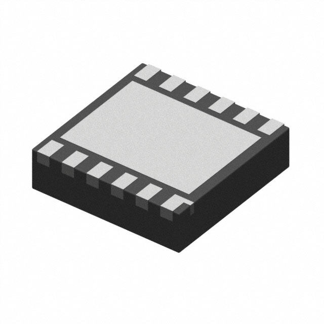
MIC2544-2YM 是 Microchip Technology 生产的一款电源管理 IC,属于配电开关和负载驱动器类别。它主要应用于需要高效、可靠电源管理的场景。

该芯片常用于工业自动化设备、服务器、通信设备以及嵌入式系统中,用于控制和分配电源到不同负载。例如,在工业控制系统中,它可以用于管理多个电机或传感器的电源供应;在服务器和数据中心设备中,可用于优化电源使用效率,实现负载的软启动和限流保护。

MIC2544-2YM 提供双通道高边开关功能,具备过流保护、过温保护和欠压锁定等特性,能够有效保护系统免受电源异常影响。其小型封装(如 10-MSOP)也适合空间受限的设计。

总的来说,该器件适用于需要多路电源控制、负载驱动和电源保护的中高功率电子系统。
| 参数 | 数值 |
| 产品目录 | 集成电路 (IC)半导体 |
| 描述 | IC SW CURR LIMIT HI SIDE 8-SOPUSB开关IC Programmable Current Limit Single High-Side Switch - Lead Free |
| 产品分类 | PMIC - MOSFET,电桥驱动器 - 内部开关集成电路 - IC |
| 品牌 | Micrel |
| 产品手册 | |
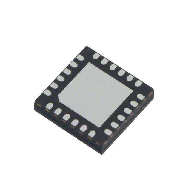
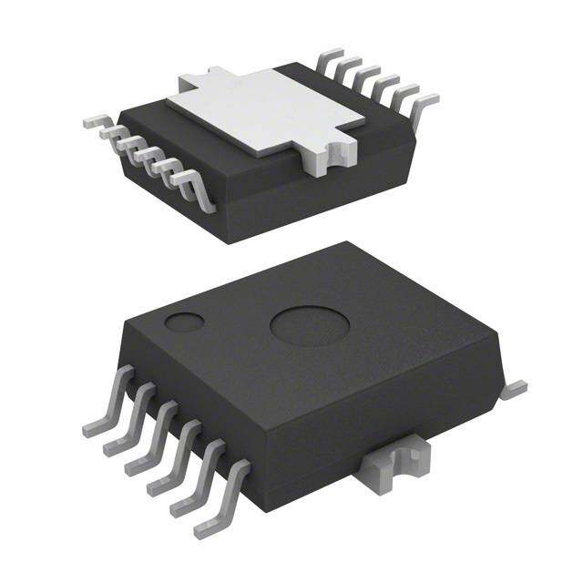
| 产品图片 |
|
| rohs | 符合RoHS无铅 / 符合限制有害物质指令(RoHS)规范要求 |
| 产品系列 | 开关 IC,USB开关IC,Micrel MIC2544-2YM- |
| 数据手册 | |
| 产品型号 | MIC2544-2YM |
| 产品目录页面 | |
| 产品种类 | USB开关IC |
| 供应商器件封装 | 8-SOIC |
| 其它名称 | 576-2168 |
| 包装 | 管件 |
| 商标 | Micrel |
| 安装类型 | 表面贴装 |
| 安装风格 | SMD/SMT |
| 导通电阻 | 80 毫欧 |
| 导通电阻—最大值 | 120 mOhms |
| 封装 | Tube |
| 封装/外壳 | 8-SOIC(0.154",3.90mm 宽) |
| 封装/箱体 | SOIC-8 |
| 工作温度 | -40°C ~ 85°C |
| 工作温度范围 | - 40 C to + 85 C |
| 工厂包装数量 | 95 |
| 开关数量 | Single |
| 开关电流—典型值 | 1.5 A |
| 开关配置 | USB Switch |
| 最大工作温度 | + 85 C |
| 最小工作温度 | - 40 C |
| 标准包装 | 95 |
| 电压-电源 | 2.7 V ~ 5.5 V |
| 电流-峰值输出 | 1.5A |
| 电流-输出/通道 | - |
| 电源电压-最大 | 5.5 V |
| 电源电压-最小 | 2.7 V |
| 电源电流 | 75 uA |
| 空闲时间—最大值 | 22 us |
| 类型 | 高端 |
| 系列 | MIC2544 |
| 输入类型 | 非反相 |
| 输出数 | 1 |
| 运行时间—最大值 | 5 ms |


- 商务部:美国ITC正式对集成电路等产品启动337调查
- 曝三星4nm工艺存在良率问题 高通将骁龙8 Gen1或转产台积电
- 太阳诱电将投资9.5亿元在常州建新厂生产MLCC 预计2023年完工
- 英特尔发布欧洲新工厂建设计划 深化IDM 2.0 战略
- 台积电先进制程称霸业界 有大客户加持明年业绩稳了
- 达到5530亿美元!SIA预计今年全球半导体销售额将创下新高
- 英特尔拟将自动驾驶子公司Mobileye上市 估值或超500亿美元
- 三星加码芯片和SET,合并消费电子和移动部门,撤换高东真等 CEO
- 三星电子宣布重大人事变动 还合并消费电子和移动部门
- 海关总署:前11个月进口集成电路产品价值2.52万亿元 增长14.8%


PDF Datasheet 数据手册内容提取
MIC2544/2548 Programmable Current Limit High-Side Switch General Description Features The MIC2544 and MIC2548 are integrated, high-side • 2.7V to 5.5V input power switches optimized for low loss DC power switching • Adjustable current-limit up to 1.5A and other power management applications, including • Reverse current flow blocking (no “body diode”) Advanced Configuration and Power Interface (ACPI). The MIC2544/48 is a cost-effective, highly integrated • 75μA typical on-state supply current solution that requires few external components to satisfy • 1μA typical off-state supply current USB and ACPI requirements. • 120mΩ maximum on-resistance Load current management features include a precision • Open-drain fault flag resistor-programmable output current-limit and a soft-start • Thermal shutdown circuit which minimizes inrush current when the switch is • Thermal shutdown output latch (MIC2548) enabled. Thermal shutdown, along with current-limit, protects the switch and the attached device. • 2ms (slow) turn-on and fast turnoff The MIC2544/48’s open-drain flag output is used to • Available with active-high or active-low enable indicate current-limiting or thermal shutdown to a local controller. The MIC2548 has an additional internal latch Applications which turns the output off upon thermal shutdown providing robust fault control. The enable signal is • USB power distribution compatible with both 3V and 5V logic, and is also used as • PCI bus power switching the thermal shutdown latch reset for the MIC2548. • Notebook PC The MIC2544 and MIC2548 are available in active-high • ACPI power distribution and active-low enable versions in the 8-pin SOIC • PC card hot swap applications (small-outline integrated circuit) and 8-pin MSOP (micro- small-outline package). • Inrush current-limiting _________________________________________________________________________________________________________ Typical Application Typical Advanced Configuration and Power Interface (ACPI) Application Micrel Inc. • 2180 Fortune Drive • San Jose, CA 95131 • USA • tel +1 (408) 944-0800 • fax + 1 (408) 474-1000 • http://www.micrel.com April 2010 M9999-043010
Micrel, Inc. MIC2544/2548 Ordering Information* Part Number Enable Latch* Temperature Range Package Pb-Free MIC2544-1BM Active High -40°C to +85°C 8-pin SOIC MIC2544-1BMM Active High -40°C to +85°C 8-pin MSOP MIC2544-2BM Active Low -40°C to +85°C 8-pin SOIC MIC2544-2BM Active Low -40°C to +85°C 8-pin MSOP MIC2544-1YM Active High -40°C to +85°C 8-pin SOIC (cid:132) MIC2544-1YMM Active High -40°C to +85°C 8-pin MSOP (cid:132) MIC2544-2YM Active Low -40°C to +85°C 8-pin SOIC (cid:132) MIC2544-2YMM Active Low -40°C to +85°C 8-pin MSOP (cid:132) MIC2548-1BM Active High (cid:132) -40°C to +85°C 8-pin SOIC MIC2548-1BMM Active High (cid:132) -40°C to +85°C 8-pin MSOP MIC2548-2BM Active Low (cid:132) -40°C to +85°C 8-pin SOIC MIC2548-2BMM Active Low (cid:132) -40°C to +85°C 8-pin MSOP MIC2548-1YM Active High (cid:132) -40°C to +85°C 8-pin SOIC (cid:132) MIC2548-1YMM Active High (cid:132) -40°C to +85°C 8-pin MSOP (cid:132) MIC2548-2YM Active Low (cid:132) -40°C to +85°C 8-pin SOIC (cid:132) MIC2548-2YMM Active Low (cid:132) -40°C to +85°C 8-pin MSOP (cid:132) *Thermal Shutdown Latch April 2010 2 M9999-043010
Micrel, Inc. MIC2544/2548 Pin Configuration 8-pin SOIC (M) 8-Pin MSOP (MM) Note: Pins 4 and 5 for SOIC and MSOP are different. Pin Description Pin Number Pin Number MSOP-8 SOIC-9 Pin Name Pin Function Enable (Input): Logic-compatible enable input. Active-high (-1) or active- 1 1 EN low (-2). High input >1.7V typical; low input <1.5V typical. Do not float. MIC2548 only: Also resets thermal shutdown latch. Fault Flag (Output): Active-low, open-drain output. Indicates overcurrent 2 2 FLG or thermal shutdown conditions. MIC2548 only: latched low on thermal shutdown. 3 3 GND Ground. Current Limit: Sets current-limit threshold using an external resistor, R 1 5 4 ILIM SET connected to ground. 154Ω < R < 2.29kΩ. SET 7 7 IN Input: Output MOSFET drain. Also powers internal circuitry. Switch (Output): Output MOSFET source. Pins 6 and 8 must be externally 6,8 6,8 OUT connected. 4 5 NC Not internally connected. April 2010 3 M9999-043010
Micrel, Inc. MIC2544/2548 Absolute Maximum Ratings(1) Operating Ratings(2) Supply Voltage (V )....................................................+7.0V Supply Voltage (V ).....................................+2.7V to +5.5V IN IN Output Voltage (V ).................................................+7.0V Current Limit Set Range...................................0.1A to 1.5A OUT Output Current (I ).................................Internally Limited Ambient Temperature (T )..........................–40°C to +85°C OUT A Enable Input (V )..................................–0.3V to VIN+0.3V Package Thermal Resistance EN Fault Flag Voltage (V ).............................................+7.0V SOIC (θ )........................................................160°C/W FLG JA Fault Flag Current (IFLG)..............................................50mA MSOP (θJA)......................................................206°C/W Storage Temperature (T ).........................–65°C to +150°C s Junction Temperature (T )........................Internally Limited J Lead Temperature (soldering, 5 sec.)........................260°C ESD Rating(3)..................................................................2kV Electrical Characteristics V = +5V; T = 25°C, bold values indicate –40°C to +85°C, unless noted. IN A Symbol Parameter Condition Min Typ Max Units Switch off, OUT = open(4) # 0.75 5 μA Supply Current Switch on, OUT = open(4) 75 160 μA Enable high(4) 2.4 1.7 V V Enable Input Voltage EN Enable low(1) 1.5 0.8 V Enable Input Capacitance Note 5 1 pF R Switch Resistance I = 500mA 80 120 mΩ DS(on) OUT I = 100mA to 1A, V =1V to 4V(6) 184 230 276 V OUT OUT Current Limit Factor I = 500mA to 1.5A, V =1V to 4V(6) 161 230 299 V OUT OUT Output Leakage Current Switch off 1 10 μA t Output Turn-On Delay R = 10Ω, C = 1μF, Figures 1a, 1b 1 2 5 ms ON L L T Output Turn-On Rise Time R = 10Ω, C = 1μF, Figures 1a, 1b 1 2 5 ms R L L T Output Turn-Off Delay R = 10Ω, C = 1μF, Figures 1a, 1b 22 μs OFF L L T Output Turn-Off Fall Time R = 10Ω, C = 1μF, Figures 1a, 1b 21 μs F L L T increasing 140 °C J Overtemperature Threshold Shutdown T decreasing 130 °C J V = 5V, I = 10μA 4 15 Ω IN L Error Flag Output Resistance V = 3.3V, I = 10μA 5 20 Ω IN L Error Flag Off Current V = 5V 0.01 1 μA FLG EN Pulse Reset Width MIC2548 thermal shutdown latch 5 μs V to EN Set-Up MIC2548(6) 0 μs IN Current-Limit Response Time V = 0V(6) 25 μs OUT Overcurrent Flag Response Time V = V /2 to FLG low 5 μs OUT IN Notes: 1. Exceeding the absolute maximum rating may damage the device. 2. The device is not guaranteed to function outside its operating rating. 3. Devices are ESD sensitive. Handling precautions recommended. Human body model, 1.5k in series with 100pF. 4. Off is ≤0.8V and on is ≥2.4V for the MIC2544-1 and MIC2548-1. Off is ≥2.4V and on is ≤0.8V for the MIC2544-2 and MIC2548-2. The enable input has about 200mV of hysteresis. 5. Guaranteed by design but not production tested. 230V 6. Current limit threshold is determined by I = , where R is in ohms. LIMIT R SET SET April 2010 4 M9999-043010
Micrel, Inc. MIC2544/2548 Test Circuit Functional Characteristics Test Circuit Timing Diagrams Figure 1a. MIC2544/48-1 Figure 1b. MIC2544/48-2 April 2010 5 M9999-043010
Micrel, Inc. MIC2544/2548 Timing Diagrams continued Figure 2a. MIC2548-2 Timing: Output is reset by toggling EN Figure 2b. MIC2544-2 Timing April 2010 6 M9999-043010
Micrel, Inc. MIC2544/2548 Typical Characteristics April 2010 7 M9999-043010
Micrel, Inc. MIC2544/2548 Typical Characteristics continued April 2010 8 M9999-043010
Micrel, Inc. MIC2544/2548 Functional Characteristics April 2010 9 M9999-043010
Micrel, Inc. MIC2544/2548 Block Diagram April 2010 10 M9999-043010
Micrel, Inc. MIC2544/2548 Functional Description Adjustable Current-Limit The MIC2544 and MIC2548 are high-side N-channel The short-circuit current-limit is user-adjustable with an switches available with active-high or active-low enable external set resistor. Current-limit in the range of 100mA inputs. Fault conditions turn-off or inhibit turn-on of the to 1.5A is available with a set point accuracy of better output transistor and activate the open-drain error flag than ±20%. The current-limit circuit prevents damage to transistor making it sink current to ground. the output MOSFET and external load. The nominal current-limit value is set with an external Input and Output resistor between ILIM and GND. For a desired current- IN is the power supply connection to the logic circuitry limit, the value of the external set resistor is given by: and the drain of the output MOSFET. OUT is the source of the output MOSFET. In a typical circuit, current flows from IN to OUT toward the load. If VOUT is greater than VIN, current will flow from OUT to IN since the switch is where: bidirectional when enabled. 154Ω < R <2.29kΩ The output MOSFET and driver circuitry are also SET designed to allow the MOSFET source to be externally For example, to set a 1A nominal current-limit, R is SET forced to a higher voltage than the drain (VOUT > VIN) calculated as: when the switch is disabled. In this situation, the MIC2544/48 avoids undesirable current flow from OUT to IN. Both OUT pins must be connected together. Thermal Shutdown Current through R increases with OUT current. SET Thermal shutdown shuts off the output MOSFET and The voltage across R could be monitored with a high SET signals the fault flag if the die temperature exceeds impedance comparator to provide an indication of output 140°C. 10°C of hysteresis prevents the switch from current. R should be between 154Ω ±0.5% and SET turning on until the die temperature drops to 130°C. 2.29kΩ ±0.5%. Overtemperature detection functions only when the Short-Circuit Protection switch is enabled. In the event of a short circuit, the output current will fold The MIC2548 features an internal latch which causes back to approximately 80% of the short-circuit current- the part to remain off after thermal shutdown until a reset limit. pulse is provided via the enable pin (pin 1). While in current-limit, the thermal shutdown latch prevents on/off Fault Flag cycling of the output. FLG is an N-channel, open-drain MOSFET output. Refer to Figures 2a and 2b for timing diagram. The flag The faultflag is active (low) for current-limit or thermal remains low until reset. shutdown conditions. The flag output MOSFET is capable of sinking a 10mA load to typically 100mV Enable Input above ground. EN must be driven logic high or logic low, or be pulled high or low for a clearly defined input. Floating the input may cause unpredictable operation. EN should not be allowed to go negative with respect to GND, and V EN should be less than or equal to V . IN April 2010 11 M9999-043010
Micrel, Inc. MIC2544/2548 Application Information where: T = junction temperature j Supply Filtering T = ambient temperature A A 0.1μF to 1μF bypass capacitor from IN to GND, θ = is the thermal resistance of the package JA located near the MIC2544 and MIC2548, is strongly recommended to control supply transients. Without a Transient Overcurrent Filter bypass capacitor, an output short may cause sufficient The inrush current from the connection of a heavy ringing on the input (from supply lead inductance) to capacitive load may cause the fault flag to fall for 10μs to damage internal control circuitry. 200μs while the switch is in a constant-current mode, Input transients must not exceed the absolute maximum charging the capacitance. supply voltage (V = 6V) even for a short duration. IN max Adding an optional series resistor-capacitor (R ) in SET2 parallel with R , as shown in Figure 4, allows the SET transient current-limit to be set to a different value than steady state. A typical USB hot-plug inrush is 2A to 3A for 10μs to 20μs. If R is 435Ω (510mA), an R of SET SET2 88Ω (2.5A) and C of 1μF (RC = 100μs) allows SET transient surge of 3A to pass for 100μs without tripping the overcurrent flag (FLG). USB Power Distribution The MIC2544 is ideal for meeting USB power distribution requirements. Figure 4 depicts a USB Host application. RSET should be set to a value providing a current-limit Figure 3. Supply Bypassing >500mA. Power Dissipation The accurate current-limit of the MIC2544 will reduce The device's junction temperature depends on several power supply current requirements. Also, fast reaction to factors such as the load, PCB layout, ambient short circuit faults prevent voltage droop in mobile temperature, and package type. Equations that can be PC applications. used to calculate power dissipation and junction Printed Circuit Board Hot-Plug temperature are found below. The MIC2544/48 are ideal inrush current-limiters suitable Calculation of power dissipation can be accomplished by for hot-plug applications. Due to the integrated charge the following equation: pump, the MIC2544/48 presents a high impedance when PD = R × (I )2 DS(on) OUT off and slowly becomes a low impedance as it turns on. To relate this to junction temperature, the following This “softstart” feature effectively isolates power supplies equation can be used: from highly capacitive loads by reducing inrush current T = P × θ + T during hot-plug events. Figure 5 shows how the j D JA A MIC2544 may be used in a hot-plug application. Figure 4. USB Host Application Note: MSOP package option uses pin 5 for ILIM. Pin 4 is not connected (NC). Bold lines indicate 0.1” wide, 1-oz. copper high-current traces. April 2010 12 M9999-043010
Micrel, Inc. MIC2544/2548 Figure 5. Hot Plug Application April 2010 13 M9999-043010
Micrel, Inc. MIC2544/2548 Package Information 8-pin SOIC (M) 8-Pin MSOP (MM) MICREL, INC. 2180 FORTUNE DRIVE SAN JOSE, CA 95131 USA TEL +1 (408) 944-0800 FAX +1 (408) 474-1000 WEB http://www.micrel.com The information furnished by Micrel in this data sheet is believed to be accurate and reliable. However, no responsibility is assumed by Micrel for its use. Micrel reserves the right to change circuitry and specifications at any time without notification to the customer. Micrel Products are not designed or authorized for use as components in life support appliances, devices or systems where malfunction of a product can reasonably be expected to result in personal injury. Life support devices or systems are devices or systems that (a) are intended for surgical implant into the body or (b) support or sustain life, and whose failure to perform can be reasonably expected to result in a significant injury to the user. A Purchaser’s use or sale of Micrel Products for use in life support appliances, devices or systems is a Purchaser’s own risk and Purchaser agrees to fully indemnify Micrel for any damages resulting from such use or sale. © 2004 Micrel, Incorporated. April 2010 14 M9999-043010
Mouser Electronics Authorized Distributor Click to View Pricing, Inventory, Delivery & Lifecycle Information: M icrel: MIC2544-1YMM TR MIC2544-2YMM TR MIC2548-2YM TR MIC2548-2YMM TR MIC2544-2YM TR MIC2548-1YM TR MIC2548-1YMM TR M icrochip: MIC2544-2YM MIC2544-1YMM MIC2548-2YMM MIC2548-1YM MIC2544-2YMM MIC2548-1YMM MIC2544-1YM MIC2548-2YM MIC2544-1YMM-TR MIC2548-1YMM-TR MIC2544-2YM-TR MIC2544-1YM-TR MIC2548-2YM-TR MIC2548-1YM-TR MIC2544-2YMM-TR MIC2548-2YMM-TR