ICGOO在线商城 > 分立半导体产品 > 晶闸管 - SCR - 模块 > MCD95-08IO8B
 Datasheet下载
- 型号: MCD95-08IO8B
- 制造商: IXYS
- 库位|库存: xxxx|xxxx
- 要求:
| 数量阶梯 | 香港交货 | 国内含税 |
| +xxxx | $xxxx | ¥xxxx |
查看当月历史价格
查看今年历史价格
MCD95-08IO8B产品简介:
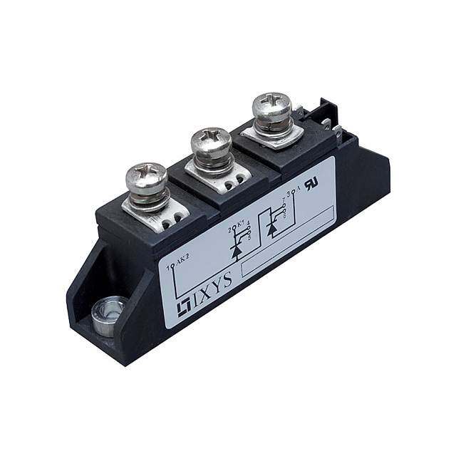
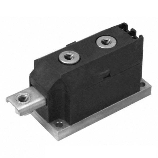
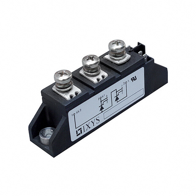
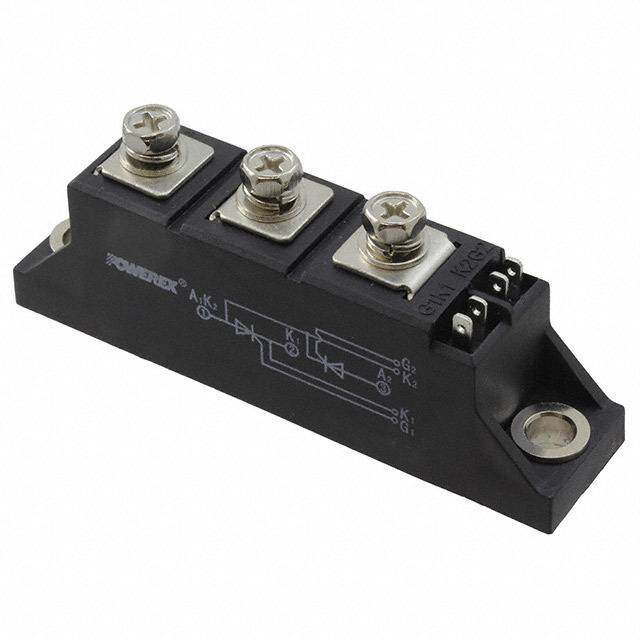
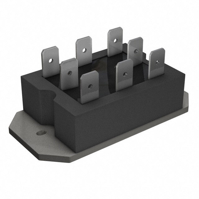
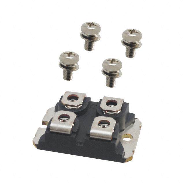
ICGOO电子元器件商城为您提供MCD95-08IO8B由IXYS设计生产,在icgoo商城现货销售,并且可以通过原厂、代理商等渠道进行代购。 MCD95-08IO8B价格参考¥182.91-¥234.84。IXYSMCD95-08IO8B封装/规格:晶闸管 - SCR - 模块, SCR Module 800V 180A Series Connection - SCR/Diode Chassis Mount TO-240AA。您可以下载MCD95-08IO8B参考资料、Datasheet数据手册功能说明书,资料中有MCD95-08IO8B 详细功能的应用电路图电压和使用方法及教程。
IXYS品牌的MCD95-08IO8B是一种晶闸管(SCR,Silicon Controlled Rectifier)模块,广泛应用于工业和电力电子领域。以下是其主要应用场景:

 1. 电机控制
   - MCD95-08IO8B可用于交流电机的启动、调速和制动控制。通过调节SCR的触发角,可以改变电机输入电压,从而实现对转速的精确控制。
   - 应用于工业设备中的风机、水泵、压缩机等场合。

 2. 电源管理
   - 在直流电源系统中,该模块可作为整流器或斩波器使用,用于将交流电转换为可控的直流电。
   - 常见于不间断电源(UPS)、电池充电器以及焊接电源中。

 3. 加热控制
   - SCR模块适用于工业加热系统,如电阻炉、热处理设备和感应加热装置。通过相位控制技术,可以实现对加热功率的精准调节。
   - 提供稳定的温度控制能力,满足不同材料加工需求。

 4. 照明调光
   - 在大功率照明系统中,MCD95-08IO8B可用于调光控制,例如舞台灯光、工厂高顶灯等场景。
   - 实现亮度调节的同时,降低能耗并延长灯具寿命。

 5. 逆变焊机
   - 该模块在焊接设备中发挥关键作用,用于控制焊接电流和电压输出,确保焊接质量稳定。
   - 支持多种焊接工艺,包括手工电弧焊、气体保护焊等。

 6. 软启动器
   - MCD95-08IO8B可用于电动机软启动器中,减少启动时的冲击电流,保护电机及相关设备。
   - 特别适合大型电机的平稳启动。

 总结
MCD95-08IO8B凭借其高可靠性、高效能和耐高压特性,在需要精确功率控制的场景中表现出色。它能够适应恶劣的工作环境,并提供稳定的性能表现,是工业自动化、电力电子及能源管理领域的理想选择。
| 参数 | 数值 |
| 产品目录 | |
| 描述 | THYRISTOR DOUB 800V 116A TO-240分立半导体模块 95 Amps 800V |
| 产品分类 | SCR - 模块分离式半导体 |
| GateTriggerCurrent-Igt | 150 mA |
| 品牌 | IXYS |
| 产品手册 | |
| 产品图片 |
|
| rohs | 符合RoHS无铅 / 符合限制有害物质指令(RoHS)规范要求 |
| 产品系列 | 分立半导体模块,IXYS MCD95-08io8B- |
| 数据手册 | |
| 产品型号 | MCD95-08IO8B |
| SCR数,二极管 | 1 SCR,1 个二极管 |
| 产品 | Power Semiconductor Modules |
| 产品种类 | 分立半导体模块 |
| 保持电流Ih最大值 | 200 mA |
| 其它名称 | MCD95-08I08B |
| 其它有关文件 | |
| 包装 | 散装 |
| 反向电压 | 800 V |
| 商标 | IXYS |
| 安装类型 | 底座安装 |
| 安装风格 | Screw |
| 封装 | Bulk |
| 封装/外壳 | TO-240AA |
| 封装/箱体 | TO-240-AA |
| 工厂包装数量 | 6 |
| 栅极触发电流-Igt | 150 mA |
| 标准包装 | 6 |
| 正向电压下降 | 1.5 V |
| 电压-断态 | 800V |
| 电流-不重复浪涌50、60Hz(Itsm) | 2250A,2400A |
| 电流-保持(Ih)(最大值) | 200mA |
| 电流-栅极触发(Igt)(最大值) | 150mA |
| 电流-通态(It(AV))(最大值) | 116A |
| 电流-通态(It(RMS))(最大值) | 180A |
| 类型 | Thyristor / Diode Modules |
| 系列 | MCD95 |
| 结构 | 串联 - SCR/二极管 |


- 商务部:美国ITC正式对集成电路等产品启动337调查
- 曝三星4nm工艺存在良率问题 高通将骁龙8 Gen1或转产台积电
- 太阳诱电将投资9.5亿元在常州建新厂生产MLCC 预计2023年完工
- 英特尔发布欧洲新工厂建设计划 深化IDM 2.0 战略
- 台积电先进制程称霸业界 有大客户加持明年业绩稳了
- 达到5530亿美元!SIA预计今年全球半导体销售额将创下新高
- 英特尔拟将自动驾驶子公司Mobileye上市 估值或超500亿美元
- 三星加码芯片和SET,合并消费电子和移动部门,撤换高东真等 CEO
- 三星电子宣布重大人事变动 还合并消费电子和移动部门
- 海关总署:前11个月进口集成电路产品价值2.52万亿元 增长14.8%

PDF Datasheet 数据手册内容提取
MCC 95 MCD 95 Thyristor Modules I = 2x 180 A TRMS I = 2x 116 A Thyristor/Diode Modules TAVM V = 800-1800 V RRM 3 6 V V Type 2 7 RSM RRM 4 V V 1 5 DSM DRM V V Version 1B 8B Version 1B 8B 900 800 MCC 95-08 io1B / io8B MCD 95-08 io1B / io8B 1300 1200 MCC 95-12 io1B / io8B MCD 95-12 io1B / io8B 1500 1400 MCC 95-14 io1B / io8B MCD 95-14 io1B / io8B 1700 1600 MCC 95-16 io1B / io8B MCD 95-16 io1B / io8B 1900 1800 MCC 95-18 io1B / io8B MCD 95-18 io1B / io8B 3 6 7 1 5 4 2 Symbol Conditions Maximum Ratings I , I T = T 180 A MCC Version 1 TRMS FRMS VJ VJM I , I T = 85°C; 180° sine 116 A TAVM FAVM C I , I T = 45°C t = 10 ms (50 Hz) 2250 A TSM FSM VJ 3 1 5 4 2 V = 0 t = 8.3 ms (60 Hz) 2400 A R TVJ = TVJM t = 10 ms (50 Hz) 2000 A MCD Version 1 V = 0 t = 8.3 ms (60 Hz) 2150 A R I2t T = 45°C t = 10 ms (50 Hz) 25 300 A2s VJ 3 6 1 5 2 V = 0 t = 8.3 ms (60 Hz) 23 900 A2s R TVJ = TVJM t = 10 ms (50 Hz) 20 000 A2s MCC Version 8 V = 0 t = 8.3 ms (60 Hz) 19 100 A2s R (di/dt) T = T repetitive, I = 250 A 150 A/µs cr VJ VJM T f = 50 Hz; t = 200 µs; 3 1 5 2 p V = 2/ V D 3 DRM MCD Version 8 I = 0.45 A non repetitive, I = I 500 A/µs G T TAVM di /dt = 0.45 A/µs G (dv/dt) T = T ; V = 2/ V 1000 V/µs Features cr VJ VJM D 3 DRM R = ∞; method 1 (linear voltage rise) GK • International standard package, P T = T ; t = 30 µs 10 W JEDEC TO-240 AA GM VJ VJM p I = I ; t = 500 µs 5 W • Direct copper bonded AlO -ceramic T T(AV)M p 2 3 P 0.5 W base plate GAV • Planar passivated chips V 10 V RGM • Isolation voltage 3600 V~ T -40...+125 °C • UL registered, E 72873 VJ T 125 °C • Gate-cathode twin pins for version 1 VJM T -40...+125 °C stg V 50/60 Hz, RMS t = 1 min 3000 V~ Applications ISOL IISOL < 1 mA t = 1 s 3600 V~ • DC Motor control M Mounting torque (M5) 2.5 - 4 Nm • Softstart AC motor controller d Terminal connection torque (M5) 2.5 - 4 Nm • Light, heat and temperature control Weight Typical including screws 85 g Advantages Data according to IEC 60747 and refer to a single diode unless otherwise stated. • Space and weight savings • Simple mounting with two screws • Improved temperature & power cycling • Reduced protection circuits IXYS reserves the right to change limits, test conditions and dimensions. 20101116a © 2010 IXYS All rights reserved 1 - 5
MCC 95 MCD 95 100 Symbol Conditions Characteristic Values typ. max. tp= 30µs t =500µs p I , I V / V = V / V T = T 5 mA RRM DRM R D RRM DRM VJ VJM P =120W GM V, V I / I = 300 A T = 25°C 1.5 V 60W T F T F VJ 10 P = 8W GAV V For power-loss calculations only 0.8 V T0 V r T = T 2.4 mW G t VJ VJM V V = 6 V T = 25°C 2.5 V [V] GT D VJ T = -40°C 2.6 V VJ 1 I V = 6 V T = 25°C 150 mA GT D VJ T = -40°C 200 mA C C IGT(TVJ=-40°C) VJ 25° 25° IGT(TVJ= 0°C) VGD VD = 2/3 VDRM; TVJ = TVJM 0.2 V 1 IGT(TVJ=25°C) IGD 10 mA 0.1 IGD I t = 10 µs; V = 6 V T = 25°C 450 mA 0.01 0.1 1 10 L p D VJ IG = 0.45 A; diG /dt = 0.45 A/µs IG [A] I V = 6 V; R = ∞; T = 25°C 200 mA Fig. 1 Gate trigger characteristics H D GK VJ t V = ½V T = 25°C 2 µs gd D DRM VJ IG = 0.45 A; diG /dt = 0.45 A/µs 100 T =25°C t V = 2/ V T = T 185 µs VJ q D 3 DRM VJ VJM dv/dt = 20 V/µs; -di/dt = 10 A/µs I = 150 A; V = 100 V; t = 200 µs T R p Q I / I = 50 A; -di/dt = 6 A/µs T = T 170 µC 10 S T F VJ VJM I 45 A RM t gd RthJC per thyristor; DC current 0.22 K/W per module other values 0.11 K/W [µs] limit R per thyristor; DC current see Fig. 8/9 0.42 K/W thJK 1 per module 0.21 K/W typ. d Creeping distance on surface 12.7 mm S d Creepage distance in air 9.6 mm A a Maximum allowable acceleration 50 m/s2 0.1 0.01 0.1 1 10 Optional accessories for modules I [A] G Coded gate/cathode twin plugs with wire length = 350 mm, gate = yellow, cathode = red Fig. 2 Gate trigger delay time Type ZY 200L (L = Left for pin pair 4/5) UL 758, style 1385, Type ZY 200R (R = Right for pin pair 6/7) CSA class 5851, guide 460-1-1 IXYS reserves the right to change limits, test conditions and dimensions. 20101116a © 2010 IXYS All rights reserved 2 - 5
MCC 95 MCD 95 Dimensions in mm (1 mm = 0.0394“) MCC... Version 1B MCD... Version 1B A 2.8 - 0.8 A 2.8 - 0.8 DIN 46244 DIN 46244 5 5 3. 3. +0.830.2 - 02 28.5 +0.47.5 - 01 23.5 29.7 ±0.2 +0.830.2 - 02 28.5 +0.47.5 - 01 23.5 29.7 ±0.2 5 65 x 19 5 65 x 19 2 2 0. 0. General tolerance: DIN ISO 2768 class „c“ General tolerance: DIN ISO 2768 class „c“ 92 ±0.5 92 ±0.5 80 ±0.3 6 80 ±0.3 6 5 ±0.1 M5 10 4.4 5 ±0.1 M5 10 5 5. 5 5. 0.8 ±0.2 14.8 10 ±0.1 5 0.8 ±0.2 14.8 10 ±0.1 2 2 4 4 25 ±0.3 4. 25 ±0.3 4. 45 ±0.3 45 ±0.3 65 ±0.3 65 ±0.3 Optional accessories: Keyed gate/cathode twin plugs Optional accessories: Keyed gate/cathode twin plugs Wire length: 350 mm, gate = yellow, cathode = red Wire length: 350 mm, gate = yellow, cathode = red UL 758, style 1385, CSA class 5851, guide 460-1-1 UL 758, style 1385, CSA class 5851, guide 460-1-1 Type ZY 200L (L = Left for pin pair 4/5) Type ZY 200L (L = Left for pin pair 4/5) Type ZY 200R (R = Right for pin pair 6/7) MCC... Version 8B MCD... Version 8B A 2.8 - 0.8 A 2.8 - 0.8 DIN 46244 DIN 46244 5 5 3. 3. +0.830.2 - 02 28.5 +0.47.5 - 01 23.5 29.7 ±0.2 +0.830.2 - 02 28.5 +0.47.5 - 01 23.5 29.7 ±0.2 5 65 x 19 5 65 x 19 2 2 0. 0. General tolerance: DIN ISO 2768 class „c“ General tolerance: DIN ISO 2768 class „c“ 92 ±0.5 92 ±0.5 80 ±0.3 6 80 ±0.3 6 0.1 M5 10 0.1 M5 10 ± ± 5 5 0.8 ±0.25 14.8 10 ±0.1 5. 6.9 6.9 0.8 ±0.25 14.8 10 ±0.1 5. 6.9 2 2 25 ±0.3 25 ±0.3 45 ±0.3 45 ±0.3 65 ±0.3 65 ±0.3 IXYS reserves the right to change limits, test conditions and dimensions. 20101116a © 2010 IXYS All rights reserved 3 - 5
MCC 95 MCD 95 3000 105 250 V = 0 V R 2500 200 DC 50 Hz 180° sin 80% V I 120° 2000 RRM TAVM 60° T = 45°C VJ 150 30° I TSM TVJ = 125°C I2t [A] 1500 [A] [A2s] 100 1000 TVJ = 45°C 50 500 T = 125°C VJ 0 104 0 0.001 0.01 0.1 1 1 10 0 25 50 75 100 125 150 t [ms] t [s] T [°C] C Fig. 3 Surge overload current I , Fig. 4 I2t versus time (1-10 ms) Fig. 4a Maximum forward current TSM I : Crest value, t: duration at case temperature FSM 250 R K/W thKA 0.4 200 0.6 0.8 1 P 1.2 tot 150 1.5 2 [W] 3 DC 100 180° sin 120° 60° 30° Fig. 5 Power dissipation versus 50 on-state current & ambient temperature (per thyristor or diode) 0 0 50 100 150 0 50 100 150 I , I [A] T [°C] TAVM FAVM a 1000 R K/W thKA 800 0.03 0.06 0.08 P tot 0.12 600 0.15 [W] 0.3 0.5 400 Circuit B6 3x MCC95 or Fig. 6 Three phase rectifier bridge: 200 3x MCD95 Power dissipation vs. direct output current and ambient temperature 0 0 100 200 300 0 50 100 150 I [A] T [°C] dAVM a IXYS reserves the right to change limits, test conditions and dimensions. 20101116a © 2010 IXYS All rights reserved 4 - 5
MCC 95 MCD 95 1200 Fig. 7 Three phase AC-controller: Circuit Power dissipation versus RMS W3 1000 3x MCC95 or RthKA K/W output current and ambient 3x MCD95 0.03 temperature 0.06 800 0.08 P 0.12 tot 0.15 600 0.3 [W] 0.5 400 200 0 0 50 100 150 200 250 0 50 100 150 I [A] T [°C] RMS a 0.30 Fig. 8 Transient thermal impedance junction to case 0.25 (per thyristor or diode) R for various conduction angles d: thJC 0.20 30° d R (K/W) 60° thJC ZthJC 120° DC 0.22 0.15 180° 180° 0.23 [K/W] DC 120° 0.25 0.10 60° 0.27 30° 0.28 Constants for Z calculation: 0.05 thJC i R (K/W) t (s) thi i 1 0.0066 0.0019 0.00 10-3 10-2 10-1 100 101 102 2 0.0678 0.0477 t [s] 3 0.1456 0.344 0.5 Fig. 9 Transient thermal impedance junction to heatsink (per thyristor or diode) 0.4 30° R for various conduction angles d: 60° thJK 120° d R (K/W) thJK ZthJK 0.3 D18C0° DC 0.42 180° 0.43 [K/W] 120° 0.45 0.2 60° 0.47 30° 0.48 0.1 Constants for Z calculation: thJK i R (K/W) t (s) thi i 1 0.0066 0.0019 0.0 10-3 10-2 10-1 100 101 102 103 2 0.0678 0.0477 t [s] 3 0.1456 0.344 4 0.2 1.32 IXYS reserves the right to change limits, test conditions and dimensions. 20101116a © 2010 IXYS All rights reserved 5 - 5
Mouser Electronics Authorized Distributor Click to View Pricing, Inventory, Delivery & Lifecycle Information: I XYS: MCD95-08io1B MCD95-08io8B MCD95-12io1B MCD95-12io8B MCD95-14io1B MCD95-14io8B MCD95-16io1B MCD95-16io8B MCD95-18io1B MCD95-18io8B MCC95-08io1B MCC95-08io8B MCC95-12io1B MCC95-12io8B MCC95-14io1B MCC95-14io8B MCC95-16io1B MCC95-16io8B MCC95-18io1B MCC95-18io8B