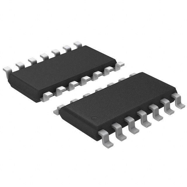
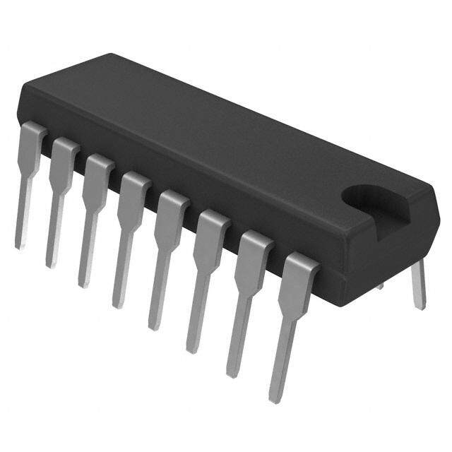
ICGOO在线商城 > 集成电路(IC) > 线性 - 放大器 - 仪表,运算放大器,缓冲器放大器 > MAX4200ESA
- 型号: MAX4200ESA
- 制造商: Maxim
- 库位|库存: xxxx|xxxx
- 要求:
| 数量阶梯 | 香港交货 | 国内含税 |
| +xxxx | $xxxx | ¥xxxx |
查看当月历史价格
查看今年历史价格
MAX4200ESA产品简介:
ICGOO电子元器件商城为您提供MAX4200ESA由Maxim设计生产,在icgoo商城现货销售,并且可以通过原厂、代理商等渠道进行代购。 MAX4200ESA价格参考。MaximMAX4200ESA封装/规格:线性 - 放大器 - 仪表,运算放大器,缓冲器放大器, 缓冲器 放大器 1 电路 8-SOIC。您可以下载MAX4200ESA参考资料、Datasheet数据手册功能说明书,资料中有MAX4200ESA 详细功能的应用电路图电压和使用方法及教程。
MAX4200ESA 是由 Maxim Integrated(现为 Analog Devices 旗下公司)生产的一款高精度、低功耗的运算放大器,属于线性放大器类别。它具备轨对轨输入输出特性,适用于多种模拟信号处理场景。

该器件常用于以下应用场景:

1. 工业自动化与控制系统:如传感器信号调理、过程控制中的模拟信号放大和滤波处理,因其高精度和低温漂特性,适合用于压力、温度、流量等传感器信号的放大。

2. 便携式仪器仪表:由于其低功耗设计,MAX4200ESA 被广泛应用于电池供电的便携式测试设备、数据采集系统和手持式测量工具中。

3. 医疗电子设备:例如心电图机(ECG)、血氧仪等需要高稳定性和低噪声性能的生物信号采集系统中,用作前置放大器或缓冲器。

4. 通信设备:在通信系统中用于信号链路中的模拟信号放大、滤波和驱动,尤其适用于要求低失真和高稳定性的场合。

5. 汽车电子:可用于车载传感器接口电路、车内娱乐系统的音频信号处理模块等。

6. 消费类电子产品:如高保真音频设备、智能家电中的模拟信号处理部分。

综上所述,MAX4200ESA 凭借其优良的电气性能和宽泛的工作电压范围,在需要高精度、低噪声和低功耗的多种应用中均有广泛应用。
| 参数 | 数值 |
| -3db带宽 | 660MHz |
| 产品目录 | 集成电路 (IC)半导体 |
| 描述 | IC OPAMP BUFFER 660MHZ 8SOIC高速运算放大器 Ultra-High-Speed Open-Loop Buffer |
| 产品分类 | Linear - Amplifiers - Instrumentation, OP Amps, Buffer Amps集成电路 - IC |
| 品牌 | Maxim Integrated |
| 产品手册 | |
| 产品图片 |
|
| rohs | 否含铅 / 不符合限制有害物质指令(RoHS)规范要求 |
| 产品系列 | 放大器 IC,高速运算放大器,Maxim Integrated MAX4200ESA- |
| 数据手册 | |
| 产品型号 | MAX4200ESA |
| 产品 | Current Feedback Amplifier |
| 产品培训模块 | http://www.digikey.cn/PTM/IndividualPTM.page?site=cn&lang=zhs&ptm=25703http://www.digikey.cn/PTM/IndividualPTM.page?site=cn&lang=zhs&ptm=25705 |
| 产品种类 | |
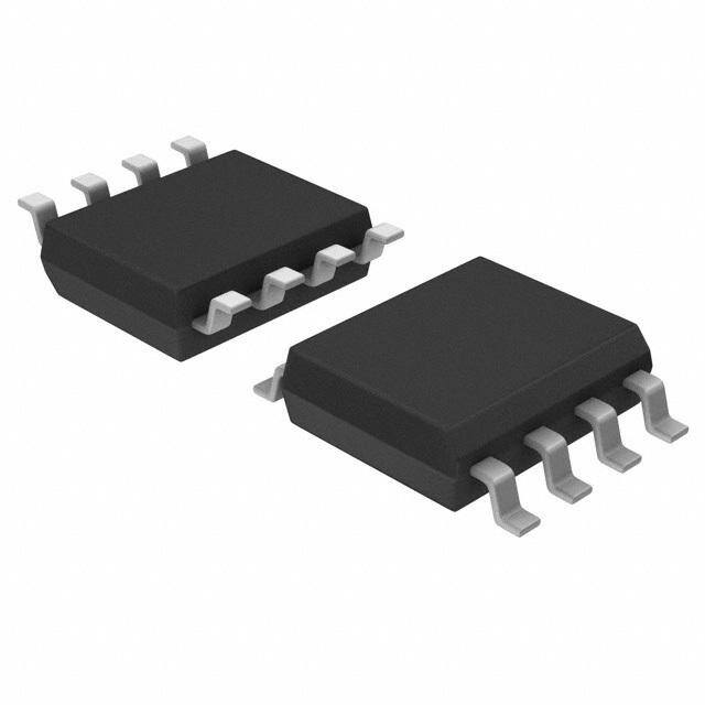
| 供应商器件封装 | 8-SOIC N |
| 包装 | 管件 |
| 压摆率 | 4200 V/µs |
| 商标 | Maxim Integrated |
| 增益带宽积 | - |
| 安装类型 | 表面贴装 |
| 安装风格 | SMD/SMT |
| 封装 | Tube |
| 封装/外壳 | 8-SOIC(0.154",3.90mm 宽) |
| 封装/箱体 | SO-8 |
| 工作温度 | -40°C ~ 85°C |
| 工作电源电压 | +/- 4 V to +/- 5.5 V |
| 工厂包装数量 | 100 |
| 带宽 | 660 MHz |
| 拓扑结构 | Current Feedback |
| 放大器类型 | 缓冲器 |
| 最大功率耗散 | 471 mW |
| 最大工作温度 | + 85 C |
| 最小工作温度 | - 40 C |
| 标准包装 | 1 |
| 电压-电源,单/双 (±) | ±4 V ~ 5.5 V |
| 电压-输入失调 | 1mV |
| 电压增益dB | 0.35 dB |
| 电流-电源 | 2.2mA |
| 电流-输入偏置 | 800nA |
| 电流-输出/通道 | 90mA |
| 电源电流 | 2.2 mA |
| 电路数 | 1 |
| 系列 | MAX4200 |
| 转换速度 | 4200 V/us |
| 输入补偿电压 | 15 mV |
| 输出电流 | 90 mA |
| 输出类型 | - |
| 通道数量 | 1 Channel |
| 零件号别名 | MAX4200 |




- 商务部:美国ITC正式对集成电路等产品启动337调查
- 曝三星4nm工艺存在良率问题 高通将骁龙8 Gen1或转产台积电
- 太阳诱电将投资9.5亿元在常州建新厂生产MLCC 预计2023年完工
- 英特尔发布欧洲新工厂建设计划 深化IDM 2.0 战略
- 台积电先进制程称霸业界 有大客户加持明年业绩稳了
- 达到5530亿美元!SIA预计今年全球半导体销售额将创下新高
- 英特尔拟将自动驾驶子公司Mobileye上市 估值或超500亿美元
- 三星加码芯片和SET,合并消费电子和移动部门,撤换高东真等 CEO
- 三星电子宣布重大人事变动 还合并消费电子和移动部门
- 海关总署:前11个月进口集成电路产品价值2.52万亿元 增长14.8%




PDF Datasheet 数据手册内容提取
Click here for production status of specific part numbers. MAX4200–MAX4205 Ultra-High-Speed, Low-Noise, Low-Power, SOT23 Open-Loop Buffers General Description Features The MAX4200–MAX4205 are ultra-high-speed, open- ● 2.2mA Supply Current loop buffers featuring high slew rate, high output current, ● High Speed low noise, and excellent capacitive-load-driving capability. • 780MHz -3dB Bandwidth (MAX4201/MAX4202) The MAX4200/MAX4201/MAX4202 are single buffers, • 280MHz 0.1dB Gain Flatness (MAX4201/MAX4202) while the MAX4203/MAX4204/MAX4205 are dual buffers. • 4200V/μs Slew Rate The MAX4201/MAX4204 have integrated 50Ω termination ● Low 2.1nV/√Hz Voltage-Noise Density resistors, making them ideal for driving 50Ω transmission lines. The MAX4202/MAX4205 include 75Ω back- ● Low 0.8pA/√Hz Current-Noise Density termination resistors for driving 75Ω transmission lines. ● High ±90mA Output Drive (MAX4200/MAX4203) The MAX4200/MAX4203 have no internal termination ● Excellent Capacitive-Load-Driving Capability resistors. ● Available in Space-Saving SOT23 or μMAX® The MAX4200–MAX4205 use a proprietary architecture Packages to achieve up to 780MHz -3dB bandwidth, 280MHz 0.1dB gain flatness, 4200V/μs slew rate, and ±90mA output current Applications drive capability. They operate from ±5V supplies and draw ● High-Speed DAC Buffers only 2.2mA of quiescent current. These features, along ● Wireless LANs with low-noise performance, make these buffers suitable ● Digital-Transmission Line Drivers for driving high-speed analog-to-digital converter (ADC) ● High-Speed ADC Input Buffers inputs or for data-communications applications. ● IF/Communications Systems Typical Application Circuit RT* 50Ω CABLE 50Ω IN OUT REXT* MAX4201 50Ω COAXIAL CABLE DRIVER *RL = RT + REXT μMAX is a registered trademark of Maxim Integrated Products, Inc. 19-1338; Rev 4; 12/17
MAX4200–MAX4205 Ultra-High-Speed, Low-Noise, Low-Power, SOT23 Open-Loop Buffers Absolute Maximum Ratings Supply Voltage (VCC to VEE) ..............................................+12V Operating Temperature Range ...........................-40°C to +85°C Voltage on Any Pin to GND ...........(VEE - 0.3V) to (VCC + 0.3V) Storage Temperature Range ............................-65°C to +150°C Output Short-Circuit Duration to GND .......................Continuous Lead Temperature (soldering, 10s) .................................+300°C Continuous Power Dissipation (TA = +70°C) Soldering Temperature (reflow) ........................................+260°C 5-Pin SOT23 (derate 7.1mW/°C above +70°C) ..........571mW Junction Temperature ......................................................+150°C 8-Pin μMAX (derate 4.1mW/°C above +70°C) ............330mW 8-Pin SO (derate 5.9mW/°C above +70°C) .................471mW Stresses beyond those listed under “Absolute Maximum Ratings” may cause permanent damage to the device. These are stress ratings only, and functional operation of the device at these or any other conditions beyond those indicated in the operational sections of the specifications is not implied. Exposure to absolute maximum rating conditions for extended periods may affect device reliability. DC Electrical Characteristics (VCC = +5V, VEE = -5V, RL = ∞, TA = TMIN to TMAX, unless otherwise noted. Typical values are at TA = +25°C.) PARAMETER SYMBOL CONDITIONS MIN TYP MAX UNITS Operating Supply Voltage VS Guaranteed by PSR test ±4 ±5.5 V Quiescent Supply Current IS Per buffer, VIN = 0V 2.2 4 mA Input Offset Voltage VOS VIN = 0V 1 15 mV Input Offset Voltage Drift TCVOS VIN = 0V 20 μV/°C Input Offset Voltage MAX4203/MAX4204/MAX4205 0.4 mV Matching Input Bias Current IB 0.8 10 μA Input Resistance RIN (Note 1) 500 kΩ -3.0V ≤ MAX4200/MAX4203, REXT = 150Ω 0.9 0.96 1.1 Voltage Gain AV VOUT ≤ MAX4201/MAX4204, REXT = 50Ω 0.42 0.50 0.58 V/V 3.0V MAX4202/MAX4205, REXT = 75Ω 0.41 0.50 0.59 Power-Supply Rejection PSR VS = ±4V to ±5.5V 55 72 dB MAX4200/MAX4203 8 Output Resistance ROUT f = DC MAX4201/MAX4204 50 Ω MAX4202/MAX4205 75 MAX4200/MAX4203 ±90 Output Current IOUT RL = 30Ω MAX4201/MAX4204 ±52 mA MAX4202/MAX4205 ±44 MAX4200/MAX4203 150 Short-Circuit Output Current ISC Sinking or sourcing MAX4201/MAX4204 90 mA MAX4202/MAX4205 75 RL = 150Ω ±3.3 ±3.8 MAX4200/MAX4203 RL = 100Ω ±3.2 ±3.7 Output-Voltage Swing VOUT RL = 37.5Ω ±3.3 V MAX4201/MAX4204 RL = 50Ω ±1.9 ±2.1 MAX4202/MAX4205 RL = 75Ω ±2.0 ±2.3 www.maximintegrated.com Maxim Integrated │ 2
MAX4200–MAX4205 Ultra-High-Speed, Low-Noise, Low-Power, SOT23 Open-Loop Buffers AC Electrical Characteristics (continued) (VCC = +5V, VEE = -5V, RL = 100Ω for MAX4200/MAX4201/MAX4203/MAX4204, RL = 150Ω for MAX4202/MAX4205, TA = TMIN to TMAX, unless otherwise noted. Typical values are at TA = +25°C.) PARAMETER SYMBOL CONDITIONS MIN TYP MAX UNITS MAX4200 660 MAX4201/MAX4202 780 -3dB Bandwidth BW(-3dB) VOUT ≤ 100mVRMS MHz MAX4203 530 MAX4204/MAX4205 720 MAX4200 220 MAX4201/MAX4202 280 0.1dB Bandwidth BW(0.1dB) VOUT ≤ 100mVRMS MHz MAX4203 130 MAX4204/MAX4205 230 MAX4200/MAX4201/MAX4202 490 Full-Power Bandwidth FPBW VOUT ≤ 2VP-P MHz MAX4203/MAX4204/MAX4205 310 Slew Rate SR VOUT = 2V step 4200 V/μs Group Delay Time 405 ps Settling Time to 0.1% tS VOUT = 2V step 12 ns f = 5MHz -48 MAX4200/MAX4201/ f = 20MHz -45 MAX4202 Spurious-Free Dynamic SFDR VOUT = f = 100MHz -34 dBc Range 2VP-P f = 5MHz -47 MAX4203/MAX4204/ f = 20MHz -44 MAX4205 f = 100MHz -32 Second harmonic -72 MAX4200/MAX4201/ MAX4202, f = 500kHz, Third harmonic -48 VOUT = 2VP-P Total harmonic -48 Harmonic Distortion HD dBc Second harmonic -83 MAX4203/MAX4204/ MAX4205, f = 500kHz, Third harmonic -47 VOUT = 2VP-P Total harmonic -47 Differential Gain Error DG NTSC, RL = 150Ω 1.3 % Differential Phase Error DP NTSC, RL = 150Ω 0.15 degrees Input Voltage-Noise Density en f = 1MHz 2.1 nV/√Hz Input Current-Noise Density in f = 1MHz 0.8 pA/√Hz Input Capacitance CIN 2 pF Output Impedance ZOUT f = 10MHz 6 Ω f = 10MHz -87 Amplifier Crosstalk XTALK VOUT = 2VP-P dB f = 100MHz -65 Note 1: Tested with no load; increasing load will decrease input impedance. www.maximintegrated.com Maxim Integrated │ 3
MAX4200–MAX4205 Ultra-High-Speed, Low-Noise, Low-Power, SOT23 Open-Loop Buffers Typical Operating Characteristics (VCC = +5V, VEE = -5V, RL = 100Ω for MAX4200/MAX4201/MAX4203/MAX4204, RL = 150Ω for MAX4202/MAX4205, unless otherwise noted.) MAX4200 MAX4201/MAX4202 MAX4200/MAX4201/MAX4202 SMALL-SIGNAL GAIN vs. FREQUENCY SMALL-SIGNAL GAIN vs. FREQUENCY LARGE-SIGNAL GAIN vs. FREQUENCY 324 VOUT = 100mVP-P MAX4200/25-01 324 VOUT = 100mVP-P MAX4200/25-02 324 VOUT = 2VP-P MAX4200/25-03 B) B) B) N (d 1 N (d 1 N (d 1 GAI 0 GAI 0 GAI 0 D D D E -1 E -1 E -1 Z Z Z LI LI LI A -2 A -2 A -2 M M M R R R O -3 O -3 O -3 N N N -4 -4 -4 -5 -5 -5 -6 -6 -6 100k 1M 10M 100M 1G 100k 1M 10M 100M 1G 100k 1M 10M 100M 1G FREQUENCY (Hz) FREQUENCY (Hz) FREQUENCY (Hz) MAX4203 MAX4204/MAX4205 MAX4203/MAX4204/MAX4205 SMALL-SIGNAL GAIN vs. FREQUENCY SMALL-SIGNAL GAIN vs. FREQUENCY LARGE-SIGNAL GAIN vs. FREQUENCY 324 VOUT = 100mVP-P MAX4200/25-04 324 VOUT = 100mVP-P MAX4200/25-05 324 VOUT = 2VP-P MAX4200/25-06 B) B) B) N (d 1 N (d 1 N (d 1 GAI 0 GAI 0 GAI 0 D D D E -1 E -1 E -1 Z Z Z LI LI LI A -2 A -2 A -2 M M M R R R O -3 O -3 O -3 N N N -4 -4 -4 -5 -5 -5 -6 -6 -6 100k 1M 10M 100M 1G 100k 1M 10M 100M 1G 10G 100k 1M 10M 100M 1G FREQUENCY (Hz) FREQUENCY (Hz) FREQUENCY (Hz) POWER-SUPPLY REJECTION GROUP DELAY vs. FREQUENCY vs. FREQUENCY SLEW RATE vs. OUTPUT VOLTAGE 453 MAX4200/25-07 --12000 MAX4200/25-08 789000000000 MAX4200/4205-09 DELAY (ns) 021 R (dB) ---534000 ATE (V/µs)56000000 OUP -1 PS -60 EW R4000 R L G -2 -70 S3000 -3 -80 2000 -4 -90 1000 -5 -100 0 100k 1M 10M 100M 1G 10G 100k 1M 10M 100M 1G 10G 0 0.5 1.0 1.5 2.0 2.5 3.0 3.5 4.0 4.5 5.0 FREQUENCY (Hz) FREQUENCY (Hz) OUTPUT VOLTAGE (Vp-p) www.maximintegrated.com Maxim Integrated │ 4
MAX4200–MAX4205 Ultra-High-Speed, Low-Noise, Low-Power, SOT23 Open-Loop Buffers Typical Operating Characteristics (continued) (VCC = +5V, VEE = -5V, RL = 100Ω for MAX4200/MAX4201/MAX4203/MAX4204, RL = 150Ω for MAX4202/MAX4205, unless otherwise noted.) MAX4200/MAX4201/MAX4202 MAX4203/MAX4204/MAX4205 MAX4200/MAX4203 HARMONIC DISTORTION vs. FREQUENCY HARMONIC DISTORTION vs. FREQUENCY OUTPUT IMPEDANCE vs. FREQUENCY dBc) --12000 VIN = 2Vp-p MAX4200/4205-10 dBc) --12000 VOUT = 2Vp-p MAX4200/4205-11 Ω) 100 MAX4200/4205-12 TION ( -30 TION ( -30 NCE ( OR -40 THIRD HARMONIC OR -40 THIRD HARMONIC DA T T E DIS -50 DIS -50 MP 10 MONIC --6700 MONIC --6700 UTPUT I R R O A SECOND HARMONIC A H -80 H -80 -90 -90 SECOND HARMONIC -100 -100 1 100k 1M 10M 100M 100k 1M 10M 100M 100k 1M 10M 100M 1G FREQUENCY (Hz) FREQUENCY (Hz) FREQUENCY (Hz) MAX4201/MAX4204 MAX4202/MAX4205 MAX4203/MAX4204/MAX4205 OUTPUT IMPEDANCE vs. FREQUENCY OUTPUT IMPEDANCE vs. FREQUENCY CROSSTALK vs. FREQUENCY Ω) 100 MAX4200/4205-13 Ω) 100 MAX4200/4205-14 --12000 MAX4200/4205-15 DANCE ( DANCE ( LK (dB) --3400 E E A P P T -50 M M S UT I UT I ROS -60 P P C UT UT -70 O O -80 -90 10 10 -100 100k 1M 10M 100M 1G 100k 1M 10M 100M 1G 100k 1M 10M 100M 1G 10G FREQUENCY (Hz) FREQUENCY (Hz) FREQUENCY (Hz) INPUT VOLTAGE-NOISE DENSITY INPUT CURRENT-NOISE DENSITY DIFFERENTIAL GAIN AND PHASE vs. FREQUENCY vs. FREQUENCY (RL = 150Ω) HzTY (nV/√) 100 MAX4200/4205-16 HzTY (pA/√) 10 MAX4200/4205-17 DIFF GAIN (%) 011...5005 MAX4200/4205-18 SI SI N N -0.5 E E D D 0 100 E 10 E 1.0 S S NOI NOI g) 0.20 LTAGE RRENT ASE (de 00..1105 O U H 0.05 V C P FF 0 DI 1 0.1 -0.05 1 10 100 1k 10k 100k 1M 10M 1 10 100 1k 10k 100k 1M 10M 0 100 FREQUENCY (Hz) FREQUENCY (Hz) IRE www.maximintegrated.com Maxim Integrated │ 5
MAX4200–MAX4205 Ultra-High-Speed, Low-Noise, Low-Power, SOT23 Open-Loop Buffers Typical Operating Characteristics (continued) (VCC = +5V, VEE = -5V, RL = 100Ω for MAX4200/MAX4201/MAX4203/MAX4204, RL = 150Ω for MAX4202/MAX4205, unless otherwise noted.) OUTPUT VOLTAGE SWING vs. GAIN ERROR vs. INPUT VOLTAGE EXTERNAL LOAD RESISTANCE SMALL-SIGNAL PULSE RESPONSE 1124 MAX4200-19 V)p-p 1980 MAX4200/4203 MAX4200-20 IN MAX4200-21 GND R (%) 10 SWING ( 7 MAX4201/4204 RO 8 GE 6 VOLTAGE R A AIN E 6 RL = 100Ω VOLT 5 50mV/div G T 4 4 UTPU 3 MAX4202/4205 OUT GND O 2 RL = 150Ω 2 0 1 -5 -4 -3 -2 -1 0 1 2 3 4 5 0 50 100 150 200 250 300 350 400 TIME (5ns/div) INPUT VOLTAGE (V) EXTERNAL LOAD RESISTANCE (Ω) MAX4200/MAX4203 MAX4201/MAX4202/MAX4204/MAX4205 SMALL-SIGNAL PULSE RESPONSE SMALL-SIGNAL PULSE RESPONSE LARGE-SIGNAL PULSE RESPONSE MAX4200-22 MAX4200-23 MAX4200-24 IN GND IN GND IN GND VOLTAGE VOLTAGE VOLTAGE 50mV/div 50mV/div 1V/div OUT GND OUT GND OUT GND CLOAD = 15pF CLOAD = 22pF TIME (5ns/div) TIME (5ns/div) TIME (5ns/div) www.maximintegrated.com Maxim Integrated │ 6
MAX4200–MAX4205 Ultra-High-Speed, Low-Noise, Low-Power, SOT23 Open-Loop Buffers Typical Operating Characteristics (continued) (VCC = +5V, VEE = -5V, RL = 100Ω for MAX4200/MAX4201/MAX4203/MAX4204, RL = 150Ω for MAX4202/MAX4205, unless otherwise noted.) MAX4200/MAX4203 MAX4201/MAX4202/MAX4204/MAX4205 SUPPLY CURRENT (PER BUFFER) LARGE-SIGNAL PULSE RESPONSE LARGE-SIGNAL PULSE RESPONSE vs. TEMPERATURE IN MAX4200-25 GND IN MAX4200-26 GND 34..50 MAX4200-27 A) m T ( 3.0 N E R VOLTAGE VOLTAGE R U 2.5 1V/div 1V/div C Y L P P 2.0 OUT GND OUT GND U S 1.5 CLOAD = 15pF CLOAD = 22pF 1.0 TIME (5ns/div) TIME (5ns/div) -40 -15 10 35 60 85 TEMPERATURE (°C) MAX4200/MAX4203 INPUT OFFSET VOLTAGE INPUT BIAS CURRENT OUTPUT VOLTAGE SWING vs. TEMPERATURE vs. TEMPERATURE vs. TEMPERATURE VOLTAGE (mV) 12345 MAX4200-28 URRENT (µA) 12345 MAX4200-29 WING (Vp-p) 334...680 RL = 150Ω RL = 100Ω MAX4200-30 T 0 C 0 S PUT OFFSE --21 NPUT BIAS --21 VOLTAGE 3.4 IN -3 I -3 3.2 -4 -4 -5 -5 3.0 -40 -15 10 35 60 85 -40 -15 10 35 60 85 -40 -15 10 35 60 85 TEMPERATURE (°C) TEMPERATURE (°C) TEMPERATURE (°C) www.maximintegrated.com Maxim Integrated │ 7
MAX4200–MAX4205 Ultra-High-Speed, Low-Noise, Low-Power, SOT23 Open-Loop Buffers Pin Configurations TOP VIEW MAX4200 MAX4200 MAX4203 MAX4201 MAX4201 MAX4204 MAX4202 MAX4202 MAX4205 N.C. 1 5 OUT N.C. 1 8 N.C. IN1 1 8 VCC1 VEE 2 *RT N.C. 2 *RT 7 VCC OUT1 2 *RT *RT 7 VCC2 IN 3 6 OUT VEE1 3 6 OUT2 IN 3 4 VCC VEE 4 5 N.C. VEE2 4 5 IN2 SO SO/µMAX SOT23-5 * RT = 0Ω (MAX4200/MAX4203) N.C. = NOT INTERNALLY CONNECTED RT = 50Ω (MAX4201/MAX4204) RT = 75Ω (MAX4202/MAX4205) Pin Description PIN MAX4203 MAX4200/MAX4201/MAX4202 MAX4204 NAME FUNCTION MAX4205 SOT23-5 SO SO/µMAX 1 1, 2, 5, 8 — N.C. No Connection. Not Internally Connected 3 3 — IN Buffer Input — — 1 IN1 Buffer 1 Input — — 2 OUT1 Buffer 1 Output 2 4 — VEE Negative Power Supply — — 3 VEE1 Negative Power Supply for Buffer 1 — — 4 VEE2 Negative Power Supply for Buffer 2 — — 5 IN2 Buffer 2 Input — — 6 OUT2 Buffer 2 Output 5 6 — OUT Buffer Output 4 7 — VCC Positive Power Supply — — 7 VCC2 Positive Power Supply for Buffer 2 — — 8 VCC1 Positive Power Supply for Buffer 1 www.maximintegrated.com Maxim Integrated │ 8
MAX4200–MAX4205 Ultra-High-Speed, Low-Noise, Low-Power, SOT23 Open-Loop Buffers Detailed Description ● Use a PC board with at least two layers; it should be as free from voids as possible. The MAX4200–MAX4205 wide-band, open-loop buffers feature high slew rates, high output current, low 2.1nV√Hz ● Keep signal lines as short and as straight as pos- voltage-noise density, and excellent capacitive-load-driv- sible. Do not make 90° turns; round all corners. ing capability. The MAX4200/MAX4203 are single/dual Input Impedance buffers with up to 660MHz bandwidth, 230MHz 0.1dB The MAX4200–MAX4205 input impedance looks like gain flatness, and a 4200V/μs slew rate. The MAX4201/ a 500kΩ resistor in parallel with a 2pF capacitor. Since MAX4204 single/dual buffers with integrated 50Ω output these devices operate without negative feedback, there termination resistors, up to 780MHz bandwidth, 280MHz is no loop gain to transform the input impedance upward, gain flatness, and a 4200V/μs slew rate, are ideally suited as in closed-loop buffers. As a consequence, the input for driving high-speed signals over 50Ω cables. The impedance is directly related to the output impedance. If MAX4202/MAX4205 provide bandwidths up to 720MHz, the output load impedance decreases, the input imped- 230MHz gain flatness, 4200V/μs slew rate, and integrated ance also decreases. Inductive input sources (such as an 75Ω output termination resistors for driving 75Ω cables. unterminated cable) may react with the input capacitance With an open-loop gain that is slightly less than +1V/V, and produce some peaking in the buffer’s frequency these devices do not have to be compensated with the response. This effect can usually be minimized by using internal dominant pole (and its associated phase shift) a properly terminated transmission line at the buffer input, that is present in voltage-feedback devices. This feature as shown in Figure 1. allows the MAX4200–MAX4205 to achieve a nearly con- stant group delay time of 405ps over their full frequency range, making them well suited for a variety of RF and IF signal-processing applications. 50Ω COAX RT* These buffers operate with ±5V supplies and consume SOURCE only 2.2mA of quiescent supply current per buffer while providing up to ±90mA of output current drive capability. RL 50Ω MAX42_ _ Applications Information Power Supplies The MAX4200–MAX4205 operate with dual supplies from *MAX4201/4202/4204/4205 ONLY ±4V to ±5.5V. Both VCC and VEE should be bypassed to the ground plane with a 0.1μF capacitor located as close Figure 1. Using a Properly Terminated Input Source to the device pin as possible. Layout Techniques Output Current and Gain Sensitivity Maxim recommends using microstrip and stripline tech- The absence of negative feedback means that open-loop niques to obtain full bandwidth. To ensure that the PC buffers have no loop gain to reduce their effective output board does not degrade the amplifier’s performance, impedance. As a result, open-loop devices usually suffer design it for a frequency greater than 6GHz. Pay care- from decreasing gain as the output current is decreased. ful attention to inputs and outputs to avoid large para- The MAX4200–MAX4205 include local feedback around sitic capacitance. Whether or not you use a constant- the buffer’s class-AB output stage to ensure low output impedance board, observe the following guidelines when impedance and reduce gain sensitivity to load variations. designing the board: This feedback also produces demand-driven current bias ● Do not use wire-wrap boards, because they are too to the output transistors for ±90mA (MAX4200/MAX4203) inductive. drive capability that is relatively independent of the output ● Do not use IC sockets, because they increase para- voltage (see Typical Operating Characteristics). sitic capacitance and inductance. ● Use surface-mount instead of through-hole compo- nents for better high-frequency performance. www.maximintegrated.com Maxim Integrated │ 9
MAX4200–MAX4205 Ultra-High-Speed, Low-Noise, Low-Power, SOT23 Open-Loop Buffers Output Capacitive Loading and Stability Figure 2 shows the frequency response of the MAX4200/ MAX4203 under different capacitive loads. To settle The MAX4200–MAX4205 provide maximum AC per- out some of the peaking, the output requires an isola- formance with no load capacitance. This is the case tion resistor like the one shown in Figure 3. Figure 4 is when the load is a properly terminated transmission line. a plot of the MAX4200/MAX4203 frequency response However, these devices are designed to drive any load with capacitive loading and a 10Ω isolation resistor. capacitance without oscillating, but with reduced AC per- In many applications, the output termination resistors formance. included in the MAX4201/MAX4202/ MAX4204/MAX4205 Since the MAX4200–MAX4205 operate in an open- will serve this purpose, reducing component count and loop configuration, there is no negative feedback to be board space. Figure 5 shows the MAX4201/MAX4202/ transformed into positive feedback through phase shift MAX4204/MAX4205 frequency response with capacitive introduced by a capacitive load. Therefore, these devices loads of 47pF, 68pF, and 120pF. will not oscillate with capacitive loading, unlike similar buffers operating in a closed-loop configuration. However, Coaxial Cable Drivers a capacitive load reacting with the buffer’s output imped- Coaxial cable and other transmission lines are easily ance can still affect circuit performance. A capacitive load driven when properly terminated at both ends with their will form a lowpass filter with the buffer’s output resistance, characteristic impedance. Driving back-terminated trans- thereby limiting system bandwidth. With higher capacitive mission lines essentially eliminates the line’s capacitance. loads, bandwidth is dominated by the RC network formed The MAX4201/MAX4204, with their integrated 50Ω output by RT and CL; the bandwidth of the buffer itself is much termination resistors, are ideal for driving 50Ω cables. higher. Also note that the isolation resistor forms a divider The MAX4202/MAX4205 include integrated 75Ω termina- that decreases the voltage delivered to the load. tion resistors for driving 75Ω cables. Note that the output Another concern when driving capacitive loads results termination resistor forms a voltage divider with the load from the amplifier’s output impedance, which looks induc- resistance, thereby decreasing the amplitude of the sig- tive at high frequency. This inductance forms an L-C reso- nal at the receiving end of the cable by one half (see the nant circuit with the capacitive load and causes peaking in Typical Application Circuit). the buffer’s frequency response. www.maximintegrated.com Maxim Integrated │ 10
MAX4200–MAX4205 Ultra-High-Speed, Low-Noise, Low-Power, SOT23 Open-Loop Buffers 453 VOUT = 100mVP-P CL = 68pCFL = 47pF MAX4200-FIG02 2 B) 1 CL = 120pF RISO d N ( 0 VIN VOUT AI G -1 CL -2 MAX4200 -3 CL = 220pF MAX4203 -4 -5 100k 1M 10M 100M 1G FREQUENCY (Hz) Figure 2. MAX4200/MAX4203 Small-Signal Gain vs. Figure 3. Driving a Capacitive Load Through an Isolation Frequency with Load Capacitance and No Isolation Resistor Resistor 453 RVOISUOT == 1100Ω0mVP-P MAX4200-FIG04 453 VOUT = 100mVP-P MAX4200-FIG05 2 2 CL = 47pF CL = 47pF B) 1 B) 1 N (d 0 CL = 68pF N (d 0 CL = 68pF AI AI G G -1 -1 CL = 120pF -2 CL = 120pF -2 -3 -3 -4 -4 -5 -5 100k 1M 10M 100M 1G 100k 1M 10M 100M 1G FREQUENCY (Hz) FREQUENCY (Hz) Figure 4. MAX4200/MAX4203 Small-Signal Gain vs. Figure 5. MAX4201/MAX4202/MAX4204/MAX4205 Small- Frequency with Load Capacitance and 10Ω Isolation Resistor Signal Gain vs. Frequency with Capacitive Load and No External Isolation Resistor www.maximintegrated.com Maxim Integrated │ 11
MAX4200–MAX4205 Ultra-High-Speed, Low-Noise, Low-Power, SOT23 Open-Loop Buffers Ordering Information Selector Guide TOP PKG INTERNAL PART PIN-PACKAGE MARK CODE NO. OF OUTPUT PART PIN-PACKAGE MAX4200ESA 8 SO — S8-2 BUFFERS TERMINATION (Ω) MAX4200EUK-T 5 SOT23-5 AABZ U5-1 MAX4200 1 — 8 SO, 5 SOT23 MAX4201ESA 8 SO — S8-2 MAX4201 1 50 8 SO, 5 SOT23 MAX4201EUK-T 5 SOT23-5 ABAA U5-1 MAX4202 1 70 8 SO, 5 SOT23 MAX4202ESA 8 SO — S8-2 MAX4203 2 — 8 SO/μMAX MAX4202EUK-T 5 SOT23-5 ABAB U5-1 MAX4204 2 50 8 SO/μMAX MAX4203ESA 8 SO — S8-2 MAX4205 2 75 8 SO/μMAX MAX4203EUA-T 8 µMAX-8 — U8-1 MAX4204ESA 8 SO — S8-2 MAX4204EUA-T 8 µMAX-8 — U8-1 Package Information MAX4205ESA 8 SO — S8-2 For the latest package outline information and land patterns (footprints), go to www.maximintegrated.com/packages. Note MAX4205EUA-T 8 µMAX-8 — U8-1 that a “+”, “#”, or “-” in the package code indicates RoHS status Note: All devices are specified over the -40°C to +85°C operat- only. Package drawings may show a different suffix character, ing temperature range. but the drawing pertains to the package regardless of RoHS status. PACKAGE PACKAGE LAND PATTERN OUTLINE NO. Chip Information TYPE CODE NO. TRANSISTOR COUNTS: 8-SOIC S8-2 21-0041 90-0096 MAX4200/MAX4201/MAX4202: 33 5-SOT23 U5-1 21-0052 90-0174 MAX4203/MAX4204/MAX4205: 67 8-µMAX U8-1 21-0036 90-0092 SUBSTRATE CONNECTED TO VEE www.maximintegrated.com Maxim Integrated │ 12
MAX4200–MAX4205 Ultra-High-Speed, Low-Noise, Low-Power, SOT23 Open-Loop Buffers Revision History REVISION REVISION PAGES DESCRIPTION NUMBER DATES CHANGED 4 12/17 Updated Absolute Maximum Ratings section 2 For pricing, delivery, and ordering information, please contact Maxim Direct at 1-888-629-4642, or visit Maxim Integrated’s website at www.maximintegrated.com. Maxim Integrated cannot assume responsibility for use of any circuitry other than circuitry entirely embodied in a Maxim Integrated product. No circuit patent licenses are implied. Maxim Integrated reserves the right to change the circuitry and specifications without notice at any time. The parametric values (min and max limits) shown in the Electrical Characteristics table are guaranteed. Other parametric values quoted in this data sheet are provided for guidance. Maxim Integrated and the Maxim Integrated logo are trademarks of Maxim Integrated Products, Inc. © 2017 Maxim Integrated Products, Inc. │ 13
 Datasheet下载

