ICGOO在线商城 > MAX3225ECTP+

 Datasheet下载
- 型号: MAX3225ECTP+
- 制造商: Maxim
- 库位|库存: xxxx|xxxx
- 要求:
| 数量阶梯 | 香港交货 | 国内含税 |
| +xxxx | $xxxx | ¥xxxx |
查看当月历史价格
查看今年历史价格
MAX3225ECTP+产品简介:
ICGOO电子元器件商城为您提供MAX3225ECTP+由Maxim设计生产,在icgoo商城现货销售,并且可以通过原厂、代理商等渠道进行代购。 提供MAX3225ECTP+价格参考¥48.15-¥48.15以及MaximMAX3225ECTP+封装/规格参数等产品信息。 你可以下载MAX3225ECTP+参考资料、Datasheet数据手册功能说明书, 资料中有MAX3225ECTP+详细功能的应用电路图电压和使用方法及教程。
| 参数 | 数值 |
| 产品目录 | 集成电路 (IC)半导体 |
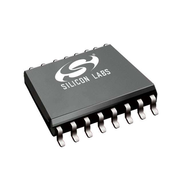
| 描述 | IC TXRX RS-232 W/SHTDWN 20-TQFNRS-232接口集成电路 3-5.5V 1Mbps Transceiver |
| 产品分类 | |
| 品牌 | Maxim Integrated |
| 产品手册 | |
| 产品图片 |
|
| rohs | 符合RoHS无铅 / 符合限制有害物质指令(RoHS)规范要求 |
| 产品系列 | 接口 IC,RS-232接口集成电路,Maxim Integrated MAX3225ECTP+- |
| 数据手册 | |
| 产品型号 | MAX3225ECTP+ |
| 产品培训模块 | http://www.digikey.cn/PTM/IndividualPTM.page?site=cn&lang=zhs&ptm=25703http://www.digikey.cn/PTM/IndividualPTM.page?site=cn&lang=zhs&ptm=25705 |
| 产品目录页面 | |
| 产品种类 | RS-232接口集成电路 |
| 传播延迟时间ns | 0.15 us |
| 供应商器件封装 | 20-TQFN (5x5) |
| 关闭 | Yes |
| 功能 | Transceiver |
| 包装 | 管件 |
| 协议 | RS232 |
| 双工 | 全 |
| 商标 | Maxim Integrated |
| 安装类型 | 表面贴装 |
| 安装风格 | SMD/SMT |
| 封装 | Tube |
| 封装/外壳 | 20-WQFN 裸露焊盘 |
| 封装/箱体 | TQFN-EP-20 |
| 工作温度 | 0°C ~ 70°C |
| 工作温度范围 | 0 C to + 70 C |
| 工作电源电压 | 3 V to 5.5 V |
| 工厂包装数量 | 60 |
| 应用说明 | 点击此处下载产品Datasheet点击此处下载产品Datasheet点击此处下载产品Datasheet点击此处下载产品Datasheet点击此处下载产品Datasheet点击此处下载产品Datasheet |
| 接收器滞后 | 500mV |
| 接收机数量 | 2 Receiver |
| 数据速率 | 1 Mbps |
| 最大工作温度 | + 70 C |
| 最小工作温度 | 0 C |
| 标准包装 | 1 |
| 激励器数量 | 2 Driver |
| 电压-电源 | 3 V ~ 5.5 V |
| 电源电流 | 1 mA |
| 类型 | 收发器 |
| 系列 | MAX3225E |
| 输入/输出端数量 | 8 |
| 零件号别名 | MAX3225E |
| 驱动器/接收器数 | 2/2 |







- 商务部:美国ITC正式对集成电路等产品启动337调查
- 曝三星4nm工艺存在良率问题 高通将骁龙8 Gen1或转产台积电
- 太阳诱电将投资9.5亿元在常州建新厂生产MLCC 预计2023年完工
- 英特尔发布欧洲新工厂建设计划 深化IDM 2.0 战略
- 台积电先进制程称霸业界 有大客户加持明年业绩稳了
- 达到5530亿美元!SIA预计今年全球半导体销售额将创下新高
- 英特尔拟将自动驾驶子公司Mobileye上市 估值或超500亿美元
- 三星加码芯片和SET,合并消费电子和移动部门,撤换高东真等 CEO
- 三星电子宣布重大人事变动 还合并消费电子和移动部门
- 海关总署:前11个月进口集成电路产品价值2.52万亿元 增长14.8%

PDF Datasheet 数据手册内容提取
MAX3224–MAX3227/ MAX3244/MAX3245 AVAILABLE 1µA Supply Current, 1Mbps, 3.0V to 5.5V, RS-232 Transceivers with AutoShutdown Plus ________________General Description _Next Generation Device Features The MAX3224–MAX3227/MAX3244/MAX3245 are 3V- ♦♦ For Smaller Packaging: powered EIA/TIA-232 and V.28/V.24 communications MAX3228/MAX3229: +2.5V to +5.5V RS-232 interfaces with automatic shutdown/wakeup features Transceivers in UCSP™ and high data-rate capabilities. ♦♦ For Low-Voltage or Data Cable Applications: All devices achieve a 1µA supply current using Maxim’s revolutionary AutoShutdown Plus™ feature. These MAX3380E/MAX3381E: +2.35V to +5.5V, 1µA, devices automatically enter a low-power shutdown 2 Tx/2 Rx RS-232 Transceivers with ±15kV ESD- mode when the RS-232 cable is disconnected or the Protected I/O and Logic Pins transmitters of the connected peripherals are inactive, ♦♦ For Integrated ESD Protection: and the UART driving the transmitter inputs is inactive MAX3222E/MAX3232E/MAX3237E/MAX3241E/ for more than 30 seconds. They turn on again when MAX3246E: ±15kV ESD-Protected, Down to 10nA, they sense a valid transition at any transmitter or receiv- +3.0V to +5.5V, Up to 1Mbps, True RS-232 er input. AutoShutdown Plus saves power without Transceivers (MAX3246E Available in UCSP) changes to the existing BIOS or operating system. The MAX3225/MAX3227/MAX3245 also feature MegaBaud™ operation, guaranteeing 1Mbps for high- _______________Ordering Information speed applications such as communicating with ISDN modems. The MAX3224/MAX3226/MAX3244 guarantee PART TEMP RANGE PIN-PACKAGE 250kbps operation. The transceivers have a proprietary MAX3224CPP+ 0°C to +70°C 20 PDIP low-dropout transmitter output stage enabling true RS- 232 performance from a +3.0V to +5.5V supply with a MAX3224CAP+ 0°C to +70°C 20 SSOP dual charge pump. The charge pump requires only four MAX3224CTP+ 0°C to +70°C 20 TQFN-EP* small 0.1µF capacitors for operation from a 3.3V supply. MAX3224CUP+ 0°C to +70°C 20 TSSOP The MAX3224–MAX3227 feature a logic-level output MAX3224EPP+ -40°C to +85°C 20 PDIP (READY) that asserts when the charge pump is regulat- ing and the device is ready to begin transmitting. MAX3224EAP+ -40°C to +85°C 20 SSOP MAX3224ETP+ -40°C to +85°C 20 TQFN-EP* All devices are available in a space-saving TQFN, TSSOP, and SSOP packages. MAX3224EUP+ -40°C to +85°C 20 TSSOP +Denotes a lead(Pb)-free/RoHS-compliant package. _______________F__u_n_c__ti_o_n_Aapl pDliiacgartaiomnss *EP = Exposed pad. Ordering Information continued at end of data sheet. Notebook, Subnotebook, and Palmtop Computers Cellular Phones _____________________Selector Guide Battery-Powered Equipment Handheld Equipment NO. OF GUARANTEED Auto- READY PART DRIVERS/ DATA RATE Shutdown OUTPUT Peripherals RECEIVERS (bps) Plus Printers MAX3224 2/2 250k ✔ ✔ MAX3225 2/2 1M ✔ ✔ MAX3226 1/1 250k ✔ ✔ MAX3227 1/1 1M ✔ ✔ MAX3244 3/5 250k — ✔ MAX3245 3/5 1M — ✔ Pin Configurations appear at end of data sheet. AutoShutdown Plus, MegaBaud, and UCSP are trademarks Functional Diagrams continued at end of data sheet. of Maxim Integrated Products, Inc. UCSP is a trademark of Maxim Integrated Products, Inc. For pricing, delivery, and ordering information, please contact Maxim Direct at 1-888-629-4642, or visit Maxim’s website at www.maximintegrated.com. 19-1289; Rev 5; 2/11
MAX3224–MAX3227/MAX3244/MAX3245 1µA Supply Current, 1Mbps, 3.0V to 5.5V, RS-232 Transceivers with AutoShutdown Plus ABSOLUTE MAXIMUM RATINGS VCCto GND..............................................................-0.3V to +6V Continuous Power Dissipation (TA= +70°C) V+ to GND (Note 1)..................................................-0.3V to +7V 16-Pin SSOP (derate 7.14mW/°C above +70°C).........571mW V- to GND (Note 1)...................................................+0.3V to -7V 20-PinPDIP (derate 11.11mW/°C above +70°C)............889mW V+ +⏐V-⏐(Note 1)................................................................+13V 20-PinTQFN (derate 21.3mW/°C above +70°C)........1702.1mW Input Voltages 20-Pin SSOP (derate 8.00mW/°C above +70°C).........640mW T_IN, FORCEON, FORCEOFFto GND................-0.3V to +6V 20-Pin TSSOP (derate 7.00mW/°C above +70°C).......559mW R_IN to GND....................................................................±25V 28-Pin SO (W) (derate 12.5mW/°C above +70°C).............1W Output Voltages 28-Pin SSOP (derate 9.52mW/°C above +70°C).........762mW T_OUT to GND.............................................................±13.2V Operating Temperature Ranges R_OUT, INVALID, READY to GND.........-0.3V to (VCC+ 0.3V) MAX32_ _C_ _.....................................................0°C to +70°C Short-Circuit Duration MAX32_ _E_ _..................................................-40°C to +85°C T_OUT to GND.......................................................Continuous Storage Temperature Range.............................-65°C to +160°C Lead Temperature (soldering, 10s).................................+300°C Soldering Temperature (reflow).......................................+260°C Note 1: V+ and V- can have maximum magnitudes of 7V, but their absolute difference cannot exceed 13V. Stresses beyond those listed under “Absolute Maximum Ratings” may cause permanent damage to the device. These are stress ratings only, and functional operation of the device at these or any other conditions beyond those indicated in the operational sections of the specifications is not implied. Exposure to absolute maximum rating conditions for extended periods may affect device reliability. ELECTRICAL CHARACTERISTICS (VCC= +3V to +5.5V, C1–C4 = 0.1µF, tested at 3.3V ±10%; C1 = 0.047µF, C2–C4 = 0.33µF, tested at 5.0V ±10%; TA= TMINto TMAX, unless otherwise noted. Typical values are at TA= +25°C.) PARAMETER SYMBOL CONDITIONS MIN TYP MAX UNITS DC CHARACTERISTICS(VCC= 3.3V or 5.0V, TA= +25°C) Supply Current, FORCEON = GND, FORCEOFF= VCC, 1 10 µA AutoShutdown Plus all R_IN idle, all T_IN idle Supply Current, Shutdown FORCEOFF= GND 1 10 µA Supply Current, AutoShutdown Plus Disabled FORCEON = FORCEOFF= VCC, no load 0.3 1 mA LOGIC INPUTS AND RECEIVER OUTPUTS Input Logic Threshold Low T_IN, FORCEON, FORCEOFF 0.8 V T_IN, FORCEON, VCC= 3.3V 2 Input Logic Threshold High V FORCEOFF VCC= 5.0V 2.4 Transmitter Input Hysteresis 0.5 V Input Leakage Current T_IN, FORCEON, FORCEOFF ±0.01 ±1 µA R_OUT (MAX3244/MAX3245), receivers Output Leakage Current ±0.05 ±10 µA disabled Output Voltage Low IOUT= 1.6mA 0.4 V Output Voltage High IOUT= -1.0mA VCC- 0.6 VCC- 0.1 V RECEIVER INPUTS Input Voltage Range -25 +25 V VCC= 3.3V 0.6 1.2 Input Threshold Low TA= +25°C V VCC= 5.0V 0.8 1.5 VCC= 3.3V 1.5 2.4 Input Threshold High TA= +25°C V VCC= 5.0V 1.8 2.4 Input Hysteresis 0.5 V Input Resistance TA= +25°C 3 5 7 kΩ 2 Maxim Integrated
MAX3224–MAX3227/MAX3244/MAX3245 1µA Supply Current, 1Mbps, 3.0V to 5.5V, RS-232 Transceivers with AutoShutdown Plus ELECTRICAL CHARACTERISTICS (continued) (VCC= +3V to +5.5V, C1–C4 = 0.1µF, tested at 3.3V ±10%; C1 = 0.047µF, C2–C4 = 0.33µF, tested at 5.0V ±10%; TA= TMINto TMAX, unless otherwise noted. Typical values are at TA= +25°C.) PARAMETER SYMBOL CONDITIONS MIN TYP MAX UNITS TRANSMITTER OUTPUTS All transmitter outputs loaded with 3kΩto Output Voltage Swing ±5 ±5.4 V ground Output Resistance VCC= V+ = V- = 0, transmitter outputs = ±2V 300 10M Ω Output Short-Circuit Current ±60 mA Output Leakage Current VCC= 0 or 3V to 5.5V, VOUT= ±12V, ±25 µA Transmitters disabled MOUSE DRIVEABILITY(MAX3244/MAX3245) T1IN = T2IN = GND, T3IN = VCC, T3OUT loaded with 3kΩto GND, Transmitter Output Voltage ±5 V T1OUT and T2OUT loaded with 2.5mA each AutoShutdown Plus(FORCEON = GND, FORCEOFF= VCC) Receiver Input Threshold to Positive threshold 2.7 Figure 4a V INVALIDOutput High Negative threshold -2.7 Receiver Input Threshold to Figure 4a -0.3 0.3 V INVALIDOutput Low INVALID, READY (MAX3224–MAX3227) IOUT= -1.6mA 0.4 V Output Voltage Low INVALID, READY (MAX3224–MAX3227) IOUT= -1.0mA VCC - 0.6 V Output Voltage High Receiver Positive or Negative tINVH VCC= 5V, Figure 4b 1 µs Threshold to INVALIDHigh Receiver Positive or Negative tINVL VCC= 5V, Figure 4b 30 µs Threshold to INVALIDLow Receiver or Transmitter Edge to Transmitters Enabled tWU VCC= 5V, Figure 5b (Note 2) 100 µs Receiver or Transmitter Edge to Transmitters Shutdown tAUTOSHDN VCC= 5V, Figure 5b (Note 2) 15 30 60 s Maxim Integrated 3
MAX3224–MAX3227/MAX3244/MAX3245 1µA Supply Current, 1Mbps, 3.0V to 5.5V, RS-232 Transceivers with AutoShutdown Plus TIMING CHARACTERISTICS—MAX3224/MAX3226/MAX3244 (VCC= +3V to +5.5V, C1–C4 = 0.1µF, tested at 3.3V ±10%; C1 = 0.047µF, C2–C4 = 0.33µF, tested at 5.0V ±10%; TA= TMINto TMAX, unless otherwise noted. Typical values are at TA= +25°C.) PARAMETER SYMBOL CONDITIONS MIN TYP MAX UNITS Maximum Data Rate RL= 3kΩ, CL= 1000pF, 250 kbps one transmitter switching tPHL 0.15 Receiver Propagation Delay R_IN to R_OUT, CL= 150pF µs tPLH 0.15 Receiver Output Enable Time Normal operation (MAX3244 only) 200 ns Receiver Output Disable Time Normal operation (MAX3244 only) 200 ns Transmitter Skew ⏐tPHL- tPLH ⏐ (Note 3) 100 ns Receiver Skew ⏐tPHL- tPLH ⏐ 50 ns VCC= 3.3V, TA= +25°C, CL= 150pF 6 30 Transition-Region Slew Rate RL= 3kΩto 7kΩ, to 1000pF V/µs more -a3sVu troe d+ 3frVom +3V to -3V CtoL 2=5 0105p0FpF 4 30 TIMING CHARACTERISTICS—MAX3225/MAX3227/MAX3245 (VCC= +3V to +5.5V, C1–C4 = 0.1µF, tested at 3.3V ±10%; C1 = 0.047µF, C2–C4 = 0.33µF, tested at 5.0V ±10%; TA= TMINto TMAX, unless otherwise noted. Typical values are at TA= +25°C.) PARAMETER SYMBOL CONDITIONS MIN TYP MAX UNITS RL= 3kΩ, CL= 1000pF, 250 one transmitter switching Maximum Data Rate VCC= 3.0V to 4.5V, RL= 3kΩ, 1000 kbps CL= 250pF, one transmitter switching VCC= 4.5V to 5.5V, RL= 3kΩ, 1000 CL= 1000pF, one transmitter switching tPHL 0.15 Receiver Propagation Delay R_IN to R_OUT, CL= 150pF µs tPLH 0.15 Receiver Output Enable Time Normal operation (MAX3245 only) 200 ns Receiver Output Disable Time Normal operation (MAX3245 only) 200 ns Transmitter Skew ⏐tPHL- tPLH ⏐ (Note 3) 25 ns Receiver Skew ⏐tPHL- tPLH ⏐ 50 ns VCC= 3.3V, TA= +25°C, Transition-Region Slew Rate RL= 3kΩto 7kΩ, CL= 150pF to 1000pF, 24 150 V/µs measured from +3V to -3V or -3V to +3V Note 2: A transmitter/receiver edge is defined as a transition through the transmitter/receiver input logic thresholds. Note 3: Transmitter skew is measured at the transmitter zero cross points. 4 Maxim Integrated
MAX3224–MAX3227/MAX3244/MAX3245 1µA Supply Current, 1Mbps, 3.0V to 5.5V, RS-232 Transceivers with AutoShutdown Plus __________________________________________Typical Operating Characteristics (VCC= +3.3V, 250kbps data rate, C1–C4 = 0.1µF, all transmitters loaded with 3kΩand CL, TA= +25°C, unless otherwise noted.) MAX3224/MAX3226 MAX3224/MAX3226 TRANSMITTER OUTPUT VOLTAGE MAX3224/MAX3226 OPERATING SUPPLY CURRENT vs. LOAD CAPACITANCE SLEW RATE vs. LOAD CAPACITANCE vs. LOAD CAPACITANCE NSMITTER OUTPUT VOLTAGE (V) ---3210123456 TT12 T(MRAANXS32M2I4T)T TINRGA NASTM 25IT0TkIbNpGs AT 1V5O.U6Tk+bps MAX3224-01 μSLEW RATE (V/s) 11114680246 +SLEW -SLEW MAX3224-02 SUPPLY CURRENT (mA) 1122334405050505 250kbps 12200kkbbppss MAX3224-03 A TR -4 VOUT- 2 5 T1 TRANSMITTING AT 250kbps -5 FOR DATA RATES UP TO 250kbps T2 (MAX3224) TRANSMITTING AT 15.6kbps -6 0 0 0 1000 2000 3000 4000 5000 0 1000 2000 3000 4000 5000 0 1000 2000 3000 4000 5000 LOAD CAPACITANCE (pF) LOAD CAPACITANCE (pF) LOAD CAPACITANCE (pF) MAX3225/MAX3227 MAX3225/MAX3227 TRANSMITTER OUTPUT VOLTAGE MAX3225/MAX3227 OPERATING SUPPLY CURRENT vs. LOAD CAPACITANCE SLEW RATE vs. LOAD CAPACITANCE vs. LOAD CAPACITANCE E (V) 57..05 MAX3224-04 8700 MAX3224-05 1980000 11(M TTARRXAA3NN2SS2MM5)IITTTTEERR AATT F1U/1L6L D DAATTAA R RAATTEE MAX3224-06 NSMITTER OUTPUT VOLTAG -22..055 11(LM OTTAARRXDAA3 NN=2SS 23MM5k)ΩIITT TT+EE2 CRRM LAAbTTp s2F1MU/1Lb6Lp D sDAAT1TA.15A. M5R RMAbATpbTEspEs 11MMbbppss μSLEW RATE (V/s) 6543200000 +SLEW -SLEW SUPPLY CURRENT (mA) 4365700000 LOA2DM b=p 3skΩ + CL 1Mbps 1.5Mbps A 20 R -5.0 T 10 1 TRANSMITTER AT 1Mbps 10 1 TRANSMITTER AT 62.5kbps (MAX3225) -7.5 0 0 0 500 1000 1500 2000 2500 0 500 1000 1500 2000 2500 0 500 1000 1500 2000 2500 LOAD CAPACITANCE (pF) LOAD CAPACITANCE (pF) LOAD CAPACITANCE (pF) MAX3225/MAX3227 MAX3224–MAX3227 MAX3224–MAX3227 TRANSMITTER SKEW vs. READY TURN-ON TIME READY TURN-OFF TIME LOAD CAPACITANCE vs. TEMPERATURE vs. TEMPERATURE 445050 11(M TTARRXAA3NN2SS2MM5)IITTTTEERR AATT 53102kbkbppss MAX3224-07 3368 MAX3224-08 211086000 MAX3224-09 TRANSMITTER SKEW (ns) 112233500505 LOAD = 3kΩ + CALVERAGE; 10 PARTS μREADY TURN-ON TIME (s) 232233408642 READY TURN-OFF TIME (ns) 111420864000000 5 22 20 0 20 0 0 500 1000 1500 2000 2500 3000 -40 -20 0 20 40 60 80 100 -40 -20 0 20 40 60 80 100 LOAD CAPACITANCE (pF) TEMPERATURE (°C) TEMPERATURE (°C) Maxim Integrated 5
MAX3224–MAX3227/MAX3244/MAX3245 1µA Supply Current, 1Mbps, 3.0V to 5.5V, RS-232 Transceivers with AutoShutdown Plus Typical Operating Characteristics (continued) (VCC= +3.3V, 250kbps data rate, C1–C4 = 0.1µF, all transmitters loaded with 3kΩand CL, TA= +25°C, unless otherwise noted.) MAX3244 MAX3244 TRANSMITTER OUTPUT VOLTAGE MAX3244 OPERATING SUPPLY CURRENT vs. LOAD CAPACITANCE SLEW RATE vs. LOAD CAPACITANCE vs. LOAD CAPACITANCE E (V) 456 VOUT+ MAX3224-10 1124 MAX3224-11 5600 12 TTRRAANNSSMMIITTTTEERR SA TA T2 5105k.6bkpbsps MAX3224-12 MITTER OUTPUT VOLTAG --210123 12 TTRRAANNSSMMIITTTTEERR SA TA T2 5105k.6bkpbsps μSLEW RATE (V/s) 14860 SUPPLY CURRENT (mA) 324000 250kbps 12200kkbbppss NS -3 TRA -4 VOUT- 2 10 -5 -6 0 0 0 1000 2000 3000 4000 5000 0 1000 2000 3000 4000 5000 0 1000 2000 3000 4000 5000 LOAD CAPACITANCE (pF) LOAD CAPACITANCE (pF) LOAD CAPACITANCE (pF) MAX3245 TRANSMITTER OUTPUT VOLTAGE MAX3245 vs. LOAD CAPACITANCE SLEW RATE vs. LOAD CAPACITANCE E (V) 57..05 MAX3224-13 6700 MAX3224-14 G A 2Mbps T 50 R OUTPUT VOL 2.05 12 TTRRAANNSSMMIITTTTEERR SA TA TF U1/L1L6 D DAA1T.T5AAM R RbAApTTsEE 1Mbps μW RATE (V/s) 4300 E E MITT -2.5 2Mbps 1.5Mbps 1Mbps SL 20 S N A TR -5.0 10 1 TRANSMITTER AT 1Mbps 2 TRANSMITTERS AT 62.5kbps -7.5 0 0 400 800 1200 1600 2000 0 400 800 1200 1600 2000 LOAD CAPACITANCE (pF) LOAD CAPACITANCE (pF) MAX3245 MAX3245 OPERATING SUPPLY CURRENT TRANSMITTER SKEW vs. vs. LOAD CAPACITANCE LOAD CAPACITANCE 100 50 9800 MAX3224-15 4405 MAX3224-16 PPLY CURRENT (mA) 46570000 2Mbps 1.5Mbps NSMITTER SKEW (ns) 22330505 SU 30 1Mbps TRA 15 20 10 1 TRANSMITTER AT FULL DATA RATE 10 5 2 TRANSMITTERS AT 1/16 DATA RATE 0 0 0 400 800 1200 1600 2000 0 1000 2000 3000 LOAD CAPACITANCE (pF) LOAD CAPACITANCE (pF) 6 Maxim Integrated
MAX3224–MAX3227/MAX3244/MAX3245 1µA Supply Current, 1Mbps, 3.0V to 5.5V, RS-232 Transceivers with AutoShutdown Plus Pin Description PIN MAX3224 MAX3225 MAX3226 MAX3244 NAME FUNCTION PDIP/ TQFN- MAX3227 MAX3245 SSIP/ EP TSSOP Ready to Transmit Output, Active High. READY is enabled high when 1 19 1 — READY V- goes below -4V and the device is ready to transmit. 2 1 2 28 C1+ Positive Terminal of Voltage-Doubler Charge-Pump Capacitor 3 20 3 27 V+ +5.5V Generated By the Charge Pump 4 2 4 24 C1- Negative Terminal of Voltage-Doubler Charge-Pump Capacitor 5 3 5 1 C2+ Positive Terminal of Inverting Charge-Pump Capacitor 6 4 6 2 C2- Negative Terminal of Inverting Charge-Pump Capacitor 7 5 7 3 V- -5.5V Generated By the Charge Pump 8, 17 6, 15 13 9, 10, 11 T_OUT RS-232 Transmitter Outputs 9, 16 7, 14 8 4–8 R_IN RS-232 Receiver Inputs 10, 15 8, 13 9 15–19 R_OUT TTL/CMOS Receiver Outputs Valid Signal Detector Output, Active Low. A logic-high indicates that 11 9 10 21 INVALID a valid RS-232 level is present on a receiver input. 12, 13 10, 11 11 12, 13, 14 T_IN TTL/CMOS Transmitter Inputs Force-On Input, Active High. Drive high to override AutoShutdown 14 12 12 23 FORCEON Plus, keeping transmitters and receivers on (FORCEOFF must be high) (Table 1). 18 16 14 25 GND Ground 19 17 15 26 VCC +3.0V to +5.5V Single Supply Voltage Force-Off Input, Active Low. Drive low to shut down transmitters, 20 18 16 22 FORCEOFF receivers (except R2OUTB), and charge pump. This overrides AutoShutdown Plus and FORCEON (Table 1). TTL/CMOS Noninverting Complementary Receiver Outputs. Always — — — 20 R2OUTB active. Exposed Pad (TQFN only). Solder the exposed pad to the ground, or — — — — EP leave unconnected. _______________Detailed Description than 5.5V, the charge pump is enabled; if the output voltages exceed 5.5V, the charge-pump is disabled. Dual Charge-Pump Voltage Converter Each charge pump requires a flying capacitor (C1, C2) The MAX3224–MAX3227/MAX3244/MAX3245’s internal and a reservoir capacitor (C3, C4) to generate the V+ power supply consists of a regulated dual charge and V- supplies. pump that provides output voltages of +5.5V (doubling The READY output (MAX3224–MAX3227) is low when charge pump) and -5.5V (inverting charge pump), over the charge pumps are disabled in shutdown mode. The the +3.0V to +5.5V range. The charge pump operates READY signal asserts high when V- goes below -4V. in discontinuous mode: if the output voltages are less Maxim Integrated 7
MAX3224–MAX3227/MAX3244/MAX3245 1µA Supply Current, 1Mbps, 3.0V to 5.5V, RS-232 Transceivers with AutoShutdown Plus POWER- FORCEOFF VCC MANAGEMENT UNIT OR FORCEON KEYBOARD INVALID CONTROLLER PROTECTION DIODE PREVIOUS MAX3244 RS-232 MAX3245 VCC Rx I UART 5kΩ Tx I/O GND SHDN = GND CPU CHIP WITH RS-232 UART a) OLDER RS-232: POWERED-DOWN UART DRAWS CURRENT FROM ACTIVE RECEIVER OUTPUT IN SHUTDOWN. VCC TO LOGIC μP TRANSITION DETECTOR Figure 1. Interface Under Control of PMU MAX3244 I MAX3245 PROTECTION DIODE RS-232 Transmitters R2OUTB The transmitters are inverting level translators that VCC convert CMOS-logic levels to 5.0V EIA/TIA-232 levels. The MAX3224/MAX3226/MAX3244 guarantee a Rx R2OUT R2IN 250kbps data rate (1Mbps for the MAX3225/MAX3227/ THREE-STATED MAX3245) with worst-case loads of 3kΩ in parallel with UART 5kΩ 1000pF, providing compatibility with PC-to-PC com- T1OUT munication software (such as LapLink®). Transmitters Tx T1IN can be paralleled to drive multiple receivers. Figure 1 shows a complete system connection. GND FORCEOFF = GND When FORCEOFFis driven to ground or when the Auto- Shutdown Plus circuitry senses that all receiver and transmitter inputs are inactive for more than 30sec, the b) NEW MAX3244/MAX3245: IN SHUTDOWN, R2OUTB IS USED TO MONITOR transmitters are disabled and the outputs go into a high- EXTERNAL DEVICES AND R2OUT IS THREE STATED, ELIMINATING A CURRENT impedance state. When powered off or shut down, the PATH THROUGH THE UART’S PROTECTION DIODE. outputs can be driven to ±12V. The transmitter inputs do not have pull-up resistors. Connect unused inputs to Figure 2. The MAX3244/MAX3245 detect RS-232 activity when GND or VCC. the UART and interface are shut down. LapLink is a registered trademark of Laplink Software, Inc. 8 Maxim Integrated
MAX3224–MAX3227/MAX3244/MAX3245 1µA Supply Current, 1Mbps, 3.0V to 5.5V, RS-232 Transceivers with AutoShutdown Plus Table 1. Output Control Truth Table R_OUT RECEIVER OR VALID (MAX3224/ R_OUT R2OUTB OPERATION TRANSMITTER FORCEON FORCEOFF RECEIVER T_OUT MAX3225/ (MAX3244/ (MAX3244/ STATUS EDGE WITHIN LEVEL MAX3226/ MAX3245) MAX3245) 30sec MAX3227) Shutdown X 0 X X High-Z Active High-Z Active (Forced Off) Normal Operation 1 1 X X Active Active Active Active (Forced On) Normal Operation 0 1 X Yes Active Active Active Active (AutoShutdown Plus) Shutdown (Auto- 0 1 X No High-Z Active Active Active Shutdown Plus) Normal INVALID* 1 Yes X Active Active Active Active Operation Normal INVALID* 1 X Yes Active Active Active Active Operation Shutdown INVALID* 1 No No High-Z Active Active Active Normal Operation INVALID* INVALID** Yes X Active Active Active Active (AutoShutdown) Shutdown INVALID* INVALID** No X High-Z Active High-Z Active (AutoShutdown™) X = Don’t care *INVALIDconnected to FORCEON **INVALIDconnected to FORCEON and FORCEOFF RS-232 Receivers The MAX3224–MAX3227/MAX3244/MAX3245 feature The receivers convert RS-232 signals to CMOS-logic an INVALID output that is enabled low when no valid output levels. The MAX3224–MAX3227 feature inverting RS-232 voltage levels have been detected on all receiv- outputs that always remain active (Table 1). The er inputs. Because INVALID indicates the receiver MAX3244/MAX3245 have inverting three-state outputs input’s condition, it is independent of FORCEON and that are high impedance when shut down (FORCEOFF FORCEOFFstates (Figures 3 and 4). = GND) (Table 1). AutoShutdown Plus Mode The MAX3244/MAX3245 feature an extra, always The MAX3224–MAX3227/MAX3244/MAX3245 achieve a active, noninverting output, R2OUTB. R2OUTB output 1µA supplycurrent with Maxim’s AutoShutdown Plus monitors receiver activity while the other receivers are feature, which operates when FORCEOFF is high and a high impedance, allowing Ring Indicator applications to FORCEON is low. When these devices do not sense a be monitored without forward biasing other devices valid signal transition on any receiver and transmitter connected to the receiver outputs. This is ideal for sys- input for 30sec, the on-board charge pumps are shut tems where VCC is set to ground in shutdown to down, reducing supply current to 1µA. This occurs if the accommodate peripherals such as UARTs (Figure 2). RS-232 cable is disconnected or if the connected AutoShutdown is a trademark of Maxim Integrated Products, Inc. Maxim Integrated 9
MAX3224–MAX3227/MAX3244/MAX3245 1µA Supply Current, 1Mbps, 3.0V to 5.5V, RS-232 Transceivers with AutoShutdown Plus +0.3V EDGE T_IN DETECT FORCEOFF S R_IN 30μs 30sec AUTOSHDN TIMER INVALID EDGE TIMER -0.3V R R_IN DETECT R INVALID ASSERTED IF ALL RECEIVER INPUTS ARE BETWEEN +0.3V AND -0.3V FOR AT LEAST 30μs. FORCEON Figure 3a. INVALIDFunctional Diagram, INVALIDLow Figure 3c. AutoShutdown Plus Logic +2.7V FORCEOFF POWERDOWN* FORCEON R_IN 30μs AUTOSHDN TIMER INVALID R -2.7V * POWERDOWN IS ONLY AN INTERNAL SIGNAL. IT CONTROLS THE OPERATIONAL STATUS OF INVALID DEASSERTED IF ANY RECEIVER INPUT HAS BEEN BETWEEN +2.7V AND -2.7V THE TRANSMITTERS AND THE POWER SUPPLIES. FOR LESS THAN 30μs. Figure 3b. INVALIDFunctional Diagram, INVALIDHigh Figure 3d. Power-Down Logic Table 2. INVALID Truth Table RS-232 SIGNAL INVALID HIGH PRESENT AT ANY INVALIDOUTPUT +2.7V RECEIVER INPUT LS INDETERMINATE E V Yes High E T L +0.3V No Low PU 0 INVALID LOW N ER I -0.3V V peripheral transmitters are turned off, and the UART dri- CEI INDETERMINATE E ving the transmitter inputs is inactive. The system turns R -2.7V on again when a valid transition is applied to any INVALID HIGH RS-232 receiver or transmitter input. As a result, the sys- tem saves power without changes to the existing BIOS or operating system. Figure 4a. Receiver Positive/Negative Thresholds for INVALID Figures 3a and 3b depict valid and invalid RS-232 receiver voltage levels. INVALID indicates the receiver between these states automatically based on the last input’s condition, and is independent of FORCEON and receiver or transmitter input edge received. FORCEOFF states. Figure 3 and Tables 1 and 2 sum- When shut down, the device’s charge pumps turn off, marize the operating modes of the MAX3224– V+ is pulled to VCC, V- is pulled to ground, the transmit- MAX3227/MAX3244/MAX3245 devices. FORCEON and ter outputs are high impedance, and READY FORCEOFF override AutoShutdown Plus circuitry. (MAX3224–MAX3227) is driven low. The time required When neither control is asserted, the IC selects to exit shutdown is typically 100µs (Figure 6). 10 Maxim Integrated
MAX3224–MAX3227/MAX3244/MAX3245 1µA Supply Current, 1Mbps, 3.0V to 5.5V, RS-232 Transceivers with AutoShutdown Plus RECEIVER }INVALID INPUTS REGION TRANSMITTER INPUTS TRANSMITTER OUTPUTS INVALID VCC tINVL OUTPUT tINVH 0 tAUTOSHDN tWU tAUTOSHDN tWU *VCC OUTPUT 0 V+ VCC 0 V- *MAX3224–MAX3227 Figure 4b. AutoShutdown Plus, INVALID,and READY Timing Diagram By connecting FORCEON to INVALID, the MAX3224– MAX3227/MAX3244/MAX3245 shut down when no valid POWER- MASTER SHDN LINE receiver level and no receiver or transmitter edge is MANAGEMENT UNIT detected for 30sec, and wake up when a valid receiver 0.1μF 1MΩ level or receiver or transmitter edge is detected. By connecting FORCEON and FORCEOFF to INVALID, the MAX3224–MAX3227/MAX3244/MAX3245 shutdown FORCEOFF FORCEON when no valid receiver level is detected and wake up when a valid receiver level is detected (same function- MAX3224 ality as AutoShutdown feature on MAX3221/MAX3223/ MAX3225 MAX3243). MAX3226 MAX3227 A mouse or other system with AutoShutdown Plus may MAX3244 need time to wake up. Figure 5 shows a circuit that MAX3245 forces the transmitters on for 100ms, allowing enough time for the other system to realize that the MAX3244/ MAX3245 is awake. If the other system outputs valid Figure 5. AutoShutdown Plus Initial Turn-On to Wake Up a RS-232 signal transitions within that time, the RS-232 Mouse or Another System ports on both systems remain enabled. Maxim Integrated 11
MAX3224–MAX3227/MAX3244/MAX3245 1µA Supply Current, 1Mbps, 3.0V to 5.5V, RS-232 Transceivers with AutoShutdown Plus Software-Controlled Shutdown transmitter is loaded with 3kΩ in parallel with 1000pF. If direct software control is desired, use INVALID to The transmitter outputs display no ringing or undesir- indicate DTR or Ring Indicator signal. Tie FORCEOFF able transients as they come out of shutdown. Note that and FORCEON together to bypass the AutoShutdown the transmitters are enabled only when the magnitude Plus so the line acts like a SHDNinput. of V- exceeds approximately -3V. __________Applications Information FORCEON = Capacitor Selection 5V/div FORCEOFF 0 The capacitor type used for C1–C4 is not critical for T1OUT proper operation; polarized or nonpolarized capacitors can be used. The charge pump requires 0.1µF capaci- tors for 3.3V operation. For other supply voltages, see Table 3 for required capacitor values. Do not use val- 2V/div ues smaller than those listed in Table 3. Increasing the 0 capacitor values (e.g., by a factor of 2) reduces ripple on the transmitter outputs and slightly reduces power consumption. C2, C3, and C4 can be increased without changing C1’s value. However, do not increase C1 5V/div VCC = 3.3V T2OUT C1–C4 = 0.1μF READY without also increasing the values of C2, C3, C4, 0 and CBYPASS, to maintain the proper ratios (C1 to 5μs/div the other capacitors). When using the minimum required capacitor values, Figure 6. Transmitter Outputs when Exiting Shutdown or make sure the capacitor value does not degrade Powering Up excessively with temperature. If in doubt, use capaci- tors with a larger nominal value. The capacitor’s equiva- VCC lent series resistance (ESR), which usually rises at low temperatures, influences the amount of ripple on V+ CBYPASS and V-. VCC Power-Supply Decoupling C1+ V+ In most circumstances, a 0.1µF VCC bypass capacitor C1 C3* C1- MAX3224 is adequate. In applications that are sensitive to power- MAX3225 supply noise, use a capacitor of the same value as C2+ MAX3226 V- charge-pump capacitor C1. Connect bypass capaci- C2 MAX3227 C4 tors as close to the IC as possible. C2- MAX3244 Transmitter Outputs MAX3245 when Exiting Shutdown T_ IN T_ OUT Figure 6 shows two transmitter outputs when exiting shutdown mode. As they become active, the two trans- mitter outputs are shown going to opposite RS-232 lev- R_ OUT R_ IN els (one transmitter input is high; the other is low). Each FORCEON 5kΩ 1000pF Table 3. Required Minimum Capacitance Values VCC FORCEOFF GND VCC C1, CBYPASS C2, C3, C4 (V) (µF) (µF) 3.0 to 3.6 0.1 0.1 *C3 CAN BE RETURNED TO VCC OR GND. 4.5 to 5.5 0.047 0.33 Figure 7. Loopback Test Circuit 3.0 to 5.5 0.22 1 12 Maxim Integrated
MAX3224–MAX3227/MAX3244/MAX3245 1µA Supply Current, 1Mbps, 3.0V to 5.5V, RS-232 Transceivers with AutoShutdown Plus High Data Rates The MAX3225/MAX3227/MAX3245 maintain the RS-232 The MAX3224/MAX3226/MAX3244 maintain the RS-232 ±5.0V minimum transmitter output voltage at data rates ±5.0V minimum transmitter output voltage even at high up to 1Mbps (MegaBaud). Figure 10 shows a loopback data rates. Figure 7 shows a transmitter loopback test test result with a single transmitter driven at 1Mbps and circuit. Figure 8 shows a loopback test result at all transmitters loaded with an RS-232 receiver in paral- 120kbps, and Figure 9 shows the same test at lel with 250pF. 250kbps. For Figure 8, all transmitters were driven Mouse Driveability simultaneously at 120kbps into RS-232 loads in parallel The MAX3244/MAX3245 are specifically designed to with 1000pF. For Figure 9, a single transmitter was dri- power serial mice while operating from low-voltage ven at 250kbps, and all transmitters were loaded with power supplies. They have been tested with leading an RS-232 receiver in parallel with 250pF. mouse brands from manufacturers such as Microsoft and Logitech. The MAX3244/MAX3245 successfully T1IN 5V/div T1IN 5V/div 5V/div T1OUT 5V/div T1OUT 5V/div 5V/div R1OUT R1OUT VCC = 3.3V VCC = 3.3V 2μs/div 200ns/div Figure 8. MAX3224/MAX3226/MAX3244 Loopback Test Result Figure 10. MAX3225/MAX3227/MAX3245 Loopback Test at 120kbps Result at 1Mbps 6 5 T1IN 5V/div AGE (V) 34 VCC = 3.0V VOUT+ T OL 2 V UT 1 VOUT+ P T1OUT 5V/div OUT 0 R -1 E T T -2 NSMI -3 VCC VOUT- R1OUT 5V/div TRA -4 VOUT- -5 VCC = 3.3V -6 0 1 2 3 4 5 6 7 8 9 10 2μs/div LOAD CURRENT PER TRANSMITTER (mA) Figure 9. MAX3224/MAX3226/MAX3244 Loopback Test Result Figure 11a. MAX324_ Transmitter Output Voltage vs. Load at 250kbps Current per Transmitter Maxim Integrated 13
MAX3224–MAX3227/MAX3244/MAX3245 1µA Supply Current, 1Mbps, 3.0V to 5.5V, RS-232 Transceivers with AutoShutdown Plus +3.3V 26 0.1μF 28 VCC 27 C1+ C1 V+ C3 0.1μF 24 0.1μF C1- COMPUTER SERIAL PORT 1 MAX3244 3 C2 C2+ MAX3245 V- C4 0.1μF 2 0.1μF C2- 14 T1IN T1OUT 9 +V LOGIC 13 T2IN T2OUT 10 +V INPUTS 12 T3IN T3OUT 11 -V GND 20 R2OUTB 19 R1OUT R1IN 4 Tx 5kΩ 18 R2OUT R2IN 5 LOGIC 5kΩ OUTPUTS 17 R3OUT R3IN 6 RS-232 INPUTS 5kΩ 16 R4OUT R4IN 7 5kΩ SERIAL 15 R5OUT R5IN 8 MOUSE 23 5kΩ FORCEON 22 VCC FORCEOFF TO POWER- 21 MANAGEMENT INVALID GND UNIT 25 Figure 11b. Mouse Driver Test Circuit 14 Maxim Integrated
MAX3224–MAX3227/MAX3244/MAX3245 1µA Supply Current, 1Mbps, 3.0V to 5.5V, RS-232 Transceivers with AutoShutdown Plus drove all serial mice tested and met their respective Interconnection with 3V and 5V Logic current and voltage requirements. The MAX3244/ The MAX3224–MAX3227/MAX3244/MAX3245 can MAX3245 dual charge pump ensures the transmitters directly interface with various 5V logic families, includ- will supply at least ±5V during worst-case conditions. ing ACT and HCT CMOS. See Table 4 for more informa- Figure 11a shows the transmitter output voltages under tion on possible combinations of interconnections. increasing load current. Figure 11b shows a typical Table 5 lists other Maxim 3.0V to 5.5V powered trans- mouse connection. ceivers. Table 4. Logic Family Compatibility with Various Supply Voltages SYSTEM VCCSUPPLY POWER-SUPPLY VOLTAGE COMPATIBILITY VOLTAGE(V) (V) 3.3 3.3 Compatible with all CMOS families 5 5 Compatible with all TTL and CMOS families 5 3.3 Compatible with ACT and HCT CMOS, and with AC, HC, or CD4000 CMOS Table 5. 3.0V to 5.5V Powered RS-232 Transceivers from Maxim SUPPLY NO. SUPPLY Auto- GUARANTEED VOLTAGE Auto- PART OF CURRENT Shutdown DATA RATE RANGE Shutdown Tx/Rx (µA) Plus (bps) (V) MAX3241 +3.0 to +5.5 3/5 300 — — 120k MAX3243 +3.0 to +5.5 3/5 1 — Yes 120k MAX3244 +3.0 to +5.5 3/5 1 Yes — 250k MAX3245 +3.0 to +5.5 3/5 1 Yes — 1M MAX3232 +3.0 to +5.5 2/2 300 — — 120k MAX3222 +3.0 to +5.5 2/2 300 — — 120k MAX3223 +3.0 to +5.5 2/2 1 — Yes 120k MAX3224 +3.0 to +5.5 2/2 1 Yes — 250k MAX3225 +3.0 to +5.5 2/2 1 Yes — 1M MAX3221 +3.0 to +5.5 1/1 1 — Yes 120k MAX3226 +3.0 to +5.5 1/1 1 Yes — 250k MAX3227 +3.0 to +5.5 1/1 1 Yes — 1M Maxim Integrated 15
MAX3224–MAX3227/MAX3244/MAX3245 1µA Supply Current, 1Mbps, 3.0V to 5.5V, RS-232 Transceivers with AutoShutdown Plus ___________________________________________________Typical Operating Circuits +3.3V +3.3V CBYPASS 0.1μF 15 CB0Y.P1AμSFS 26 C1 2 C1+ VCC V+ 3 C3 C1 28 C1+ VCC V+ 27 0.1μF 4 C1- 0.1μF 0.1μF 24 C1- C0.31μF MAX3226 5 C2+ MAX3227 V- 7 C4 1 C2+ MAX3244 V- 3 0.1 μC2F 6 C2- 0.1μF 0.1μCF2 2 C2- MAX3245 C0.41μF 11 T1IN T1OUT 13 14 T1IN T1OUT 9 9 R1OUT R1IN 8 13 T2IN T2OUT 10 5kΩ 12 T3IN T3OUT 11 TO POWER- 22 FORCEOFF 1 READY AUTOSHUTDOWN INVALID 10 MANAGEMENT AUTOSHUTDOWN INVALID 21 PLUS UNIT 23 FORCEON PLUS 12 FORCEON FORCEOFF 16 GND VCC 20 R2OUTB 14 19 R1OUT R1IN 4 +3.3V 5kΩ CBYPASS 0.1μF 19 2 VCC 3 18 R2OUT R2IN 5 C1+ V+ C1 C3 5kΩ 0.1μF 4 C1- 0.1μF MAX3224* 17 R3OUT R3IN 6 5 7 C2+ MAX3225* V- C4 0.1 μC2F 6 C2- 0.1μF 5kΩ 16 R4OUT R4IN 7 13 T1IN T1OUT 17 5kΩ TTL/CMOS RS-232 INPUTS OUTPUTS 12 T2IN T2OUT 8 15 R5OUT R5IN 8 5kΩ 15 R1OUT R1IN 16 TTL/CMOS 5kΩ RS-232 GND OUTPUTS INPUTS 25 10 R2OUT R2IN 9 5kΩ 1 READY AUTOSHUTDOWN INVALID 11 TO POWER- PLUS MANAGEMENT UNIT 14 FORCEON FORCEOFF 20 VCC GND *MAX3224/MAX3225 PINOUT REFERS TO PDIP/SSOP/TSSOP PACKAGES. 18 16 Maxim Integrated
MAX3224–MAX3227/MAX3244/MAX3245 1µA Supply Current, 1Mbps, 3.0V to 5.5V, RS-232 Transceivers with AutoShutdown Plus ___________________________________________________________Pin Configurations TOP VIEW + + READY 1 20 FORCEOFF READY 1 16 FORCEOFF C1+ 2 19 VCC C1+ 2 15 VCC V+ 3 18 GND V+ 3 14 GND C1- 4 17 T1OUT C1- 4 MAX3226 13 T1OUT MAX3227 C2+ 5 MAX3224 16 R1IN C2+ 5 12 FORCEON MAX3225 C2- 6 15 R1OUT C2- 6 11 T1IN V- 7 14 FORCEON V- 7 10 INVALID T2OUT 8 13 T1IN R1IN 8 9 R1OUT R2IN 9 12 T2IN SSOP R2OUT 10 11 INVALID DIP/SSOP/TSSOP + C2+ 1 28 C1+ N C2- 2 27 V+ O T1OUT R1IN R1OUT FORCE T1IN V- 3 26 VCC R1IN 4 25 GND 15 14 13 12 11 R2IN 5 24 C1- MAX3244 R3IN 6 MAX3245 23 FORCEON GND 16 10 T2IN R4IN 7 22 FORCEOFF VCC 17 9 INVALID R5IN 8 21 INVALID FORCEOFF 18 MAX3224 8 R2OUT T1OUT 9 20 R2OUTB MAX3225 READY 19 7 R2IN T2OUT 10 19 R1OUT *EP T3OUT 11 18 R2OUT V+ 20 + 6 T2OUT T3IN 12 17 R3OUT 1 2 3 4 5 T2IN 13 16 R4OUT C1+ C1- C2+ C2-. V- T1IN 14 15 R5OUT TQFN SO/SSOP *CONNECT EP TO GND. Maxim Integrated 17
MAX3224–MAX3227/MAX3244/MAX3245 1µA Supply Current, 1Mbps, 3.0V to 5.5V, RS-232 Transceivers with AutoShutdown Plus Ordering Information (continued) Chip Information PART TEMP RANGE PIN-PACKAGE PROCESS: BiCMOS MAX3225CPP+ 0°C to +70°C 20 PDIP MAX3225CAP+ 0°C to +70°C 20 SSOP Package Information MAX3225CTP+ 0°C to +70°C 20 TQFN-EP* For the latest package outline information and land patterns (footprints), go to www.maxim-ic.com/packages. Note that a MAX3225CUP+ 0°C to +70°C 20 TSSOP “+”, “#”, or “-” in the package code indicates RoHS status only. MAX3225EPP+ -40°C to +85°C 20 PDIP Package drawings may show a different suffix character, but the MAX3225EAP+ -40°C to +85°C 20 SSOP drawing pertains to the package regardless of RoHS status. MAX3225ETP+ -40°C to +85°C 20 TQFN-EP* PACKAGE PACKAGE OUTLINE LAND MAX3225EUP+ -40°C to +85°C 20 TSSOP TYPE CODE NO. PATTERN NO. MAX3225EUP/V+ -40°C to +85°C 20 TSSOP 16 SSOP A16+2 21-0056 90-0106 MAX3226CAE+ 0°C to +70°C 16 SSOP 20 SSOP A20+2 21-0056 90-0094 MAX3226EAE+ -40°C to +85°C 16 SSOP 20 TQFN-EP T2055+5 21-0140 90-0010 MAX3227CAE+ 0°C to +70°C 16 SSOP 20 TSSOP U20+2 21-0066 90-0116 MAX3227EAE+ -40°C to +85°C 16 SSOP 20 PDIP P20+3 21-0043 — MAX3244CWI+ 0°C to +70°C 28 SO (W) 28 SO (W) W28+6 21-0042 90-0109 MAX3244CAI+ 0°C to +70°C 28 SSOP 28 SSOP A28+1 21-0056 90-0095 MAX3244EWI+ -40°C to +85°C 28 SO (W) MAX3244EAI+ -40°C to +85°C 28 SSOP MAX3245CWI+ 0°C to +70°C 28 SO (W) MAX3245CAI+ 0°C to +70°C 28 SSOP MAX3245EWI+ -40°C to +85°C 28 SO (W) MAX3245EAI+ -40°C to +85°C 28 SSOP +Denotes a lead(Pb)-free/RoHS-compliant package. *EP = Exposed pad. /V denotes an automotive qualified part. 18 Maxim Integrated
MAX3224–MAX3227/MAX3244/MAX3245 1µA Supply Current, 1Mbps, 3.0V to 5.5V, RS-232 Transceivers with AutoShutdown Plus Revision History REVISION REVISION PAGES DESCRIPTION NUMBER DATE CHANGED 3 5/05 Added new packaging types (cid:1) 4 10/08 Added automotive qualified product information 1, 18 5 2/11 Changed all the parts in the Ordering Information to lead-free 1, 18 Maxim cannot assume responsibility for use of any circuitry other than circuitry entirely embodied in a Maxim product. No circuit patent licenses are implied. Maxim reserves the right to change the circuitry and specifications without notice at any time. The parametric values (min and max limits) shown in the Electrical Characteristics table are guaranteed. Other parametric values quoted in this data sheet are provided for guidance. Maxim Integrated 160 Rio Robles, San Jose, CA 95134 USA 1-408-601-1000 19 © 2011 Maxim Integrated The Maxim logo and Maxim Integrated are trademarks of Maxim Integrated Products, Inc.