ICGOO在线商城 > 开发板,套件,编程器 > 评估和演示板和套件 > MAX14840PMB1#

 Datasheet下载
- 型号: MAX14840PMB1#
- 制造商: Maxim
- 库位|库存: xxxx|xxxx
- 要求:
| 数量阶梯 | 香港交货 | 国内含税 |
| +xxxx | $xxxx | ¥xxxx |
查看当月历史价格
查看今年历史价格
MAX14840PMB1#产品简介:
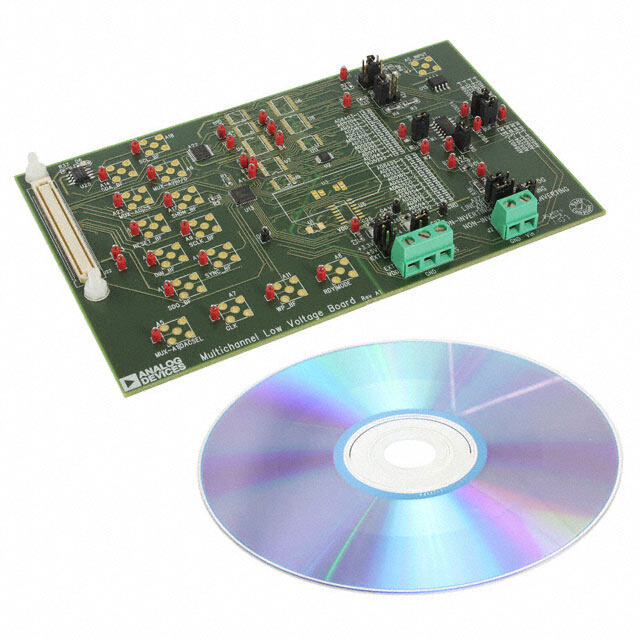
ICGOO电子元器件商城为您提供MAX14840PMB1#由Maxim设计生产,在icgoo商城现货销售,并且可以通过原厂、代理商等渠道进行代购。 MAX14840PMB1#价格参考。MaximMAX14840PMB1#封装/规格:评估和演示板和套件, MAX14840E 收发器,RS-485 接口 Evaluation Board。您可以下载MAX14840PMB1#参考资料、Datasheet数据手册功能说明书,资料中有MAX14840PMB1# 详细功能的应用电路图电压和使用方法及教程。
Maxim Integrated(现为Analog Devices旗下品牌)的型号为MAX14840PMB1#的设备属于评估和演示板套件,主要用于评估MAX14840高性能模拟前端(AFE)芯片的性能。该评估板适用于工业自动化、过程控制、测试与测量设备等精密模拟信号采集系统。

MAX14840PMB1#评估板可帮助工程师快速验证MAX14840在多种工业场景下的性能,例如温度、压力、流量等传感器信号的高精度采集。其应用场景包括PLC(可编程逻辑控制器)、智能变送器、工业I/O模块以及现场仪表设备等。

该评估板支持多种输入信号类型,具备高分辨率和低噪声特性,适合用于要求严苛的工业环境中的信号调理和数据采集系统开发与测试。通过该套件,用户可深入了解MAX14840的性能参数、配置方式以及与主控制器的接口通信,从而加速产品开发进程。
| 参数 | 数值 |
| 产品目录 | 编程器,开发系统嵌入式解决方案 |
| 描述 | MODULE PERIPHERAL FOR MAX14840界面开发工具 MAX14840PMB1 Peripheral Module |
| 产品分类 | |
| 品牌 | Maxim Integrated |
| 产品手册 | |
| 产品图片 |
|
| rohs | RoHS 合规性豁免不受无铅要求限制 / 符合限制有害物质指令(RoHS)规范要求 |
| 产品系列 | 模拟与数字IC开发工具,界面开发工具,Maxim Integrated MAX14840PMB1#- |
| 数据手册 | |
| 产品型号 | MAX14840PMB1# |
| 主要属性 | - |
| 主要用途 | 接口,收发器,RS-485 |
| 产品 | Peripheral Module |
| 产品种类 | 界面开发工具 |
| 使用的IC/零件 | MAX14840E |
| 其它名称 | MAX14840PMB1 |
| 商标 | Maxim Integrated |
| 嵌入式 | - |
| 工作电源电压 | 3.3 V |
| 工作电源电流 | 1.5 mA |
| 工具用于评估 | MAX14840E |
| 工具箱 | /product-detail/zh/MAXPMBAE1%23/MAXPMBAE1%23-ND/3758899 |
| 应用说明 | |
| 所含物品 | 板 |
| 接口类型 | UART |
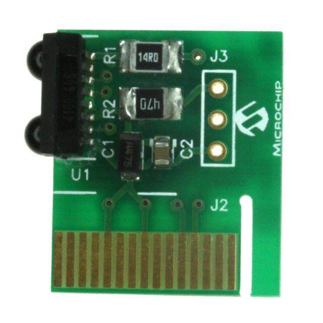
| 描述/功能 | MAX14840PMB1 peripheral module provides the necessary hardware to interface the MAX14840E RS-485 |
| 最大工作温度 | + 125 C |
| 最小工作温度 | - 40 C |
| 标准包装 | 1 |
| 用于 | FPGA/CPU Expansion Port with Pmod Standard |
| 类型 | RS-485 |
| 系列 | MAX14840E |
| 辅助属性 | - |
| 零件号别名 | 90-14840#PM1 MAX14840E |


PDF Datasheet 数据手册内容提取
19-6338; Rev 0; 5/12 MAX14840PMB1 Peripheral Module General Description Features The MAX14840PMB1 peripheral module provides the S Half-Duplex RS-485 Transceivers necessary hardware to interface the MAX14840E RS-485 S 40Mbps Maximum Data Rate transceiver to any system that utilizes PmodTM-compatible S Large (170mV) Receiver Hysteresis expansion ports configurable for a UART interface. The IC is a +3.3V ESD-protected transceiver intended for S Symmetrical Fail-Safe Receiver Input half-duplex RS-485 communication up to 40Mbps*. These S Hot-Swap Capability transceivers are optimized for high speeds over extended S Short-Circuit-Protected Outputs cable runs, while maximizing tolerance to noise. S Thermal Self-Protection The IC features symmetrical fail-safe and larger receiver hysteresis, providing improved noise rejection and S Extended ESD Protection for RS-485 I/O Pins improved recovered signals in high-speed and long- S 6-Pin Pmod-Compatible Connector (Pmod cable applications. Interface Type 4 UART) *The maximum communication speed of this module S Example Software Written in C for Portability is generally less than 10Mbps due to the presence of S RoHS Compliant current-limiting resistors on the data lines of this module and possibly also the host board. S Proven PCB Layout Refer to the MAX14840E IC data sheet for detailed infor- S Fully Assembled and Tested mation regarding operation of the IC. Ordering Information appears at end of data sheet. MAX14840PMB1 Peripheral Module Pmod is a trademark of Digilent Inc. _________________________________________________________________ Maxim Integrated Products 1 For pricing, delivery, and ordering information, please contact Maxim Direct at 1-888-629-4642, or visit Maxim’s website at www.maxim-ic.com.
MAX14840PMB1 Peripheral Module Component List DESIGNATION QTY DESCRIPTION DESIGNATION QTY DESCRIPTION 1FF Q10%, 10V X7R ceramic JP1 1 2-pin straight male header C1 1 capacitor (0603) R1–R4 4 150I Q5% resistors (0603) TDK C1608X7R1A105K R5 1 120I Q5% resistor (1206) 0.1FF Q10%, 16V X7R ceramic 40Mbps, +3.3V, RS-485 half- C2 1 capacitor (0603) U1 1 duplex transceiver (8 SO) Murata GRM188R71C104KA01D Maxim MAX14840EASA+ J1 1 6-pin right-angle male header — 1 Shorting jumper 2-position terminal block — 1 PCB: EPCB14840EPM1 J2 1 On-Shore Technology ED500/2DS Component Suppliers SUPPLIER PHONE WEBSITE Murata Electronics North America, Inc. 770-436-1300 www.murata-northamerica.com On-Shore Technology, Inc. 480-921-3000 www.on-shore.com TDK Corp. 847-803-6100 www.component.tdk.com Note: Indicate that you are using the MAX14840PMB1 when contacting these component suppliers. Detailed Description Table 1. Connector J1 (UART Communication) PIN SIGNAL DESCRIPTION UART Interface Receiver-enable input. This active-low The MAX14840PMB1 peripheral module can interface 1 RE pin enables the half-duplex receiver. to the host by plugging directly into a Pmod-compatible port (configured for UART ) through connector J1. Driver input. This pin carries the transmit 2 DI data from the Pmod system’s UART Connector J1 provides connection of the module to the transmitter to a connected receiver. Pmod host through an interface similar to the Pmod UART Type 4 standard recommended by Digilent. The Receiver output. This pin carries the transmit driver and receive pin assignment are the same 3 RO half-duplex receive data to the Pmod as the standard. However, the CTS and RTS signals system’s UART receiver. are replaced by half-duplex driver- and receiver-enable Driver-output-enable input. This active- signals. See Table 1. 4 DE high pin enables the half-duplex Connector J2 provides the RS-485 positive and negative transmitter. signal pair. See Table 2. 5 GND Ground 6 VCC Power supply Table 2. Connector J2 PIN SIGNAL DESCRIPTION 1 RS485-A Noninverting RS-485 signal 2 RS485-B Inverting RS-485 signal _________________________________________________________________ Maxim Integrated Products 2
MAX14840PMB1 Peripheral Module Connector JP1 (Termination Select) The software project (for the SDK) contains several This jumper port optionally inserts a 120I termination source files intended to accelerate customer evalu- resistor across the transmit-positive and negative nets. ation and design. These include a base application The JP1 jumper should be installed at the endpoints of (maximModules.c) that demonstrates module functionality, the RS-485 network, and not at the midpoints. and which uses an API interface (maximDeviceSpecific Utilities.c) to set and access Maxim device functions within Software and FPGA Code a specific module. Example software and drivers are available that execute The source code is written in standard ANSI C format, and directly without modification on several FPGA devel- all API documentation including theory/operation, register opment boards that support an integrated or synthe- description, and function prototypes are documented in sized microprocessor. These boards include the Digilent the API interface file (maximDeviceSpecificUtilities.h & .c). Nexys 3, Avnet LX9, and Avnet ZEDBoard, although other platforms can be added over time. Maxim provides The complete software kit is available for download at complete Xilinx ISE projects containing HDL, Platform www.maxim-ic.com. Quick start instructions are also Studio, and SDK projects. In addition, a synthesized bit available as a separate document. stream, ready for FPGA download, is provided for the demonstration application. VCC VCC C1 C2 1uF 0.1uF RS485-B GND GND 1 J2 JP1 2 1 J1 U1 A R1 150 RE 1 8 1 RO VCC VCC 2 2 R2 150 DI 2 7 R5 B 3 R3 150 RO RE B 120 R4 150 DE 3 6 4 DE A 5 GND 4 5 RS485-A DI GND GND 6 VCC MAX14840E Figure 1. MAX14840PMB1 Peripheral Module Schematic Figure 2. MAX14840PMB1 Peripheral Module Component Placement Guide—Component Side _________________________________________________________________ Maxim Integrated Products 3
MAX14840PMB1 Peripheral Module Figure 3. MAX14840PMB1 Peripheral Module PCB Layout—Component Side Figure 4. MAX14840PMB1 Peripheral Module PCB Layout—Inner Layer 1 (Ground) Figure 5. MAX14840PMB1 Peripheral Module PCB Layout—Inner Layer 2 (Power) _________________________________________________________________ Maxim Integrated Products 4
MAX14840PMB1 Peripheral Module Figure 6. MAX14840PMB1 Peripheral Module PCB Layout—Solder Side Figure 7. MAX14840PMB1 Peripheral Module Component Placement Guide—Solder Side _________________________________________________________________ Maxim Integrated Products 5
MAX14840PMB1 Peripheral Module Ordering Information PART TYPE MAX14840PMB1# Peripheral Module #Denotes RoHS compliant. _________________________________________________________________ Maxim Integrated Products 6
MAX14840PMB1 Peripheral Module Revision History REVISION REVISION PAGES DESCRIPTION NUMBER DATE CHANGED 0 5/12 Initial release — Maxim cannot assume responsibility for use of any circuitry other than circuitry entirely embodied in a Maxim product. No circuit patent licenses are implied. Maxim reserves the right to change the circuitry and specifications without notice at any time. Maxim Integrated Products, 120 San Gabriel Drive, Sunnyvale, CA 94086 408-737-7600 7 © 2012 Maxim Integrated Products Maxim is a registered trademark of Maxim Integrated Products, Inc.