
 Datasheet下载
- 型号: MA4P4301F-1091T
- 制造商: M/A-COM
- 库位|库存: xxxx|xxxx
- 要求:
| 数量阶梯 | 香港交货 | 国内含税 |
| +xxxx | $xxxx | ¥xxxx |
查看当月历史价格
查看今年历史价格
MA4P4301F-1091T产品简介:
ICGOO电子元器件商城为您提供MA4P4301F-1091T由M/A-COM设计生产,在icgoo商城现货销售,并且可以通过原厂、代理商等渠道进行代购。 MA4P4301F-1091T价格参考¥79.17-¥112.98。M/A-COMMA4P4301F-1091T封装/规格:二极管 - 射频, RF Diode PIN - Single 100V 5W 。您可以下载MA4P4301F-1091T参考资料、Datasheet数据手册功能说明书,资料中有MA4P4301F-1091T 详细功能的应用电路图电压和使用方法及教程。
M/A-COM Technology Solutions 的 MA4P4301F-1091T 是一款高性能射频肖特基二极管,广泛应用于高频、低功耗的射频与微波电路中。该器件采用先进的平面掺杂技术,具有低正向压降、快速开关速度和优异的射频检波性能,适用于对信号灵敏度和效率要求较高的场景。

典型应用场景包括:
1. 射频检波器:用于无线通信系统中的信号强度检测(RSSI),如基站、微波链路和雷达系统;
2. 混频器电路:在射频前端中实现频率转换,常见于卫星通信、5G基础设施及点对点无线传输设备;
3. 低功率整流:适用于能量收集或无源射频识别(RFID)系统中的微型整流电路;
4. 测试与测量设备:用于高频探头、网络分析仪等精密仪器中的信号采样与监测;
5. 航空航天与国防电子:在雷达接收机、电子战系统和通信模块中提供高可靠性射频处理能力。

MA4P4301F-1091T 采用表面贴装封装(SOD-323),体积小巧,适合高密度PCB布局,同时具备良好的温度稳定性和长期可靠性。其工作频率范围宽,可覆盖从数百MHz到数十GHz的频段,是现代高频电子系统中理想的无源半导体元件之一。
| 参数 | 数值 |
| 产品目录 | |
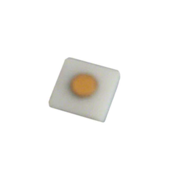
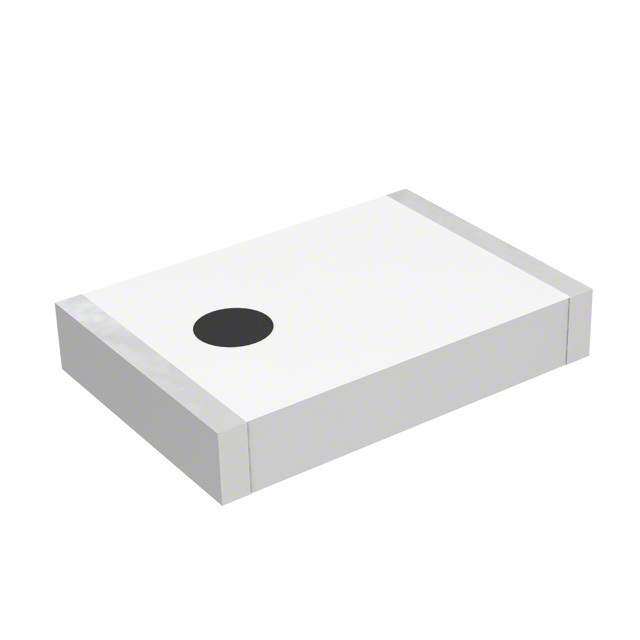
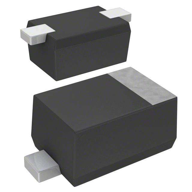
| 描述 | DIODE PIN CERAMIC SIPIN 二极管 .1-1000MHz 2.0pF Max Vr 100Vdc |
| 产品分类 | RF 二极管分离式半导体 |
| 品牌 | MACOMM/A-Com Technology Solutions |
| 产品手册 | |
| 产品图片 |
|
| rohs | 符合RoHS无铅 / 符合限制有害物质指令(RoHS)规范要求 |
| 产品系列 | 二极管与整流器,PIN 二极管,MACOM MA4P4301F-1091T- |
| 数据手册 | |
| 产品型号 | MA4P4301F-1091TMA4P4301F-1091T |
| 不同 If、F时的电阻 | 1 欧姆 @ 100mA,100MHz |
| 不同 Vr、F时的电容 | - |
| 二极管类型 | PIN - 单 |
| 产品种类 | PIN 二极管 |
| 供应商器件封装 | - |
| 其它名称 | 1465-1229-6 |
| 功率耗散 | 5 W |
| 功率耗散(最大值) | 5W |
| 包装 | Digi-Reel® |
| 反向电压 | 100 V |
| 商标 | MACOM |
| 封装 | Reel |
| 封装/外壳 | 2-SMD |
| 封装/箱体 | MELF-1072 |
| 工厂包装数量 | 500 |
| 最大串联电阻(中频最大时) | 1 Ohms |
| 最大二极管电容 | 2 pF |
| 最大工作温度 | + 175 C |
| 最小工作温度 | - 55 C |
| 标准包装 | 1 |
| 正向电压 | 1.2 V |
| 电压-峰值反向(最大值) | 100V |
| 电流-最大值 | - |
| 系列 | SMPP |
| 载流子寿命 | 15 us |


- 商务部:美国ITC正式对集成电路等产品启动337调查
- 曝三星4nm工艺存在良率问题 高通将骁龙8 Gen1或转产台积电
- 太阳诱电将投资9.5亿元在常州建新厂生产MLCC 预计2023年完工
- 英特尔发布欧洲新工厂建设计划 深化IDM 2.0 战略
- 台积电先进制程称霸业界 有大客户加持明年业绩稳了
- 达到5530亿美元!SIA预计今年全球半导体销售额将创下新高
- 英特尔拟将自动驾驶子公司Mobileye上市 估值或超500亿美元
- 三星加码芯片和SET,合并消费电子和移动部门,撤换高东真等 CEO
- 三星电子宣布重大人事变动 还合并消费电子和移动部门
- 海关总署:前11个月进口集成电路产品价值2.52万亿元 增长14.8%


PDF Datasheet 数据手册内容提取
MA4P MELF & HIPAX Series High Power PIN Diodes V16 Features Package Styles High Power Handling Low Loss / Low Distortion Voltage Ratings up to 1000 Volts Passivated Chip for Low Leakage Current 401 & 402 Low Theta (θ) Due to Full Face Chip Bonding Leadless Low Inductance MELF Packages Various Package Options Available as Chips Fully RoHS Compliant Non-Magnetic Packages Available for MRI 1072 & 1091 Description Applications The MELF and HIPAX PIN diode series are HIPAX PIN diodes are designed for use in a wide designed for usage in switch and attenuator variety of switch and attenuator applications from applications requiring high power handling and low HF through UHF frequencies and at power levels distortion. These diodes incorporate a fully above 1 kW, CW. The internal chip as well as each passivated PIN diode chip resulting in an extremely diode assembly has been comprehensively tested low reverse bias leakage current. The and characterized to ensure predictable and semiconductor technology utilized in the MELF and repeatable performance. HIPAX families draws on MACOM ’s substantial experience in PIN diode design and wafer fabrication. The result is a device which has a thick Design Recommendations I-region and long carrier lifetime while maintaining Low Distortion Attenuators low series resistance and capacitance values. The MA4P4301B chips of the MELF and HIPAX PIN diodes are Surface Mount Switches enclosed in a rugged ceramic package and is full MA4P7101F face bonded to metal pins on both the anode and Cellular Radio Antenna Switches cathode. The result is a low loss PIN diode with low MA4P1200, MA4P1250 thermal resistance due to symmetrical thermal paths. The parts are offered in either magnetic or non-magnetic, HIPAX (axial leaded) or MELF (Metal Electrode Leadless Faced) surface mount packages Absolute Maximum Ratings for MRI applications. The MELF is a rectangular T = +25°C (Unless Otherwise Noted)1 SMQ, package which is designed for high volume A tape and reel assembly. This easy to use package Parameter Absolute Maximum design makes automatic pick and place, indexing and assembly, extremely easy. The parallel flat sur- DC Reverse Voltage (V ) (See Tables) R faces are suitable for most key jaw or vacuum pick- Operating Chip Junction up techniques. All of the solderable surfaces are tin -55°C to +175°C Temperature plated and compatible with industry standard reflow and vapor phase soldering processes. See Applica- Storage Temperature -55°C to +200°C tion Note M538 for a typical solder reflow profile. Installation Temperature +280°C for 30 Seconds ESD Class 1A, HBM Many of MACOM’s HIPAX PIN diodes are also available as chips. Please consult the “Silicon PIN Chip Datasheet” for availability and specifications. Notes 1. Operation of this device above any one of these parameters may cause permanent damage. 111 MACOM Technology Solutions Inc. (MACOM) and its affiliates reserve the right to make changes to the product(s) or information contained herein without notice. Visit www.macom.com for additional data sheets and product information. For further information and support please visit: https://www.macom.com/support
MA4P MELF & HIPAX Series High Power PIN Diodes V16 MA4P1000 Series Electrical Specifications @ T = +25°C A C V R R T R S P Total Capacitance Reverse Voltage Series Resistance Parallel Resistance Part # pF VDC W kW (NM Indicates Non- V = 50 V, 1 MHz I = 10 mA I = 50 mA, 100 MHz V = 0 V, 100 MHz R R F R Magnetic) Typ. Max. Min. Max. Typ. Max. Min. MA4P1200 - 401T 1.2 1.5 MA4P1200NM - 401T 1.2 1.5 MA4P1250 -1072T 0.8 1.2 50 100 0.5 0.75 5 MA4P1250NM -1072T 0.8 1.2 MA4P1450 -1091T 1.8 2.5 V T Forward Bias Reverse Bias F L Forward Voltage Carrier Lifetime Harmonic Distortion Harmonic Distortion (Max. I @ 1V ≤ R(2a/a) * R(3a/a) R(2a/a) – R(3a/a) Part # Forward P = 30 W, 100 MHz P = 0 dBm, V = 0 V, (NM Indicates Non- I = 50 mA I = 10 mA, I = 6 mA IN IN R F F R I = 50 mA 100 MHz Magnetic) F Typ. Max. Min. Typ. Min. Typ. Min. Typ. MA4P1200 - 401T MA4P1200NM - 401T MA4P1250 -1072T 0.85 1.0 2 8 80 90 60 70 MA4P1250NM-1072T MA4P1450 -1091T *Notes: 1.) “NM” in the base part number signifies non-magnetic package. 2.) “T” suffix denotes tape and reel Power Dissipation and Thermal Resistance Ratings @ T = +25°C A MA4P1200(NM)-401T MA4P1250(NM)-1072T MA4P1450-1091T Package Condition Style P θ P θ P θ DISS JC DISS JC DISS JC No Heatsink 1.5 W — — — — B 15°C/W Axial Lead Lead Length 1/4" 5.5 W — — — — No Heatsink — 6 W 10 W F 15°C/W 5°C/W MELF Infinite Heatsink — 18 W 30 W 222 MACOM Technology Solutions Inc. (MACOM) and its affiliates reserve the right to make changes to the product(s) or information contained herein without notice. Visit www.macom.com for additional data sheets and product information. For further information and support please visit: https://www.macom.com/support
MA4P MELF & HIPAX Series High Power PIN Diodes V16 Typical Performance Curves @ T = +25°C A MA4P1200 Series Capacitance vs. Frequency & Reverse Bias Series Resistance @ 100 MHz vs. Forward Current stance acitance Resi Ω CappF s e ri e S MHz Frequency Forward Current Parallel Resistance vs. Frequency & Reverse Bias Heatsink Temperature vs. Max. Power Dissipation n o ce ati n p a si st s Resi Ω er Di tts el owWa rall m P Pa mu xi a M MHz °C Frequency Heatsink Temperature 333 MACOM Technology Solutions Inc. (MACOM) and its affiliates reserve the right to make changes to the product(s) or information contained herein without notice. Visit www.macom.com for additional data sheets and product information. For further information and support please visit: https://www.macom.com/support
MA4P MELF & HIPAX Series High Power PIN Diodes V16 Typical Performance Curves @ T = +25°C A MA4P1250 Series Series Resistance @ 100 MHz vs. Forward Current Capacitance vs. Frequency & Reverse Bias e stanc ance Resi Ω pacit pF s a e C ri e S MHz Forward Current Frequency Parallel Resistance vs. Frequency & Reverse Bias Carrier Lifetime vs. Forward Bias Current e e m stanc Lifeti si r e Ω e R ri el ar all C r a P MHz Frequency Forward Current 444 MACOM Technology Solutions Inc. (MACOM) and its affiliates reserve the right to make changes to the product(s) or information contained herein without notice. Visit www.macom.com for additional data sheets and product information. For further information and support please visit: https://www.macom.com/support
MA4P MELF & HIPAX Series High Power PIN Diodes V16 Typical Performance Curves @ T = +25°C A MA4P1450 Series Series Resistance @ 100 MHz vs. Forward Current Capacitance vs. Frequency and Reverse Bias ce e n c a n sist citapF e a R Ω p s Ca e ri e S MHz Frequency Forward Current Parallel Resistance vs. Frequency and Reverse Bias e c n a t s si e Ω R el all r a P MHz Frequency 555 MACOM Technology Solutions Inc. (MACOM) and its affiliates reserve the right to make changes to the product(s) or information contained herein without notice. Visit www.macom.com for additional data sheets and product information. For further information and support please visit: https://www.macom.com/support
MA4P MELF & HIPAX Series High Power PIN Diodes V16 MA4P4000 - MA4P7100 Series Electrical Specifications @ T = +25°C A MA4P4000 MA4P4300 MA4P7000 MA4P7100 Parameter Symbol Condition Series Series Series Series Maximum Series Resistance R I = 100 mA 0.5 Ω 1.0 Ω 0.9 Ω 0.5 Ω S F Maximum Total Capacitance C V = 100 V 2.2 pF 2.0 pF 0.7 pF 1.0 pF T R Minimum Parallel Resistance R V = 100 V 20 kΩ 50 kΩ 200 kΩ 100 kΩ P R Minimum Carrier Lifetime T I = 10 mA 20 µs 15 µs 5 µs 2.5 µs L F Maximum Forward Voltage V I = 100 mA 1.0 V 1.2 V 1.0 V 1.0 V F F Maximum Reverse Current I At max. rated voltage 1 µA 1 µA 1 µA 1 µA R Nominal I-Region Width μ — 175 µm 300 µm 175 µm 100 µm Maximum Reverse Voltage Rating ( V ) R Maximum Reverse MA4P4000 MA4P4300 MA4P7000 MA4P7100 Voltage Rating Series Series Series Series MA4P4001B-402 MA4P4301B-402 MA4P7101B-401T 100 V MA4P4001BNM-402 MA4P7001F-1072T MA4P4301F-1091T MA4P7101F-1072T MA4P4001F-1091T MA4P4002B-402 MA4P7002B-401T MA4P7102B-401T 200 V MA4P4302B-402 MA4P4002F-1091T MA4P7002F-1072T MA4P7102F-1072T MA4P7104B-401T 400 V — — — MA4P7104F-1072T MA4P4006F-1091T MA4P7006B-401T 600 V — — MA4P4006B-402 MA4P7006F-1072T *Notes: 1.) “NM” in the base part number signifies non-magnetic package. 2.) “T” suffix denotes tape and reel. MA4P4000 MA4P4300 MA4P7000 MA4P7100 Package Condition Series Series Series Series Style P θ P θ P θ P θ DISS JC DISS JC DISS JC DISS JC 1/4” Lead Length 12 W 12.5°C/W 10 W 15°C/W 5 W 30°C/W 6 W 25°C/W B Axial Leaded No Heatsink 2.5 W — 2.5 W — 1.5 W — 1.5 W — F Infinite Heatsink 7.5 W 20°C/W 5 W 30°C/W 10 W 15°C/W 11.5 W 13°C/W MELF Both B and F Single 1 µs pulse 100 kW — 100 kW — 15 kW — 15 kW — Both B and F Single 100 µs 5 kW 0.03°C/W 5 kW 0.03°C/W 300 W 0.5°C/W 300 W 0.5°C/W 666 MACOM Technology Solutions Inc. (MACOM) and its affiliates reserve the right to make changes to the product(s) or information contained herein without notice. Visit www.macom.com for additional data sheets and product information. For further information and support please visit: https://www.macom.com/support
MA4P MELF & HIPAX Series High Power PIN Diodes V16 Typical Performance Curves @ T = +25°C AMB MA4P4000,MA4P4300, MA4P7000, MA4P7100 Series Series Resistance at 100 MHz vs. Forward Current Series Resistance at 100 MHz vs. Forward Current MA4P4000, MA4P4300 Series MA4P7000, MA4P7100 Series e e c c n n a a st st si si e e R R s Ω s Ω e e eri eri S S Forward Current Forward Current Thermal Resistance vs. Pulse Width Carrier Lifetime vs. Forward Bias Current MA4P4000, MA4P4300, MA4P7000 & MA4P7100 Series MA4P4000, MA4P4300, MA4P7000 & MA4P7100 Series ce e n m sta eti esi Lif µS R r al °C/W rie m ar r C e h T Forward Current Pulse Width 777 MACOM Technology Solutions Inc. (MACOM) and its affiliates reserve the right to make changes to the product(s) or information contained herein without notice. Visit www.macom.com for additional data sheets and product information. For further information and support please visit: https://www.macom.com/support
MA4P MELF & HIPAX Series High Power PIN Diodes V16 Typical Performance Curves @ T = +25°C AMB MA4P4000, MA4P4300, MA4P7000, MA4P7100 Series Capacitance vs. Frequency & Reverse Bias Capacitance vs. Frequency & Reverse Bias MA4P4000 Series MA4P4300 Series e e c c n n a a cit pF cit pF a a p p a a C C MHz MHz Frequency Frequency Capacitance vs. Frequency & Reverse Bias Capacitance vs. Frequency & Reverse Bias MA4P7000 Series MA4P7100 Series e e c c n n a a cit pF cit pF a a p p a a C C MHz MHz Frequency Frequency 888 MACOM Technology Solutions Inc. (MACOM) and its affiliates reserve the right to make changes to the product(s) or information contained herein without notice. Visit www.macom.com for additional data sheets and product information. For further information and support please visit: https://www.macom.com/support
MA4P MELF & HIPAX Series High Power PIN Diodes V16 Typical Performance Curves @ T = +25°C AMB MA4P4000, MA4P4300, MA4P7000, MA4P7100 Series Parallel Resistance vs. Reverse Bias & Frequency Parallel Resistance vs. Reverse Bias & Frequency MA4P4000 Series MA4P4300 Series e e c c n n a a st st si si e Ω e Ω R R el el all all ar ar P P Volts Volts Reverse Bias Reverse Bias Parallel Resistance vs. Reverse Bias & Frequency Parallel Resistance vs. Reverse Bias & Frequency MA4P7000 Series MA4P7100 Series e e c c n n a a st st si si Re Ω Re Ω el el all all ar ar P P Volts Volts Reverse Bias Reverse Bias 999 MACOM Technology Solutions Inc. (MACOM) and its affiliates reserve the right to make changes to the product(s) or information contained herein without notice. Visit www.macom.com for additional data sheets and product information. For further information and support please visit: https://www.macom.com/support
MA4P MELF & HIPAX Series High Power PIN Diodes V16 Case Styles 401 Axial Leaded Packages 402 Axial Leaded Packages Cathode Band Cathode Band B B D D C A C C A C 401 Package D D (tape and reel only) im INCHES MM 402 Package im INCHES MM e (bulk only) e 500 or 1000 pcs/reel ns ns specify when ordering ion Min. Max. Min. Max. 100 pcs/bag ion Min. MAX Min. Max. A — 0.130 — 3.30 A — 0.230 — 5.84 MA4P1200-401T MA4P4001B-402 MA4P1200NM-401T B — 0.090 — 2.29 MA4P4001BNM-402 B — 0.140 — 3.56 MA4P7002B-401T MA4P4002B-402 MA4P7006B-401T MA4P4006B-402 MA4P7101B-401T C 0.975 24.77 — MA4P4301B-402 C 0.975 24.77 — MA4P7102B-401T MA4P4302B-402 MA4P7104B-401T D 0.027 0.029 0.69 0.74 D 0.039 0.041 0.99 1.04 1091 MELF Surface Mount Packages 1072 MELF Surface Mount Packages Cathode Cathode A B A B Solderable Solderable A Surfaces A Surfaces C C A A D 1072 Package D 1091 Package im INCHES MM (tape and reel only) im INCHES MM (tape and reel only) e e ns 1500 or 5000 pcs/reel ns 500 pcs/reel ion Min. Max. Min. Max. specify when ordering ion Min. Max. Min. Max. MA4P1250-1072T A 0.138 0.155 3.51 3.94 A 0.080 0.095 2.032 2.413 MA4P1450-1091T MA4P1250NM-1072T MA4P4001F-1091T MA4P7001F-1072T MA4P4002F-1091T B 0.181 0.191 4.57 4.85 MA4P7002F-1072T B 0.115 0.125 2.921 3.175 MA4P4006F-1091T MA4P7006F-1072T MA4P4301F-1091T MA4P7101F-1072T C 0.011 0.026 0.279 0.660 C 0.008 0.023 0.203 0.584 MA4P7104F-1072T 111000 MACOM Technology Solutions Inc. (MACOM) and its affiliates reserve the right to make changes to the product(s) or information contained herein without notice. Visit www.macom.com for additional data sheets and product information. For further information and support please visit: https://www.macom.com/support
MA4P MELF & HIPAX Series High Power PIN Diodes V16 MELF Assembly Recommendations Devices may be soldered using standard 60Sn/40Pb or RoHS compliant solders. Axial leads and solderable surfaces of MELF devices are tin plated 50 μm thick to ensure an optimum connection. For recommended Sn/Pb and RoHS soldering profiles See Application Note M538 on the MACOM website. Circuit Pad Layout for MELF Diodes MELF Internal Construction Package Style Dimension 1072 1091 inches mm inches mm A 0.093 2.36 0.150 3.81 B 0.050 1.27 0.050 1.27 C 0.060 1.52 0.100 2.54 A C B B Ordering Information MELF diodes are available in tape and reel in quantities as shown in table below Package Style Quantity (7” Reel) Bulk Devices Per Bag 1072T 1500 or 5000 N/A 1091T 500 N/A Tape and reel information can be found in application note M513 the MACOM website. 111111 MACOM Technology Solutions Inc. (MACOM) and its affiliates reserve the right to make changes to the product(s) or information contained herein without notice. Visit www.macom.com for additional data sheets and product information. For further information and support please visit: https://www.macom.com/support
MA4P MELF & HIPAX Series High Power PIN Diodes V16 Axial Leaded HIPAX Assembly Recommendations Bends on case styles 401 and 402, axially leaded devices, must be made while holding the lead firm and forming the bend no closer than .060 inches from the body of the part. Bending the lead <0.060 inches from the body of the part is not recommended and may cause internal damage to the chip. Appropriate fixturing should be used. Devices may be soldered using standard 60Sn/40Pb or any RoHS compliant solders. Axial leads are tin plated 50 μm thick to ensure an optimum connection. For recommended Sn/Pb and RoHS soldering profiles see Application Note M538 on the MACOM website. Case Style 401 & 402 Case Style 401 & 402 Minimum Bend Distance Internal Construction Cathode Band Passivated Chip .060” Min .060” Min Ordering Information Axial leaded diodes are available in tape and reel or bulk in quantities shown in the table below Package Style Quantity Per Reel Bulk Devices Per Bag 401T 500 or 1000 (specify qty. when ordering) N/A 402 N/A 100 Environmental Ratings HIPAX PIN diodes are designed to meet most environmental and electrical requirements and may be ordered screened to MIL-STD-750 specifications as described in the table below. TEST METHOD DESCRIPTION/ CONDITIONS Moisture Resistance 1021 85°C, 85% Relative Humidity, 168 hrs High Temperature Storage 1031 +175°C , 250 Hours HTRB 1038 80% of rated V , 50°C, 96 Hours R Temperature Shock 1051 -65°C to +175°C, 20 Cycles Fine Leak 1071 Cond. H 1 x 10⁻⁷ CC/Sec Constant Acceleration 2006 20,000 G’s Solderability 2026 IPC/JDEC J-STD-02 Tension1 2036.3 Cond. A 2 Lbs., 30 Seconds Lead Fatigue1 2036.3 Cond. E 3 Cycles, 8 oz., 90°, Note: 1) Test applicable to HIPAX axially leaded devices only. 111222 MACOM Technology Solutions Inc. (MACOM) and its affiliates reserve the right to make changes to the product(s) or information contained herein without notice. Visit www.macom.com for additional data sheets and product information. For further information and support please visit: https://www.macom.com/support
MA4P MELF & HIPAX Series High Power PIN Diodes V16 MACOM Technology Solutions Inc. All rights reserved. Information in this document is provided in connection with MACOM Technology Solutions Inc ("MACOM") products. These materials are provided by MACOM as a service to its customers and may be used for informational purposes only. Except as provided in MACOM's Terms and Conditions of Sale for such products or in any separate agreement related to this document, MACOM assumes no liability whatsoever. MACOM assumes no responsibility for errors or omissions in these materials. MACOM may make changes to specifications and product descriptions at any time, without notice. MACOM makes no commitment to update the information and shall have no responsibility whatsoever for conflicts or incompatibilities arising from future changes to its specifications and product descriptions. No license, express or implied, by estoppels or otherwise, to any intellectual property rights is granted by this document. THESE MATERIALS ARE PROVIDED "AS IS" WITHOUT WARRANTY OF ANY KIND, EITHER EXPRESS OR IMPLIED, RELATING TO SALE AND/OR USE OF MACOM PRODUCTS INCLUDING LIABILITY OR WARRANTIES RELATING TO FITNESS FOR A PARTICULAR PURPOSE, CONSEQUENTIAL OR INCIDENTAL DAMAGES, MERCHANTABILITY, OR INFRINGEMENT OF ANY PATENT, COPYRIGHT OR OTHER INTELLECTUAL PROPERTY RIGHT. MACOM FURTHER DOES NOT WARRANT THE ACCURACY OR COMPLETENESS OF THE INFORMATION, TEXT, GRAPHICS OR OTHER ITEMS CONTAINED WITHIN THESE MATERIALS. MACOM SHALL NOT BE LIABLE FOR ANY SPECIAL, INDIRECT, INCIDENTAL, OR CONSEQUENTIAL DAMAGES, INCLUDING WITHOUT LIMITATION, LOST REVENUES OR LOST PROFITS, WHICH MAY RESULT FROM THE USE OF THESE MATERIALS. MACOM products are not intended for use in medical, lifesaving or life sustaining applications. MACOM customers using or selling MACOM products for use in such applications do so at their own risk and agree to fully indemnify MACOM for any damages resulting from such improper use or sale. 111333 MACOM Technology Solutions Inc. (MACOM) and its affiliates reserve the right to make changes to the product(s) or information contained herein without notice. Visit www.macom.com for additional data sheets and product information. For further information and support please visit: https://www.macom.com/support