ICGOO在线商城 > 连接器,互连器件 > 圆形连接器 - 后壳和电缆夹 > M85049/49-2-18W

 Datasheet下载
- 型号: M85049/49-2-18W
- 制造商: Amphenol
- 库位|库存: xxxx|xxxx
- 要求:
| 数量阶梯 | 香港交货 | 国内含税 |
| +xxxx | $xxxx | ¥xxxx |
查看当月历史价格
查看今年历史价格
M85049/49-2-18W产品简介:
ICGOO电子元器件商城为您提供M85049/49-2-18W由Amphenol设计生产,在icgoo商城现货销售,并且可以通过原厂、代理商等渠道进行代购。 M85049/49-2-18W价格参考¥52.37-¥52.37。AmphenolM85049/49-2-18W封装/规格:圆形连接器 - 后壳和电缆夹, 草绿 Connector 缆线夹 1 1/16-18 UNEF 18,19。您可以下载M85049/49-2-18W参考资料、Datasheet数据手册功能说明书,资料中有M85049/49-2-18W 详细功能的应用电路图电压和使用方法及教程。
Glenair M85049/49-2-18W 是一款符合MIL-DTL-85049标准的圆形连接器后壳组件,专为军用及高可靠性应用设计。该型号属于电缆夹与后壳组合件,适用于直径约为18 AWG的线缆,具备优良的电磁屏蔽性能和机械保护能力。

其主要应用场景包括航空航天、国防军事、地面车辆、舰船电子系统以及严苛工业环境中的电气连接系统。典型用途涵盖飞行控制系统、雷达通信设备、导航系统、传感器模块和战术通信装置等需要高振动、潮湿、粉尘或极端温度条件下稳定运行的场合。

M85049/49-2-18W采用耐腐蚀金属材料制造,配合屏蔽编织层使用,可有效防止电磁干扰(EMI),确保信号完整性。其螺纹式安装方式提供牢固的连接,适用于需要高可靠性和长期密封性的线束终端防护。

此外,该后壳常与MIL-DTL-38999系列圆形连接器配套使用,广泛应用于要求符合美军标和国际航空电子标准(如ARINC)的系统中。因其出色的耐用性与兼容性,也常见于测试测量设备和高端工业自动化设备中,是高可靠性电连接解决方案的重要组成部分。
| 参数 | 数值 |
| 品牌 | Amphenol Pcd |
| MIL类型 | MIL-DTL-38999 I, II |
| 产品目录 | 连接器 |
| 描述 | 环形MIL规格应变消除装置与适配器 BACKSHELL SR ST OD CAD SIZE 18 |
| 产品分类 | |
| 产品手册 | |
| 产品图片 |
|
| rohs | 否 |
| 产品系列 | 环形MIL规格连接器,环形MIL规格应变消除装置与适配器,Amphenol Pcd M85049/49-2-18W |
| 产品型号 | M85049/49-2-18W |
| 主体材料 | Aluminum Alloy |
| 主体类型 | Straight |
| 产品 | Strain Reliefs |
| 产品种类 | 环形MIL规格应变消除装置与适配器 |
| 匹配样式 | Non-Self Locking |
| 商标 | Amphenol Pcd |
| 外壳大小 | 18 |
| 工厂包装数量 | 1 |
| 类型 | Strain Relief Clamps |
| 系列 | AS85049 |
| 零件号别名 | A8504949218W |


- 商务部:美国ITC正式对集成电路等产品启动337调查
- 曝三星4nm工艺存在良率问题 高通将骁龙8 Gen1或转产台积电
- 太阳诱电将投资9.5亿元在常州建新厂生产MLCC 预计2023年完工
- 英特尔发布欧洲新工厂建设计划 深化IDM 2.0 战略
- 台积电先进制程称霸业界 有大客户加持明年业绩稳了
- 达到5530亿美元!SIA预计今年全球半导体销售额将创下新高
- 英特尔拟将自动驾驶子公司Mobileye上市 估值或超500亿美元
- 三星加码芯片和SET,合并消费电子和移动部门,撤换高东真等 CEO
- 三星电子宣布重大人事变动 还合并消费电子和移动部门
- 海关总署:前11个月进口集成电路产品价值2.52万亿元 增长14.8%


.jpg)
PDF Datasheet 数据手册内容提取
M85049 Backshells D38999 & MS27 Protective Capps High Performance Backshells and Caps SUNBANK products defi ne the standard for highly reliable, environment resisting, electrically passive components. We offer a full range of backshells and caps in different materials and platings. Highest reliability Qualifi ed according to: . AS85049 . MIL-DTL-38999 . MS27501/MS27502 Designed for a wide range Available for most of the standard connectors of qualifi ed products known on the market. Many plating options High corrosion resistance and electrical continuity properties.
M85049 Backshells / D38999 & MS27 Protective Caps Overview Backshell style Connector type AS85049 Series MIL-DTL-38999 Series III & IV Cable clamp strain relief AS85049/38 - see p.03 EN3645 MIL-DTL-27599 AS85049/49-2 - see p.05 MIL-DTL-38999 Series I & II MIL-DTL-5015 crimp AS85049/43 - see p.04 MIL-DTL-26482 Series 2 AS85049/51 - see p.06 AS81703 Series 3 AS85049/52 - see p.07 MIL-DTL-83723 Series 1 & 3 One arm strain relief MIL-DTL-5015 crimp AS85049/53 - see p.08 MIL-DTL-26482 Series 2 AS85049/54 - see p.08 AS81703 Series 3 AS85049/55 - see p.08 MIL-DTL-83723 Series 1 & 3 MIL-DTL-5015 crimp Shrink boot adapter MIL-DTL-26482 Series 2 AS85049/60-1 - see p.09 AS81703 Series 3 MIL-DTL-83723 Series 1 & 3 MIL-DTL-27599 AS85049/62 - see p.10 MIL-DTL-38999 Series I & II MIL-DTL-38999 Series III & IV AS85049/69 - see p.11 EN3645 MIL-DTL-5015 crimp Banding backshell AS85049/82 - see p.12 MIL-DTL-26482 Series 2 with self-locking AS85049/83 - see p.12 AS81703 Series 3 AS85049/84 - see p.12 MIL-DTL-83723 Series 1 & 3 AS85049/85 - see p.13 MIL-DTL-27599 AS85049/86 - see p.13 MIL-DTL-38999 Series I & II AS85049/87 - see p.13 AS85049/88 - see p.14 MIL-DTL-38999 Series III & IV AS85049/89 - see p.14 EN3645 AS85049/90 - see p.14 Shield support ring All AS85049/93 - see p.15 Cap style Connector type Series Screw mating MIL-DTL-38999 Series III D38999 - see p.16 Bayonet mating MIL-DTL-38999 Series I MS27 - see p.17 2
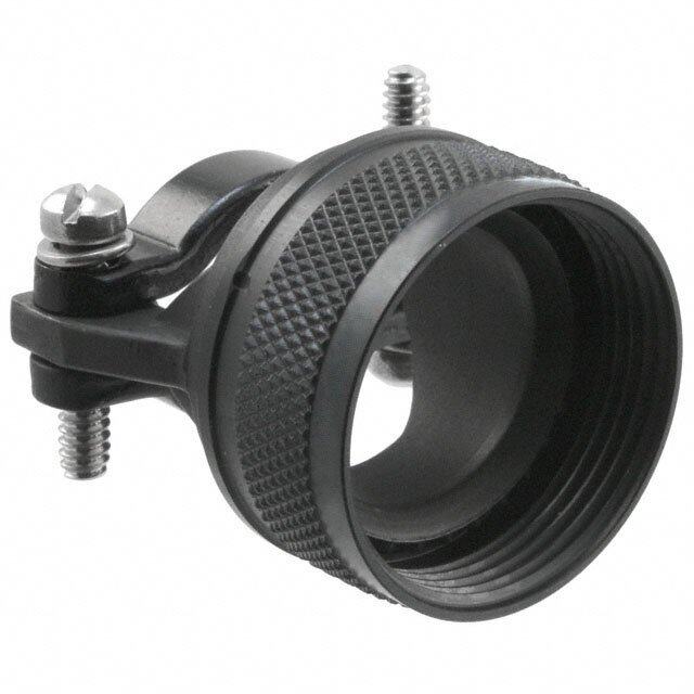
M85049 Backshells AS85049/38 Series - Cable clamp strain relief For connectors: • MIL-DTL-38999 Series III & IV • EN3645 Ordering information Basic Series M85049/38 S 11 N Self-locking option S: Self-locking, detented - utilizes an audible detented anti-decoupling device. N: Self-locking, non detented - utilizes an internal captivated anti-decoupling device (Self-Seating) with no audible clicking mechanism. - : Non self locking Shell size 9, 11, 13, 15, 16, 17, 19, 21, 23, 25 Material and plating A: Aluminum, black anodize N: Aluminum, electroless nickel S: Stainless steel, passivated W: Aluminum, olive drab cadmium over electroless nickel, 500 hours salt spray Dimensions C Cable entry A B D Knurl style B Max C Max Cable entry Cable entry Shell size A Thread Self-locking only Self-locking only D Max Min Max Class 2B inch mm inch mm inch mm inch mm inch mm 9 M12X1-6H 0.858 21.79 0.91 23.11 0.85 21.60 0.098 2.49 0.234 5.94 11 M15X1-6H 0.984 24.99 0.91 23.11 0.90 22.90 0.153 3.89 0.234 5.94 13 M18X1-6H 1.157 29.39 1.01 25.65 1.10 27.90 0.19 4.83 0.328 8.33 15 M22X1-6H 1.279 32.49 1.06 26.92 1.15 29.20 0.26 6.60 0.457 11.61 17 M25X1-6H 1.406 35.71 1.16 29.46 1.30 33.00 0.283 7.19 0.614 15.60 19 M28X1-6H 1.516 38.51 1.41 (35.81 1.50 38.10 0.325 8.26 0.634 16.10 21 M31X1-6H 1.642 41.71 1.51 38.35 1.60 40.60 0.343 8.71 0.698 17.73 23 M34X1-6H 1.768 44.91 1.66 42.16 1.70 43.20 0.381 9.68 0.823 20.90 25 M37X1-6H 1.889 47.98 1.76 44.70 1.80 45.70 0.418 10.62 0.853 21.67 Note: All dimensions are in inches and millimeters (inch/mm). For complete dimensions, see the applicable Military Specifi cation. Cable entry is defi ned as the envelope area of the cable or wire bundle. It is not intended for inspection criteria. 3
M85049 Backshells AS85049/43 Series - 45° cable clamp strain relief For connectors: MIL-DTL-5015 crimp MIL-DTL-26482 Series 2 AS81703 Series 3 MIL-DTL-83723 Series 1 & 3 Ordering information Basic Series M85049/43 - 10 N Self-locking option - : Non self locking Shell size 3, 8, 10, 12, 14, 16, 18, 20, 22, 24, 28, 32, 36, 40, 44, 48, 61 Material and plating N: Aluminum, electroless nickel W: Aluminum, olive drab cadmium over electroless nickel, 1000 hours salt spray Dimensions C C Max Cable entry Cable entry A Shell A Thread B Max closed D Max Min Max size Class 2B inch mm inch mm inch mm inch mm inch mm 3 0.562 - 24 UNEF 0.669 16.99 1.160 29.46 0.772 19.61 0.125 3.20 0.204 5.20 8 0.500 - 20 UNF 0.885 22.50 1.650 41.91 0.772 19.61 0.125 3.20 0.204 5.20 B 10 0.625 - 24 UNEF 1.010 25.70 1.694 43.03 0.803 20.40 0.187 4.70 0.286 7.30 12 0.750 - 20 UNEF 1.135 28.80 1.768 44.91 0.866 21.00 0.291 7.40 0.416 10.60 D 14 0.875 - 20 UNEF 1.260 32.00 1.840 46.74 0.928 23.57 0.351 8.90 0.476 12.10 Knurl style 16 1.000 - 20 UNEF 1.385 35.20 1.916 48.67 0.991 25.17 0.501 12.70 0.625 15.90 18 1.062 - 18 UNEF 1.570 39.88 2.034 51.66 1.110 28.19 0.518 13.20 0.706 17.90 20 1.188 - 18 UNEF 1.635 41.50 2.078 52.78 1.172 29.77 0.581 14.80 0.831 21.10 Cable entry 22 1.313 - 18 UNEF 1.760 44.70 2.122 53.90 1.235 31.37 0.644 16.40 0.956 24.30 24 1.438 - 18 UNEF 1.885 47.90 2.166 55.02 1.297 32.94 0.706 17.90 1.081 27.50 28 1.750 - 18 UNS 2.135 54.20 2.461 62.51 1.543 39.19 0.750 19.10 1.187 30.10 32 2.000 - 18 UNS 2.315 58.80 2.549 64.75 1.668 42.37 0.875 22.20 1.250 31.80 36 2.250 - 16 UN 2.635 66.90 2.595 65.91 1.793 45.54 0.938 23.80 1.375 34.90 40 2.500 - 16 UN 2.885 73.30 2.599 66.01 1.918 48.72 0.938 23.80 1.500 38.10 44 2.750 - 16 UN 3.135 79.60 2.860 72.64 2.132 54.15 1.188 30.20 1.750 44.50 48 3.000 - 16 UN 3.385 86.00 2.918 74.12 2.257 57.33 1.312 33.30 1.875 47.60 61 1.500 - 18 UNEF 1.653 41.99 1.676 42.57 1.204 30.58 0.706 17.90 1.081 27.50 Note: All dimensions are in inches and millimeters (inch/mm). For complete dimensions, see the applicable Military Specifi cation. Cable entry is defi ned as the envelope area of the cable or wire bundle. It is not intended for inspection criteria. 4
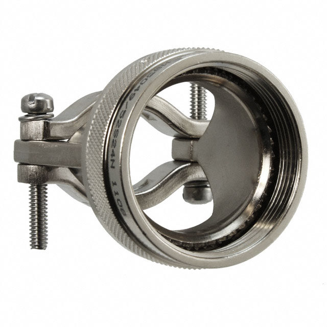
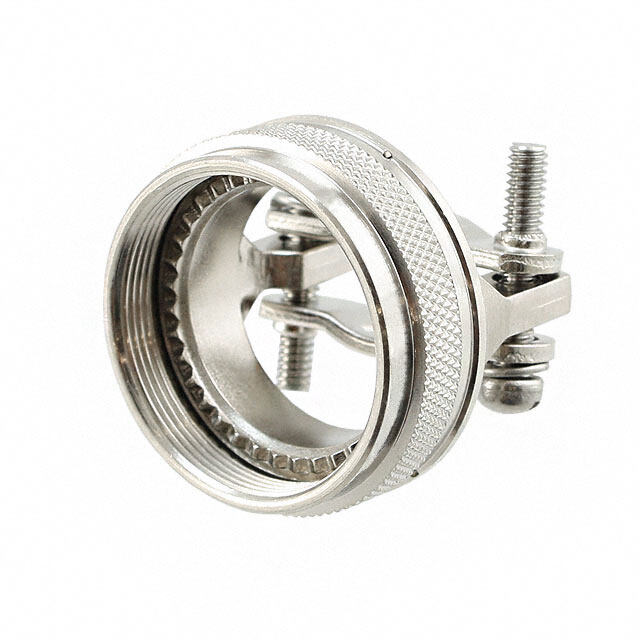
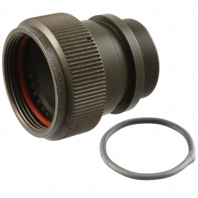
M85049 Backshells AS85049/49-2 Series - Cable clamp strain relief For connectors: MIL-DTL-27599 MIL-DTL-38999 Series I & II Ordering information Basic Series M85049/49-2 S 10 N Self-locking option S: Self-locking, detented - utilizes an audible detented anti-decoupling device. N: Self-locking, non detented - utilizes an internal captivated anti-decoupling device (Self-Seating) with no audible clicking mechanism. - : Non self locking Shell size 8, 10, 12, 14, 16, 18, 20, 22, 24 Material and plating A: Aluminum, black anodize N: Aluminum, electroless nickel S: Stainless steel, passivated W: Aluminum, olive drab cadmium over electroless nickel, 1000 hours salt spray Dimensions C Cable entry A B D Knurl style B Max C Max Cable entry Cable entry Shell A Thread Self-locking only Self-locking only D Max Min Max size Class 2B inch mm inch mm inch mm inch mm inch mm 8 0.438-28 UNEF 0.858 21.80 0.91 23.10 0.85 21.60 0.098 2.50 0.234 5.90 10 0.562-24 UNEF 0.984 25.00 0.91 23.10 0.90 22.90 0.153 3.90 0.234 5.90 12 0.688-24 UNEF 1.157 29.40 1.01 25.70 1.10 27.90 0.19 4.80 0.328 8.30 14 0.812-20 UNEF 1.279 32.50 1.06 26.90 1.15 29.20 0.26 6.60 0.457 11.60 16 0.938-20 UNEF 1.406 35.70 1.16 29.50 1.30 33.00 0.283 7.20 0.614 15.60 18 1.062-18 UNEF 1.516 38.50 1.41 35.80 1.50 38.10 0.325 8.30 0.634 16.10 20 1.188-18 UNEF 1.642 41.70 1.51 38.40 1.60 40.60 0.343 8.70 0.698 17.70 22 1.312-18 UNEF 1.768 44.90 1.66 42.20 1.70 43.20 0.381 9.70 0.823 20.90 24 1.438-18 UNEF 1.889 48.00 1.76 44.70 1.80 45.70 0.418 10.60 0.853 21.70 Note: All dimensions are in inches and millimeters (inch/mm). For complete dimensions, see the applicable Military Specifi cation. Cable entry is defi ned as the envelope area of the cable or wire bundle. It is not intended for inspection criteria. 5
M85049 Backshells AS85049/51 Series - 90° cable clamp strain relief For connectors: MIL-DTL-5015 crimp MIL-DTL-26482 Series 2 AS81703 Series 3 MIL-DTL-83723 Series 1 & 3 Ordering information Basic Series AS85049/51 S 10 N Self-locking option S: Self-locking, detented - utilizes an audible detented anti-decoupling device. N: Self-locking, non detented - utilizes an internal captivated anti-decoupling device (Self-Seating) with no audible clicking mechanism. -1: Non self locking Shell size 3, 8, 10, 12, 14, 16, 18, 20, 22, 24, 28, 32, 36, 40, 44, 48, 61 Material and plating A: Aluminum, black anodize N: Aluminum, electroless nickel W: Aluminum, olive drab cadmium over electroless nickel, 1000 hours salt spray Dimensions C A Shell A Thread Self-Blo cMkinagx only Self-Clo cMkinagx only D Max E ± 0.062 / 1.6 CabMle ienntry CabMlea exntry size Class 2B inch mm inch mm inch mm inch mm inch mm inch mm 3 0.562 - 24 UNEF Not available in self-locking 0.782 19.90 0.777 19.70 0.125 3.20 0.204 5.20 B 8 0.500 - 20 UNF 0.885 22.50 1.257 31.90 0.782 19.90 0.746 18.90 0.125 3.20 0.204 5.20 10 0.625 - 24 UNEF 1.010 25.70 1.339 34.00 0.862 21.90 0.805 20.40 0.187 4.70 0.286 7.30 12 0.750 - 20 UNEF 1.135 28.80 1.532 38.90 0.968 24.60 0.867 22.00 0.291 7.40 0.416 10.60 Knurl style 14 0.875 - 20 UNEF 1.26 32.00 1.592 40.40 1.003 25.50 0.930 23.60 0.351 8.90 0.476 12.10 16 1.000 - 20 UNEF 1.385 35.20 1.741 44.20 1.061 26.90 0.994 25.20 0.501 12.70 0.626 15.90 Cable entry 18 1.062 - 18 UNEF 1.510 38.40 1.853 47.10 1.394 35.40 1.171 29.70 0.518 13.20 0.706 17.90 20 1.188 - 18 UNEF 1.635 41.50 1.978 50.20 1.466 37.20 1.234 31.20 0.581 14.80 0.831 21.10 22 1.313 - 18 UNEF 1.760 44.70 2.108 53.50 1.572 39.90 1.296 32.90 0.644 16.40 0.956 24.30 24 1.438 - 18 UNEF 1.885 47.90 2.228 56.60 1.698 43.10 1.358 34.50 0.706 17.90 1.081 27.50 28 1.750 - 18 UNS 2.135 54.20 2.528 64.20 1.790 45.50 1.572 39.90 0.750 19.10 1.187 30.10 32 2.000 - 18 UNS 2.395 60.80 2.591 65.80 2.035 51.70 1.797 45.60 0.875 22.20 1.250 31.80 36 2.250 - 16 UN 2.635 66.90 2.716 69.00 2.386 60.60 1.922 48.80 0.938 23.80 1.375 34.90 E 40 2.500 - 16 UN 2.885 73.30 2.841 72.20 2.566 65.20 2.047 52.00 0.938 23.80 1.500 38.10 44 2.750 - 16 UN 3.135 79.60 3.091 78.50 2.86 72.60 2.296 58.30 1.188 30.20 1.750 44.50 48 3.000 - 16 UN 3.385 86.00 3.216 81.70 3.344 84.90 2.421 61.50 1.312 33.30 1.875 47.60 D 61 1.500 - 18 UNEF Not available in self-locking 1.775 45.10 1.388 35.30 0.706 17.90 1.081 27.50 Note: All dimensions are in inches and millimeters (inch/mm). For complete dimensions, see the applicable Military Specifi cation. Cable entry is defi ned as the envelope area of the cable or wire bundle. It is not intended for inspection criteria. 6
M85049 Backshells AS85049/52 Series - Straight cable clamp strain relief For connectors: MIL-DTL-5015 crimp MIL-DTL-26482 Series 2 AS81703 Series 3 MIL-DTL-83723 Series 1 & 3 Ordering information Basic Series AS85049/52 S 10 N Self-locking option S: Self-locking, detented - utilizes an audible detented anti-decoupling device. N: Self-locking, non detented - utilizes an internal captivated anti-decoupling device (Self-Seating) with no audible clicking mechanism. -1: Non self locking Shell size 3, 8, 10, 12, 14, 16, 18, 20, 22, 24, 28, 32, 36, 40, 44, 48, 61 Material and plating A: Aluminum, black anodize N: Aluminum, electroless nickel W: Aluminum, olive drab cadmium over electroless nickel, 1000 hours salt spray Dimensions C B Max C Max Cable entry Cable entry A Shell A Thread Self-locking only Self-locking only D Max Min Max size Class 2B inch mm inch mm inch mm inch mm inch mm 3 0.562 - 24 UNEF Not available in self-locking 0.782 19.90 0.125 3.20 0.204 5.20 B D 8 0.500 - 20 UNF 0.885 22.50 0.73 18.50 0.782 19.90 0.125 3.20 0.204 5.20 10 0.625 - 24 UNEF 1.010 25.70 0.85 21.60 0.862 21.90 0.187 4.70 0.286 7.30 12 0.750 - 20 UNEF 1.135 28.80 0.98 24.90 0.968 24.60 0.291 7.40 0.416 10.60 14 0.875 - 20 UNEF 1.26 32.00 0.98 24.90 1.003 25.50 0.351 8.90 0.476 12.10 Knurl style 16 1.000 - 20 UNEF 1.385 35.20 1.10 27.90 1.061 26.90 0.501 12.70 0.626 15.90 18 1.062 - 18 UNEF 1.510 38.40 1.35 34.30 1.394 35.40 0.518 13.20 0.706 17.90 Cable entry 20 1.188 - 18 UNEF 1.635 41.50 1.48 37.60 1.466 37.20 0.581 14.80 0.831 21.10 22 1.313 - 18 UNEF 1.760 44.70 1.60 40.60 1.572 39.90 0.644 16.40 0.956 24.30 24 1.438 - 18 UNEF 1.885 47.90 1.73 43.90 1.698 43.10 0.706 17.90 1.081 27.50 28 1.750 - 18 UNS 2.135 54.20 1.88 47.80 1.790 45.50 0.750 19.10 1.187 30.10 32 2.000 - 18 UNS 2.395 60.80 2.13 54.10 2.035 51.70 0.875 22.20 1.250 31.80 36 2.250 - 16 UN 2.635 66.90 2.44 62.00 2.386 60.60 0.938 23.80 1.375 34.90 40 2.500 - 16 UN 2.885 73.30 2.63 66.80 2.566 65.20 0.938 23.80 1.500 38.10 44 2.750 - 16 UN 3.135 79.60 3.00 76.20 2.86 72.60 1.188 30.20 1.750 44.50 48 3.000 - 16 UN 3.385 86.00 3.40 86.40 3.344 84.90 1.312 33.30 1.875 47.60 61 1.500 - 18 UNEF Not available in self-locking 1.775 45.10 0.706 17.90 1.081 27.50 Note: All dimensions are in inches and millimeters (inch/mm). For complete dimensions, see the applicable Military Specifi cation. Cable entry is defi ned as the envelope area of the cable or wire bundle. It is not intended for inspection criteria. 7
M85049 Backshells AS85049/53, 54, 55 Series - One arm strain relief For connectors: MIL-DTL-5015 crimp MIL-DTL-26482 Series 2 AS81703 Series 3 MIL-DTL-83723 Series 1 & 3 Ordering information Basic Series AS85049/ 53 - 10 N Angle 53: Straight 54: 45° 55: 90° Self-locking option - : Non self locking Shell size 3, 8, 10, 12, 14, 16, 18, 20, 22, 24, 28 Material and plating A: Aluminum, black anodize N: Aluminum, electroless nickel W: Aluminum, olive drab cadmium over electroless nickel, 1000 hours salt spray Dimensions C D E A Cable For new design use: B entry M85049/43 (45°), M85049/51 (90°) and F M85049/52 (straight) Knurl style Cable entry Cable entry Shell A Thread B Max C Max D Max E Max F Max Cable entry size Class 2B inch mm inch mm inch mm inch mm inch mm inch mm 3 0.562 - 24 UNEF 0.780 19.80 0.260 6.60 8 0.500 - 20 UNF 0.660 16.80 1.290 32.80 0.260 6.60 0.954 24.00 10 0.625 - 24 UNEF 0.780 19.80 0.365 9.30 12 0.750 - 20 UNEF 0.940 23.90 1.232 31.30 0.730 18.50 1.620 41.10 0.501 12.70 14 0.875 - 20 UNEF 1.050 26.70 1.660 42.20 0.575 14.60 16 1.000 - 20 UNEF 1.240 31.50 1.204 30.60 0.700 17.80 1.720 43.70 18 1.062 - 18 UNEF 1.380 35.10 0.779 19.80 20 1.188 - 18 UNEF 1.500 38.10 1.310 33.30 1.790 45.50 0.904 23.00 22 1.313 - 18 UNEF 1.630 41.40 1.430 36.30 1.482 37.60 1.850 47.00 1.029 26.10 0.750 19.10 24 1.438 - 18 UNEF 1.750 44.50 1.560 39.60 1.910 48.50 1.144 29.10 28 1.750 - 18 UNS 1.970 50.00 1.560 39.60 1.469 37.30 2.060 52.30 1.379 35.00 Note: All dimensions are in inches and millimeters (inch/mm). For complete dimensions, see the applicable Military Specifi cation. Cable entry is defi ned as the envelope area of the cable or wire bundle. It is not intended for inspection criteria. 8
M85049 Backshells AS85049/60-1 Series - Shrink boot adapter For connectors: MIL-DTL-5015 crimp MIL-DTL-26482 Series 2 AS81703 Series 3 MIL-DTL-83723 Series 1 & 3 Ordering information Basic Series M85049/60-1 N 10 Material and plating A: Aluminum, black anodize N: Aluminum, electroless nickel W: Aluminum, olive drab cadmium over electroless nickel, 1000 hours salt spray Shell size 3, 8, 10, 12, 14, 16, 18, 20, 22, 24, 28, 32, 36, 40, 44, 48, 61 Dimensions C A Cable B D entry Knurl style Shell A Thread B Max C Max D Max Cable entry size Class 2B inch mm inch mm inch mm inch mm 3 0.562 - 24 UNEF 0.670 17.00 0.533 13.50 0.250 6.40 8 0.500 - 20 UNF 0.620 15.70 0.533 13.50 0.250 6.40 10 0.625 - 24 UNEF 0.740 18.80 0.605 15.40 0.355 9.00 12 0.750 - 20 UNEF 0.860 21.80 0.774 19.70 0.491 12.50 14 0.875 - 20 UNEF 0.980 24.90 0.838 21.30 0.565 14.40 0.832 21.10 16 1.000 - 20 UNEF 1.110 28.20 0.963 24.50 0.690 17.50 18 1.062 - 18 UNEF 1.220 31.00 1.042 26.50 0.769 19.50 20 1.188 - 18 UNEF 1.350 34.30 1.217 30.90 0.894 22.70 22 1.313 - 18 UNEF 1.470 37.30 1.355 34.40 1.019 25.90 24 1.438 - 18 UNEF 1.590 40.40 1.443 36.70 1.134 28.80 28 1.750 - 18 UNS 1.970 50.00 1.709 43.40 1.369 34.80 32 2.000 - 18 UNS 2.220 56.40 1.919 48.70 1.615 41.00 36 2.250 - 16 UN 2.470 62.70 2.169 55.10 1.830 46.50 0.994 25.30 40 2.500 - 16 UN 2.720 69.10 2.402 61.00 2.045 51.90 44 2.750 - 16 UN 2.970 75.40 2.657 67.50 2.300 58.40 48 3.000 - 16 UN 3.220 81.80 2.907 73.80 2.550 64.80 61 1.500 - 18 UNEF 1.650 41.90 0.832 21.10 1.529 38.80 1.174 29.80 Note: All dimensions are in inches and millimeters (inch/mm). For complete dimensions, see the applicable Military Specifi cation. Cable entry is defi ned as the envelope area of the cable or wire bundle. It is not intended for inspection criteria. 9
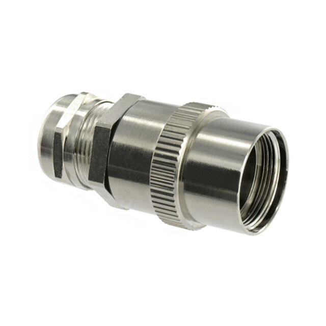
M85049 Backshells AS85049/62 Series - Shrink boot adapter For connectors: MIL-DTL-27599 MIL-DTL-38999 Series I & II Ordering information Basic Series M85049/62 10 N D Shell size 8, 10, 12, 14, 16, 18, 20, 22, 24 Material and plating A: Aluminum, black anodize N: Aluminum, electroless nickel S: Stainless steel, passivated W: Aluminum, olive drab cadmium over electroless nickel, 1000 hours salt spray Drain hole D: with drain hole empty: without drain hole Dimensions C A Cable B D entry Knurl style Shell A Thread B Max C Max D Max Cable entry size Class 2B inch mm inch mm inch mm inch mm 8 0.438 - 28 UNEF 0.750 19.10 0.533 13.50 0.250 6.40 10 0.562 - 24 UNEF 0.850 21.60 0.605 15.40 0.375 9.50 12 0.688 - 24 UNEF 1.000 25.40 0.774 19.70 0.500 12.70 14 0.813 - 20 UNEF 1.100 27.90 0.838 21.30 0.625 15.90 16 0.938 - 20 UNEF 1.250 31.80 1.000 25.40 0.963 24.50 0.750 19.10 18 1.063 - 18 UNEF 1.400 35.60 1.042 26.50 0.812 20.60 20 1.188 - 18 UNEF 1.500 38.10 1.217 30.90 0.937 23.80 22 1.313 - 18 UNEF 1.650 41.90 1.355 34.40 1.062 27.00 24 1.438 - 18 UNEF 1.750 44.50 1.443 36.70 1.188 30.20 Note: All dimensions are in inches and millimeters (inch/mm). For complete dimensions, see the applicable Military Specifi cation. Cable entry is defi ned as the envelope area of the cable or wire bundle. It is not intended for inspection criteria. 10
M85049 Backshells AS85049/69 Series - Shrink boot adapter For connectors: MIL-DTL-38999 Series III & IV EN3645 Ordering information Basic Series M85049/69 11 N Shell size 9, 11, 13, 15, 17, 19, 21, 23, 25 Material and plating A: Aluminum, black anodize N: Aluminum, electroless nickel S: Stainless steel, passivated W: Aluminum, olive drab cadmium over electroless nickel, 1000 hours salt spray Drain hole D: with drain hole empty: without drain hole Dimensions C A Cable B D entry Knurl style Shell A Thread B Max C Max D Max Cable entry size Class 2B inch mm inch mm inch mm inch mm 9 M12 X 1 - 6H 0.750 19.10 0.533 13.50 0.250 6.40 11 M15 X 1 - 6H 0.850 21.60 0.605 15.40 0.375 9.50 13 M18 X 1 - 6H 1.000 25.40 0.774 19.70 0.500 12.70 15 M22 X 1 - 6H 1.150 29.20 0.838 21.30 0.625 15.90 17 M25 X 1 - 6H 1.250 31.80 0.710 18.00 0.963 24.50 0.750 19.10 19 M28 X 1 - 6H 1.400 35.60 1.042 26.50 0.812 20.60 21 M31 X 1 - 6H 1.500 38.10 1.217 30.90 0.938 23.80 23 M34 X 1 - 6H 1.650 41.90 1.355 34.40 1.062 27.00 25 M37 X 1 - 6H 1.785 47.00 1.443 36.70 1.188 30.20 Note: All dimensions are in inches and millimeters (inch/mm). For complete dimensions, see the applicable Military Specifi cation. Cable entry is defi ned as the envelope area of the cable or wire bundle. It is not intended for inspection criteria. 11
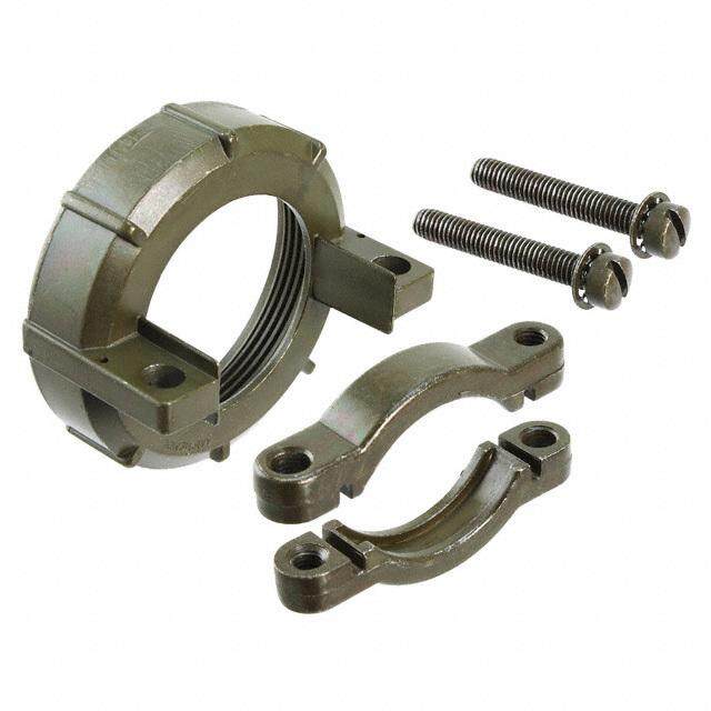
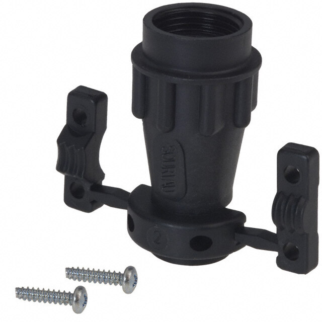
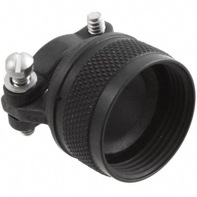
M85049 Backshells AS85049/82, 83, 84 Series - Banding backshell with self-locking For connectors: MIL-DTL-5015 crimp MIL-DTL-26482 Series 2 AS81703 Series 3 MIL-DTL-83723 Series 1 & 3 Ordering information Basic Series AS85049/ 82 - 10 N 02 Angle 82: Straight 83: 45° 84: 90° (size 28 not qualifi ed for AS85049/84) Self-locking option - : Detended N: Non detended Shell size: 8, 10, 12, 14, 16, 18, 20, 22, 24, 28 (size 28 not qualifi ed for AS85049/84) Material and plating N: Aluminum, electroless nickel P: Aluminum, olive drab cadmium over electroless nickel with polysulfi de sealant strips W: Aluminum, olive drab cadmium over electroless nickel, 1000 hours salt spray Entry size (see table below): 02, 03 Dimensions 1.35 / 34.30 Max C E A D Polysulfi te B Cable stripes CS entry fi nish option 0.14-0.13 / F 3.50-3.30 Cable entry 0.73 / 18.50 Termination area Cable free of cadmium entry Cable entry Cable entry Shell A Thread B Max C Max D Max E Max F Max Size 02 ±0.01/0.30 Size 03 ±0.01/0.30 size Class 2B inch mm inch mm inch mm inch mm inch mm inch mm inch mm 8 0.500 - 20 UNF 0.886 22.40 0.870 22.10 1.160 29.50 1.188 30.20 1.417 36.00 N/A N/A 0.250 6.40 10 0.625 - 24 UNEF 1.010 25.70 0.890 22.60 1.180 30.00 1.281 32.50 1.480 37.60 N/A N/A 0.312 7.90 12 0.750 - 20 UNEF 1.130 28.70 0.920 23.40 1.200 30.50 1.406 35.70 1.542 39.20 0.312 7.90 0.438 11.10 14 0.875 - 20 UNEF 1.260 32.00 0.940 23.90 1.220 31.00 1.531 38.90 1.605 40.80 0.438 11.10 0.562 14.30 16 1.000 - 20 UNEF 1.386 35.10 0.960 24.40 1.250 31.80 1.656 42.10 1.667 42.30 0.500 12.70 0.625 15.90 18 1.062 - 18 UNEF 1.510 38.40 0.980 24.90 1.260 32.00 1.718 43.60 1.730 43.90 0.625 15.90 0.750 19.10 20 1.188 - 18 UNEF 1.636 41.40 1.000 25.40 1.290 32.80 1.844 46.80 1.792 45.50 0.625 15.90 0.812 20.60 22 1.313 - 18 UNEF 1.760 44.70 1.030 26.20 1.310 33.30 1.938 49.20 1.850 47.00 0.688 17.50 0.938 23.80 24 1.438 - 18 UNEF 1.886 47.80 1.050 26.70 1.340 34.00 2.093 53.20 1.917 48.70 0.750 19.10 1.000 25.40 28 1.750 - 18 UNS 2.136 54.10 1.100 27.90 1.380 35.10 2.531 64.30 2.042 51.90 0.875 22.20 1.125 28.60 Note: All dimensions are in inches and millimeters (inch/mm). For complete dimensions, see the applicable Military Specifi cation. Cable entry is defi ned as the envelope area of the cable or wire bundle. It is not intended for inspection criteria. 12
M85049 Backshells AS85049/85, 86, 87 Series - Banding backshell with self-locking For connectors: MIL-DTL-27599 MIL-DTL-38999 Series I & II Ordering information Basic Series AS85049/ 85 - 10 N 02 Angle 85: Straight 86: 45° 87: 90° Self-locking option - : Detended N: Non detended Shell size: 8, 10, 12, 14, 16, 18, 20, 22, 24 Material and plating N: Aluminum, electroless nickel P: Aluminum, olive drab cadmium over electroless nickel with polysulfi de sealant strips W: Aluminum, olive drab cadmium over electroless nickel, 1000 hours salt spray Entry size (see table below): 02, 03 Dimensions 1.35 / 34.30 Max C E A D Polysulfi te B Cable stripes CS entry fi nish option 0.14-0.13 / F 3.50-3.30 Cable entry 0.73 / 18.50 Termination area Cable free of cadmium entry Cable entry for AS85049/85, Cable entry for AS85049/86 Shell A Thread B Max C Max D Max E Max F Max Straight version and AS85049/87, 45° & 90° size Class 2B Size 01 Size 02 Size 02 Size 03 inch mm inch mm inch mm inch mm inch mm inch mm inch mm inch mm inch mm 8 0.438-28 UNEF 0.860 21.80 0.870 22.10 1.160 29.50 1.375 34.90 1.417 36.00 N/A N/A 0.250 6.40 N/A N/A 0.250 6.40 10 0.562-24 UNEF 0.990 25.10 0.900 22.90 1.190 30.20 1.437 36.50 1.480 37.60 N/A N/A 0.312 7.90 N/A N/A 0.312 7.90 12 0.688-24 UNEF 1.160 29.50 0.920 23.40 1.210 30.70 1.562 39.70 1.553 39.40 0.312 7.90 0.438 11.10 0.312 7.90 0.438 11.10 14 0.812-20 UNEF 1.280 32.50 0.950 24.10 1.240 31.50 1.687 42.80 1.614 41.00 0.438 11.10 0.562 14.30 0.438 11.10 0.562 14.30 16 0.938-20 UNEF 1.410 35.80 0.980 24.90 1.260 32.00 1.750 44.50 1.678 42.60 0.500 12.70 0.625 15.90 0.500 12.70 0.625 15.90 18 1.062-18 UNEF 1.520 38.60 0.980 24.90 1.270 32.30 1.875 47.60 1.733 44.00 0.625 15.90 0.750 19.10 0.625 15.90 0.750 19.10 20 1.188-18 UNEF 1.640 41.70 1.010 25.70 1.300 33.00 1.938 49.20 1.796 45.60 0.625 15.90 0.812 20.60 0.625 15.90 0.812 20.60 22 1.312-18 UNEF 1.770 45.00 1.040 26.40 1.330 33.80 2.062 52.40 1.859 47.20 0.688 17.50 0.938 23.80 0.688 17.50 0.938 23.80 24 1.438-18 UNEF 1.890 48.00 1.070 27.20 1.350 34.30 2.125 54.00 1.919 48.70 0.750 19.10 1.000 25.40 0.750 19.10 1.000 25.40 Note: All dimensions are in inches and millimeters (inch/mm). For complete dimensions, see the applicable Military Specifi cation. Cable entry is defi ned as the envelope area of the cable or wire bundle. It is not intended for inspection criteria. 13
M85049 Backshells AS85049/88, 89, 90 Series - Banding backshell with self-locking For connectors: MIL-DTL-38999 Series III & IV EN3645 Ordering information Basic Series AS85049/ 88 - 11 N 02 Angle 88: Straight 89: 45° 90: 90° Self-locking option - : Detended N: Non detended Shell size: 9, 11, 13, 15, 17, 19, 21, 23, 25 Material and plating N: Aluminum, electroless nickel P: Aluminum, olive drab cadmium over electroless nickel with polysulfi de sealant strips W: Aluminum, olive drab cadmium over electroless nickel, 1000 hours salt spray Entry size (see table below): 02, 03 Dimensions 1.35 / 34.30 Max C E A D Polysulfi te B Cable stripes CS entry fi nish option 0.14-0.13 / F 3.50-3.30 Cable entry 0.73 / 18.50 Termination area Cable free of cadmium entry Cable entry Cable entry Shell A Thread B Max C Max D Max E Max F Max Size 02 Size 03 size Class 2B inch mm inch mm inch mm inch mm inch mm inch mm inch mm 9 M12X1-6H 0.860 21.80 1.010 25.70 1.160 29.50 1.375 34.90 1.417 36.00 N/A N/A 0.250 6.40 11 M15X1-6H 0.990 25.10 1.030 26.20 1.190 30.20 1.437 36.50 1.480 37.60 N/A N/A 0.312 7.90 13 M18X1-6H 1.160 29.50 1.060 26.90 1.210 30.70 1.562 39.70 1.553 39.40 0.312 7.90 0.438 11.10 15 M22X1-6H 1.280 32.50 1.080 27.40 1.240 31.50 1.687 42.80 1.614 41.00 0.438 11.10 0.562 14.30 17 M25X1-6H 1.410 35.80 1.110 28.20 1.260 32.00 1.750 44.50 1.678 42.60 0.500 12.70 0.625 15.90 19 M28X1-6H 1.520 38.60 1.120 28.40 1.270 32.30 1.875 47.60 1.733 44.00 0.625 15.90 0.750 19.10 21 M31X1-6H 1.640 41.70 1.150 29.20 1.300 33.00 1.938 49.20 1.796 45.60 0.625 15.90 0.812 20.60 23 M34X1-6H 1.770 45.00 1.170 29.70 1.330 33.80 2.062 52.40 1.859 47.20 0.688 17.50 0.938 23.80 25 M37X1-6H 1.890 48.00 1.200 30.50 1.350 34.30 2.125 54.00 1.919 48.70 0.750 19.10 1.000 25.40 Note: All dimensions are in inches and millimeters (inch/mm). For complete dimensions, see the applicable Military Specifi cation. Cable entry is defi ned as the envelope area of the cable or wire bundle. It is not intended for inspection criteria. 14
M85049 Backshells M85049/93 Series - Shield support ring For ALL connectors. Ordering information Basic Series M85049/93 10 Dash number 4, 6, 8, 10, 12, 14, 16, 18, 20, 22, 24, 26, 28 Dimensions Dash X Y Z number inch mm inch mm inch mm 0.88 / 22.35 Max 4 0.25 6.40 0.404 10.30 0.36 9.10 6 0.38 9.70 0.529 13.40 0.49 12.40 Z 8 0.50 12.70 0.654 16.60 0.61 15.50 10 0.63 16.00 0.779 19.80 0.74 18.80 12 0.75 19.10 0.904 23.00 0.86 21.80 Y X 14 0.88 22.40 1.029 26.10 0.99 25.10 16 1.00 25.40 1.154 29.30 1.11 28.20 18 1.13 28.70 1.279 32.50 1.24 31.50 20 1.25 21.80 1.404 35.70 1.36 34.50 22 1.38 35.10 1.529 38.90 1.49 37.80 0.55-0.05 / 13.97-1.27 24 1.50 38.10 1.654 42.00 1.61 40.90 26 1.63 41.40 1.779 45.20 1.74 44.20 28 1.75 44.50 1.904 48.60 1.86 47.20 Note: All dimensions are in inches and millimeters (inch/mm). For complete dimensions, see the applicable Military Specifi cation. 15
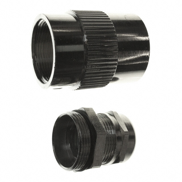
Protective Caps MS27501/MS27502 Series - Protective caps for plug and receptacle For connectors: MIL-DTL-38999 Series I Ordering information Basic Series MS27 501 B 11 N Cap type 501: Cap for plug 502: Cap for receptacle Material and plating B: Aluminum, olive drab cadmium, 500 hours salt spray C: Aluminum, black anodize F: Aluminum, electroless nickel Shell size: 9, 11, 13, 15, 17, 19, 21, 23, 25 Style A: Without chain C: Chain with eyelet N: Chain with ring (MS27502 only) Chain length (in inches/mm) empty: Standard chain length, see table below (C Max) L: 5.0/127.0 M: 6.0/152.4 (MS27501 only) N: 7.0/177.8 (MS27501 only) Dimensions Cap for plug Type 501 Cap for receptacle Type 502 0.90 / 22.9 Max 0.82 / 20.8 Max Ø 0.167 / 4.24 Ø 0.167 / 4.24 ØD A B Ø Ø Bent ring for receptacle cap C Max C Max 20° +05°° ØA Max ØB Max C Max ØD Min Size inch mm inch mm inch mm inch mm 9 0.82 20.80 0.82 20.80 0.70 17.80 3.00 76.20 11 0.94 23.90 0.94 23.90 0.84 21.30 13 1.07 27.20 1.10 27.90 1.01 25.70 15 1.19 30.20 1.22 31.00 1.14 29.00 3.50 88.90 17 1.35 33.50 1.34 34.00 1.26 32.00 19 1.44 36.60 1.46 37.10 1.39 35.30 21 1.57 39.90 1.58 40.10 1.51 38.40 23 1.69 42.90 1.70 43.20 4.00 101.60 1.64 41.70 25 1.82 46.20 1.83 46.50 1.76 44.70 Note: All dimensions are in inches and millimeters (inch/mm). 16
Protective Caps D38999 Series - Protective caps for plug and receptacle For connectors: MIL-DTL-38999 Series III Ordering information Basic Series D38999/ 32 W 11 N writing. Cap type d in 3323:: CCaapp ffoorr prelucegp tacle pprove M Wat:e rAialul manindu mpl,a otilnivge drab cadmium d, unless a F: Aluminum, nickel bite Z: Aluminum, black zinc nickel prohi SShtyellel size: 9, 11, 13, 15, 17, 19, 21, 23, 25 duplication is N: With stainless steel rope and ring Any R: With stainless steel rope and eyelet ment. blic announce pu Cap for plug Type 32 ØD+0.2 DimCaepn fosri roecnesptacle Type 33 prior notifi cation or 0.98 / 25.00 Max Ø 0.167 / 4.24 -0 Thread S2B 0.79 / 20.00 Max Ø 0.167 / 4.24ØE+-00.2 U for changes without A URI ØAThread 2A S1111i9z1357e 01111i.....n80124c81893Øh96197A MCa22333 mMx25036.....ma68005x00000 01111i.....n80124c94854Øh83129B Ma22333mx26016.....m8508800000 33in..39ch10C Ma89xm49ØB..m0000 00001i.....n57990c92114h14333ØD11222m58336.....m0422500000 C 00111Mi.....n79012ac21498xh43333ØE12233m83602.....m4253600000 2T00011hA.....67801r/25708e250507aB00005d -----m:00000 S.....o11111tduPPPPPib-----fi00000 erA.....eB33333dceCLLLLLe np-----6MtTTTTTt 0raiSSSSSEcn°lge 2 fco0a°rp +05°° U Sept 2015 - SOURIAU is a registered trademark.particulars and shall not form part of any contract. All rights reserved to SO 1291 11..564733 3492..2500 11..562486 3481..8800 11..129833 3302..3600 11..453477 3369..5300 11..23570500--00..11PP--00..33LL--TTSS OURIAgeneral 2235 11..890235 4458..8900 11..796241 4448..8800 4.49 114.00 11..453477 3369..5300 11..678792 4425..9000 11..56020500--00..11PP--00..33LL--TTSS Copyright Spresents only 1 © ment Note: All dimensions are in inches aFndo mril lifmuetretrsh (inechr/m iomn)r.f ovrismita otiuorn w ceobn tsaitcet uwsw awt .ssuunnbbaannkk.csoarlpes.c@oemsterline.com WPNM85049WUSEN0All information in this docu 17
Mouser Electronics Authorized Distributor Click to View Pricing, Inventory, Delivery & Lifecycle Information: S unbank: M85049/38S25N M85049/88-15W02 D38999/33W11R M85049/38-21W D38999/33W15N M85049/1925W09 M85049/88-11N03 M85049/38S19W M85049/1913N03 M85049/88-19W03 D38999/33W19N D38999/33W21N M85049/1917N03 M85049/88-25N03 D38999/32W23R M85049/39S13W M85049/1919W07 M85049/38-21N M85049/1925N06 M85049/39S15W M85049/38S21N D38999/33W9R M85049/88-15N03 D38999/33W21R M85049/39S11W D38999/32W17N M85049/88-17N03 M85049/88-9W03 M85049/1921W05 M85049/39-9N M85049/1917W06 M85049/88-15W03 D38999/32W19N M85049/38-25N M85049/39S15N M85049/39S25W D38999/32W15R M85049/88-25W02 D38999/32W25R M85049/38S23N M85049/38S23W M85049/1913W02 M85049/88-17N02 M85049/1913W04 M85049/1915W05 M85049/1917W04 M85049/38-15W D38999/33W13N M85049/39-17W D38999/32W13N D38999/32W15N M85049/38-11N M85049/88-17W03 D38999/32W21N M85049/39S9N M85049/1911W03 M85049/88-17W02 M85049/88-23W03 D38999/33W17R M85049/38-13N M85049/88-19W02 D38999/33W23R M85049/38-25W D38999/32W17R M85049/39-13W M85049/38-15A M85049/39-15N M85049/39S17W D38999/33W17N M85049/38S17W D38999/32W9R M85049/88-13W02 M85049/91-17M D38999/32W11R M85049/38-23N M85049/39S13N M85049/38S9W D38999/32W19R M85049/1915W04 M85049/38-11W M85049/38-13A M85049/39-11N M85049/1915W03 M85049/1925W05 M85049/38-23W D38999/32W25N M85049/88-9N03 D38999/33W13R M85049/1917N04 M85049/39-19W M85049/88-25W03 M85049/38S15S M85049/39-25W M85049/88-13W03 M85049/38-17W M85049/1911W02 M85049/1913N04 M85049/1915N03 M85049/39S9W M85049/38-19W