ICGOO在线商城 > M2015BB1W01
 Datasheet下载
- 型号: M2015BB1W01
- 制造商: NKK Switches
- 库位|库存: xxxx|xxxx
- 要求:
| 数量阶梯 | 香港交货 | 国内含税 |
| +xxxx | $xxxx | ¥xxxx |
查看当月历史价格
查看今年历史价格
M2015BB1W01产品简介:
ICGOO电子元器件商城为您提供M2015BB1W01由NKK Switches设计生产,在icgoo商城现货销售,并且可以通过原厂、代理商等渠道进行代购。 提供M2015BB1W01价格参考以及NKK SwitchesM2015BB1W01封装/规格参数等产品信息。 你可以下载M2015BB1W01参考资料、Datasheet数据手册功能说明书, 资料中有M2015BB1W01详细功能的应用电路图电压和使用方法及教程。
| 参数 | 数值 |
| 3D型号 | http://www.nkkswitches.com/model.aspx?part=M2015BB1W01&vendor=digikey |
| 产品目录 | |
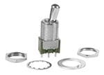
| 描述 | SWITCH TOGGLE SPDT 6A 125V |
| 产品分类 | |
| 品牌 | NKK Switches |
| 数据手册 | |
| 产品图片 |
|
| 产品型号 | M2015BB1W01 |
| PCN设计/规格 | |
| rohs | 无铅 / 符合限制有害物质指令(RoHS)规范要求 |
| RoHS指令信息 | |
| 产品系列 | M |
| 产品培训模块 | http://www.digikey.cn/PTM/IndividualPTM.page?site=cn&lang=zhs&ptm=7079http://www.digikey.cn/PTM/IndividualPTM.page?site=cn&lang=zhs&ptm=30248 |
| 侵入防护 | - |
| 其它名称 | M2015BB1W01-RO |
| 包装 | 散装 |
| 安装类型 | 面板安装 |
| 工作温度 | -30°C ~ 85°C |
| 开关功能 | 开-瞬时 |
| 标准包装 | 1 |
| 照明 | 不发光 |
| 照明电压(标称值) | - |
| 照明类型,颜色 | - |
| 特性 | 环氧树脂密封端子 |
| 特色产品 | http://www.digikey.com/cn/zh/ph/NKK/M_Series.html |
| 电气寿命 | 25,000 次循环 |
| 电路 | SPDT |
| 相关产品 | /product-detail/zh/AT402S/360-2982-ND/1045998 |
| 端子类型 | 焊片 |
| 致动器材料 | 黄铜,镀铬 |
| 致动器类型 | 标准圆形 |
| 致动器长度 | 11.50mm |
| 衬套螺纹 | M12 x 1 |
| 面板开口尺寸 | 圆形 - 12.50mm 直径 |
| 额定电压-AC | 125V |
| 额定电压-DC | 30V |
| 额定电流 | 6A(AC),3A(DC) |


- 商务部:美国ITC正式对集成电路等产品启动337调查
- 曝三星4nm工艺存在良率问题 高通将骁龙8 Gen1或转产台积电
- 太阳诱电将投资9.5亿元在常州建新厂生产MLCC 预计2023年完工
- 英特尔发布欧洲新工厂建设计划 深化IDM 2.0 战略
- 台积电先进制程称霸业界 有大客户加持明年业绩稳了
- 达到5530亿美元!SIA预计今年全球半导体销售额将创下新高
- 英特尔拟将自动驾驶子公司Mobileye上市 估值或超500亿美元
- 三星加码芯片和SET,合并消费电子和移动部门,撤换高东真等 CEO
- 三星电子宣布重大人事变动 还合并消费电子和移动部门
- 海关总署:前11个月进口集成电路产品价值2.52万亿元 增长14.8%


PDF Datasheet 数据手册内容提取
Series M Miniature Toggles s e glA General Specifications g o T s er Electrical Capacity (Resistive Load) k c o Power Level (silver): 6A @ 125V AC & 3A @ 250V AC R 4A @ 30V DC for On-None-On & On-None-Off; 3A @ 30V DC for all other circuits s Logic Level (gold): 0.4VA maximum @ 28V AC/DC maximum (Applicable Range 0.1mA ~ 0.1A @ 20mV ~ 28V) n o Logic/Power Level (gold over silver): Combines silver & gold ratings utt b Note: Find additional explanation of dual rating & operating range in Supplement section. h s u P Other Ratings PB Contact Resistance: 10 milliohms maximum for silver; 20 milliohms maximum for gold ed Insulation Resistance: 1,000 megohms minimum @ 500V DC at n Dielectric Strength: 1,000V AC minimum between contacts for 1 minute minimum; mi u 1,500V AC minimum between contacts and case for 1 minute minimum Ill Mechanical Life: 100,000 operations minimum; 50,000 operations minimum for flat, locking & splashproof devices e abl Electrical Life: 25,000 operations minimum for silver; 50,000 operations minimum for gold; m m 50,000 operations minimum for silver at 3A @ 125V AC a gr Angle of Throw: 25° o Pr Materials & Finishes s Toggle: Brass with chrome plating Frame: Stainless steel k c o Bushing: Brass with nickel plating Support Bracket: Brass with tin plating yl Ke Case: Diallyl phthalate resin (UL94V–0) Movable Contactor: Phosphor bronze with silver or gold plating Movable Contacts: Silver alloy (code W); copper with gold plating (code G); or silver alloy with gold plating (code A) s arie Stationary Contacts: Silver with silver plating (code W); copper or brass with gold plating (code G); ot or silver with gold plating (code A) R Terminals: Copper or brass with silver plating; or copper or brass with gold plating Environmental Data es Operating Temp Range: –30°C through +85°C (–22°F through +185°F) d Sli Humidity: 90 ~ 95% humidity for 96 hours @ 40°C (104°F) Vibration: 10 ~ 55Hz with peak-to-peak amplitude of 1.5mm traversing the frequency range & returning in 1 minute; 3 right angled directions for 2 hours s Shock: 50G (490m/s2) acceleration (tested in 6 right angled directions, with 5 shocks in each direction) e ctil Sealing: Splashproof bushing options B3, D3, D8, L3, & L8, which have o-rings inside & outside the a T bushing, meet IP67 of IEC60529 Standards. Installation Tilt Mounting Torque: 31..05NNmm ((2163. 5lb5• ilnb)• dino)u dboleu bnluet n&u t0 f.o7rN lamr g(6e blbu•sihni)n sgi;n gle nut for all other bushings Processing Soldering: Wave Soldering (PC version) for Gold: See Profile A in Supplement section. h Manual Soldering for Gold: See Profile A in Supplement section. c ou Wave Soldering (PC version) for Silver: See Profile B in Supplement section. T Manual Soldering for Silver: See Profile B in Supplement section. Note: Lever must be in OFF (center) position while soldering. ors Cleaning: These devices are not process sealed. Hand clean locally using alcohol based solution. at c Standards & Certifications di In Flammability Standards: UL94V–0 for case UL: File No. E44145 - Recognized only when ordered with marking on switch. s orie Add “/U” or “/CUL” before dash in part number to order UL recognized switch. s All models recognized at 6A @ 125V AC, 3A @ 250V AC or 0.4VA maximum @ 28V DC maximum. s e cc CSA: File No. 023535_0_000 - Certified only when ordered with marking on switch. A Add “/C” before dash in part number to order CSA certified switch. nt All models certified at 6A @ 125V AC or 3A @ 250V AC or 0.4VA maximum @ 28V maximum. e m e pl p u S A52 www.nkkswitches.com 5/9/18
Series M Miniature Toggles s e Distinctive Characteristics A gl g o T s Antirotation design, standard on noncylindrical levers, mates toggle er k c and bushing; bottom of toggle has two flatted sides which fit into Ro a complementary opening inside bushing. ns o Antijamming design protects contacts from damage due utt b h to excessive downward force on actuator. s u P B P High torque bushing construction prevents rotation d e or separation from frame during installation. at n mi u High insulating barriers increase isolation of Ill e bl circuits in multipole devices and provide a m m added protection to contact points. a gr o Pr Molded diallyl phthalate case has a UL flammability rating of 94V-0. ks c o yl e K Epoxy sealed terminals prevent entry of solder flux and other contaminants. s e ari Prominent external insulating barriers ot R increase insulation resistance and dielectric strength. s e d Interlocked actuator block, lever, and interior guide Sli prevent switch failure due to biased lever movement. s e Clinching of frame to case well above base and terminals ctil provides 1,500V dielectric strength. Ta Tilt Actual Size h c u o T Bushing Mount Page A52 s or at c di n I Bracket PC Mount Page A64 s e ori s s e c c A nt Angle PC Mount Page A70 e m e pl p u S www.nkkswitches.com A53
Series M Bushing Mount Miniature Toggles s e glA TYPICAL SWITCH ORDERING EXAMPLE g o T s M20 1 3 S S1 er k c o R s n o utt b h s u P Poles Small Toggles Small Bushings B ed P 1 SPST S .413” (10.5mm) Bat S1 .350” (8.9mm) Threaded with Keyway nat SPDT S2 .200” (5.08mm) Bat 6mm .350” (8.9mm) Threaded with mi DPST S4 Keyway Illu 2 DPDT S3 .256” (6.5mm) Bat ble SP3T E .450” (11.4mm) Flatted S2 .350” (8.9mm) Smooth with Keyway a m A1 .280” (7.1mm) Threaded with Keyway m 3 3PDT *E2 .256” (6.5mm) Flatted a ogr 4PDT E4 .840” (21.3mm) Flatted A2 .280” (7.1mm) Smooth with Keyway Pr 4 DP3T D1 .350” (8.9mm) Threaded with D Flat *Q .550” (14.0mm) Cone cks *Q2 .640” (16.26mm) Cone D4 6mm .350” (8.9mm) Threaded with o D Flat yl e *Q4 .840” (21.3mm) Cone K .350” (8.9mm) Threaded Splashproof *C .571” (14.5mm) Color Tipped Cone D3 with D Flat (combines only with S, S2 (available in colors A, B & C only) & S3) s e ari D .840” (21.3mm) Color Capped Cone 6mm .350” (8.9mm) Threaded Splash- ot R Specify cap color for toggles C & D D8 proof with D Flat (combines only with at the end of the part number. S, S2 & S3) Circuits *Available on 1- and 2-pole only. s e d Sli *1 ON NONE OFF 2 ON NONE ON 3 ON OFF ON Large Toggles Large Bushings s e Tactil 5 ON NONE (ON) B .453” (11.5mm) Large Bat B1 Lwairthg eK .e4y7w2a”y (12mm) Threaded 8 (ON) OFF (ON) B2 .689” (17.5mm) Large Bat Large .472” (12mm) Threaded 9 ON OFF (ON) R .610” (15.5mm) Large Flatted B3 Splashproof with D Flat Tilt **4 ON ON ON **6 (ON) ON (ON) **7 ON ON (ON) Locking Lever Bushings For Locking Levers h ( ) = Momentary c L .201” (5.1mm) Dia. Locking Lever .291” (7.4mm) Threaded with Keyway Tou *ON-NONE-OFF circuit avail- L1 for Lever Lock able in 1- and 2-pole only. 6mm .291” (7.4mm) Threaded with **3-ON circuits L4 s Keyway for Lever Lock or at L2 Smooth with Keyway for Lever Lock c di n .295” (7.5mm) Threaded Splashproof I L3 with D Flat for Lever Lock s e ori L8 6mm .295” (7.5mm) Threaded Splash- ss proof with D Flat for Lever Lock e IMPORTANT: c c A Switches are supplied without UL, cULus & CSA marking unless specified. nt UL, cULus & CSA recognized only when ordered with marking on the switch. me Specific models, ratings, & ordering instructions are noted on the General ple Specifications page. p u S A54 www.nkkswitches.com
Series M Bushing Mount Miniature Toggles s e TYPICAL SWITCH ORDERING EXAMPLE A gl g o T W 01 s er k c o R s n o utt b h s u Contact Materials & Ratings Optional Caps Cap Colors P B W Silver; Rated For Small Bat Toggles A Black ed P 6A @ 125V AC & 3A @ 250V AC B For S Bat Toggle B White nat Gold; Rated mi G 0.4VA max @ 28V AC/DC max C Conical Cap for S Bat Toggle C Red Illu Gold over Silver; Rated For Large Bat Toggles E Yellow able m A 6A @ 125V AC & 0.4VA max @ R For B Toggle F Green m a 28V AC/DC max V For B2 Toggle G Blue ogr Pr s k c o yl Cap for Locking Lever e K No Nickel Plated Supplied Code with Switch s Terminals A Black arie 01 Solder Lug C Red Rot 02 Quick Connect G Blue 03 .250” (6.35mm) Straight PC s e d 05 .425” (10.8mm) Wirewrap Sli 06 .750” (19.05mm) Wirewrap 07 .964” (24.5mm) Wirewrap s e 08 1.062” (27.0mm) Wirewrap ctil a T Tilt DESCRIPTION FOR TYPICAL ORDERING EXAMPLE h c u M2013SS1W01 To s or .413” (10.5mm) Bat Toggle at c di n 1/4–40 .350” (8.9mm) I Threaded Bushing with Keyway s e Silver Contacts SPDT ssori with 6–Amp Rating ON-OFF-ON Circuit cce A Solder Lug Terminals nt e m e pl p u S www.nkkswitches.com A55
Series M Bushing Mount Miniature Toggles s e glA POLES & CIRCUITS g o T Toggle Position ( ) = Momentary Connected Terminals Throw & Schematics ers Down Center Up Down Center Up k Note: Terminal numbers are not actually Roc Pole Model Keyway Keyway on the switch. s 2 (COM) n butto SP M2011 ON NONE OFF 2-3 OPEN OPEN SPST 3 h us M2012 ON NONE ON P B M2013 ON OFF ON 2 (COM) d P SP M2015 ON NONE (ON) 2-3 OPEN 2-1 SPDT ate M2018 (ON) OFF (ON) 3 1 n mi M2019 ON OFF (ON) u Ill 2 (COM) 5 e DP M2021 ON NONE OFF 2-3 5-6 OPEN OPEN DPST abl 3 6 m m M2022 ON NONE ON a ogr M2023 ON OFF ON 2 (COM) 5 Pr DP M2025 ON NONE (ON) 2-3 5-6 OPEN 2-1 5-4 DPDT 3 1 6 4 M2028 (ON) OFF (ON) s ck M2029 ON OFF (ON) o yl e M2032 ON NONE ON K M2033 ON OFF ON 2 5 (COM) 8 2-3 5-6 2-1 5-4 3P M2035 ON NONE (ON) OPEN 3PDT es M2038 (ON) OFF (ON) 8-9 8-7 3 1 6 4 9 7 ari M2039 ON OFF (ON) ot R M2042 ON NONE ON M2043 ON OFF ON 2-3 5-6 2-1 5-4 2 5 (COM) 8 11 4P M2045 ON NONE (ON) OPEN 4PDT des M2048 (ON) OFF (ON) 8-9 11-12 8-7 11-10 3 1 6 4 9 7 12 10 Sli M2049 ON OFF (ON) For 3 Throw (3-On) s e ctil Connected Terminals & Schematic a T Pole Model Down Center Up Down Center Up External External External Tilt M2024 ON ON ON 2C o(innn)ection5 2C o(inn)nection5 2C o(innn)ection5 SP M2026 (ON) ON (ON) M2027 ON ON (ON) 1 (out) 34 (out) 6 (out) 1 (out) 34 (out) 6 (out) 1 (out) 3 4 (out)6 (out) h 2-3 5-6 2-3 5-4 2-1 5-4 c u o T External External External External External External Connection Connection Connection Connection Connection Connection 2 (in) 5 8 (in) 11 2 (in) 5 8 (in) 11 2 (in) 5 8 (in) 11 s M2044 ON ON ON ator DP M2046 (ON) ON (ON) dic M2047 ON ON (ON) 1 (out) 34 (out)6 (out)7 (out)910 (out)12 (out) 1 (out) 34 (out)6 (out)7 (out)910 (out) 12 (out) 1 (out) 34 (out)6 (out)7 (out)910 (out)12 (out) n I 2-3 5-6 2-3 5-4 2-1 5-4 8-9 11-12 8-9 11-10 8-7 11-10 s e ori ess The SP3T model utilizes a (out) The DP3T model utilizes a (out) (out) Acc double pole base. ECxotnenrnal 6 3 four pole base. ECxotnenrnal 12 9 6 3 Common ment External connection must be 54 21 C(ino)mmon External connection must be (C(oinou)mt)mon 1101 87 45 21 ((oinu)t) ple made during field installation. (out) (out) made during field installation. (out) (out) p u S A56 www.nkkswitches.com
Series M Bushing Mount Miniature Toggles s e SMALL TOGGLES A gl g o T .413” (10.5mm) .200” (5.08mm) .256” (6.5mm) S S2 S3 Bat Bat Bat s er Important: ck 25° Ro Toggle length changes (2.8) Dia based on bushing selected. .110 25° (2.7) Dia 25° (2.7) Dia .106 s All illustrations are shown (10.5) .106 on with .350” long bushing. .413 (5.08) .(265.56) utt .200 b h When using a .280” long s u P bushing, toggle length B increases .070”. d P e Standard Material & Finish: Brass with Bright Chrome at n Contact factory for optional finishes. mi u Ill e bl a m .450” (11.4mm) .256” (6.5mm) .840” (21.3mm) .571” (14.5mm) m E E2 E4 C a Flatted Flatted Flatted Color Tipped Cone gr o Supplied with Cap AT445 Pr s Colors: A B C ck o Material: Polycarbonate yl (5.0) 25° Ke .197 (2.5) .098 25° (3.0) Dia (5.08) 25° .118 es .200 ( 2.1.0504) (.416.25) .(029.58) 25° (.2814.03) (14.5) (.417.57) Rotari (11.4) .571 .450 (6.5) .256 s e d Sli Only Available in 1- & 2-Pole Only Available in 1- & 2-Pole s e ctil a .550” (14.0mm) .640” (16.26mm) .840” (21.3mm) .840” (21.3mm) T Q Q2 Q4 D Cone Cone Cone Color Capped Cone Supplied with Cap AT460 Colors: A B C E F G Tilt Material: Polyethylene 25° 25° (3.1) Dia (3.1) Dia ch .122 .122 u 25° o 25° (3.1) Dia T (3.1) Dia .122 .122 (.1545.00) ( 1.664.206) (.2814.03) (.2814.03) (.1664.64) ators c di n I s e Only Available in 1- & 2-Pole Only Available in 1- & 2-Pole Only Available in 1- & 2-Pole sori s e c c A Cap Colors A B C E F G ment Available: Black White Red Yellow Green Blue e pl p u S www.nkkswitches.com A57
Series M Bushing Mount Miniature Toggles s e glA SMALL BUSHINGS g o T 1/4-40 .350” (8.9mm) 6mm/.350” (8.9mm) .350” (8.9mm) S1 S4 S2 Threaded with Keyway Threaded with Keyway Smooth with Keyway s er ock .(00.381) 1/4-40 Thd .(00.381) M6 P0.75 (.00.381) (.62.424) Dia R s (2.5) (2.5) (2.5) on .098 .098 .098 hbutt (8.0) Dia (.(080..3995)) (8.0) Dia (.(080..3995)) (8.0) Dia (.(080..3995)) us .315 .350 .315 .350 .315 .350 P B Maximum Panel Thickness with Maximum Panel Thickness with P d Standard Hardware: .102” (2.6mm) Standard Hardware: .102” (2.6mm) e at n mi 1/4-40 .280” (7.1mm) .280” (7.1mm) u A1 A2 Ill Threaded with Keyway Smooth with Keyway e mabl (.00.381) 1/4-40 Thd (.00.381) .(62.424) Dia m a gr Pro .(029.58) .(029.58) (0.9) (0.9) s .035 .035 ock (.83.105) Dia . 2(78.10) (.83.105) Dia . 2(78.10) yl Ke When using this bushing, toggle length is increased by .070”. Maximum Panel Thickness When using this bushing, toggle with Standard Hardware: .031” (0.8mm) length is increased by .070”. s e ari ot 1/4-40 .350” (8.9mm) 6mm/.350” (8.9mm) 1/4-40 .350” (8.9mm) R D1 D4 D3 Threaded with D Flat Threaded with D Flat Threaded Splashproof with D Flat 1/4-40 Thd M6 P0.75 1/4-40 Thd s e d Sli (2.5) (2.5) (2.5) .098 .098 .098 (0.9) (0.9) (1.5) .035 .035 .059 ctiles (.83.105) Dia .(385.90) (.83.105) Dia .(385.90) (.1309.40) Dia .(385.90) a D3 combines only with S, S2 & S3 toggles. T Maximum Panel Thickness with Maximum Panel Thickness with Maximum Panel Thickness with Standard Hardware: .102” (2.6mm) Standard Hardware: .102” (2.6mm) Standard Hardware: .193” (4.9mm) Tilt 6mm/.350” (8.9mm) D8 Standard Hardware Supplied for Small Bushings Threaded Splashproof with D Flat Bushing Codes S1/S4 A1 D1/D4 D3/D8 L1/L4 L3/L8 M6 P0.75 h c ou Hex Nut 2 2 2 1 2 1 T (2.5) .098 (1.5) Hardware Locking Ring 1 1 0 0 1 0 .059 s (10.0) Dia (8.9) and or .394 .350 at Quantity Lockwasher 1 1 1 0 1 0 c ndi D8 combines only with S, S2 & S3 toggles. I O-ring 0 0 0 1 0 1 Maximum Panel Thickness with s Standard Hardware: .193” (4.9mm) e ori s s ce For S1, S2, A1, A2 For S1, A1 or For D1, D4, D3 or c A or S4 Bushing with S4 Bushing with D8 Bushing with (5.6) or (5.8) Keyway & for L1 .228 Locking Ring & for D Flat & for L3 .228 nt (6.5) Dia (6.5) Dia (6.5) or (6.5) Dia me or L4 Bushing .256 (0.6) L1 or L4 Bushing .256 .240 or L8 Bushing .256 e .024 (2.2) Dia pl .087 p u S A58 www.nkkswitches.com
Series M Bushing Mount Miniature Toggles s e LARGE TOGGLES A gl g o T Toggle & Bushing Combinations: These toggles combine with the 12mm bushings B1 & B3. s er .453” (11.5mm) .689” (17.5mm) .610” (15.5mm) k B B2 R c Large Bat Large Bat Large Flatted Ro s n o utt 25° (6.15) 25° hb 25° (.62.306) Dia .242 (.314.60) Pus (6.0) Dia B .236 P d (11.5) (.1678.59) (.1651.05) nate .453 mi u Ill e bl a m m a gr o Pr s Standard Material & Finish: Brass with Bright Chrome ck o Optional Finishes: Contact factory for satin chrome or black. eyl K LARGE BUSHINGS es ari ot R Large .472” (12.0mm) Large .472” (12.0mm) B1 B3 Threaded with Keyway Threaded Splashproof with D Flat s e d Sli (12.0) (1.85) (1.1) M12 P1 .472 .073 .043 s (.419.93) (10.9) ctile .429 a T (.1427.20) (.1780.90) Dia M12 P1 .(027.09) Tilt Maximum Panel Thickness with Maximum Panel Thickness with Standard Hardware: .216” (5.5mm) Standard Hardware: .256” (6.5mm) h c u o T Standard Hardware for B1: Standard Hardware for B3: 1 hex face nut AT503M, 1 locking ring AT506M, 1 hex face nut AT503M 1 lockwasher AT508, and 1 hex backup nut AT527M and 1 o-ring AT401P s or at c di n Panel Cutouts I s (.1429.25) Dia (12.5) Dia orie .492 ss e For B1 Bushing (11.5) For B1 Bushing For B3 Bushing (11.1) cc .453 .437 A with Keyway with Locking Ring with D Flat (9.0) (1.5) .354 (.1429.25) Dia ent .060 (3.0) Dia m .118 ple p u S www.nkkswitches.com A59
Series M Bushing Mount Miniature Toggles s e glA LOCKING LEVER & BUSHINGS g o T 1/4-40 .291” (7.4mm) 6mm/.291” (7.4mm) LL1 LL4 LL2 Threaded with Keyway Threaded with Keyway Smooth with Keyway s er ck (0.8) (0.8) (0.8) Ro (8.0) Dia .031 (8.0) Dia .031 (8.0) Dia .031 .315 .315 .315 s utton .(029.58) .(029.58) .(029.58) Pushb (.52.011) Dia 25° (.52.011) Dia 25° (.52.011) Dia 25° B minated P (.1665.05)(.1559.10)(.83.105) (.418.61) Dia (.1665.05)(.1559.10)(.83.105) (.418.61) Dia (.1665.05)(.1559.10)(.83.105) (.418.61) Dia u Illble .(398.72) (.72.941) 1/4-40 Thd .(398.72) (.72.941) M6 P0.75 .(396.36) .(277.05) .(264.24) Dia a mm (0.9) (0.9) (0.9) a .035 .035 .035 gr o Pr Maximum Panel Thickness with Standard Hardware: .047” (1.2mm) Standard Hardware for L1 & L4: 2 hex nuts AT513H or AT513M, ks 1 locking ring AT507H or AT507M, and 1 lockwasher AT509 c o yl e K 1/4-40 .295” (7.5mm) 6mm/.295” (7.5mm) LL3 LL8 Threaded Splashproof with D Flat Threaded Splashproof with D Flat s e Rotari (.1309.40) Dia (.1309.40) Dia (2.5) (2.5) .098 .098 s 25° 25° de (5.1) Dia (5.1) Dia Sli .201 .201 (16.5) (8.0) (16.5) (8.0) .650 .315 .650 .315 es (1.559.01) (.418.61) Dia (1.559.01) (.418.61) Dia ctil a T (9.8) 1/4-40 Thd (9.8) M6 P0.75 .386(7.5) .386(7.5) .295 .295 (1.5) (1.5) .059 .059 Tilt Maximum Panel Thickness with Standard Hardware: .047” (1.2mm) Standard Hardware for L3 and L8: 1 hex nut AT513H or AT513M and 1 o-ring AT516 Lever Material & Finish: Brass with Chrome Plating h c u To on-off-(on) on-off-on (on)-off-(on) on-none-on on-none-(on) on-on-(on) on-on-on (on)-on-(on) ors Locking at Mechanism c di n I 2 positions lock 1 position locks 2 positions lock 3 positions lock 1 position locks s e ori s es No Code cc Supplied with Cap AT427 Lever Color Codes for Optional Anodized Aluminum Caps A nt me Cap Material: A C G ple Brass with Nickel Plating Black Red Blue p u S A60 www.nkkswitches.com
Series M Bushing Mount Miniature Toggles s e CONTACT MATERIALS & RATINGS A gl g o T W Silver over Silver Power Level 6A @ 125V AC & 3A @ 250V AC s er k c G o R Gold over Brass or Copper Logic Level 0.4VA maximum @ 28V AC/DC maximum Note: See Supplement section to find complete explanation of operating range. s n o utt b A h Gold over Silver Power Level 6A @ 125V AC us P or Logic Level or 0.4VA maximum @ 28V AC/DC maximum B P Note: This dual rated option is suitable when two or more identical switches are used in logic and in power circuits within ed the same application. See Supplement section to find complete explanation of dual rating and operating range. nat mi u TERMINALS Ill e bl a m .062” (1.57mm) Wide m 01 (4.0) 02 a Solder Lug Epoxy Seal .157 Quick Connect Epoxy Seal (6.2.3550) ogr (2.0) (2.0) Pr .079 (1.1) .079 (1.57) .043 .062 ks Thk = (0.8) Thk = (0.8) oc .031 .031 yl e K .250” (6.35mm) 03 Straight PC (.418.89) (.418.89) Typ (.418.89) Typ s 3(4.7) Typ 3 6 (4.7) Typ 3 6 9 (4.7) Typ 3 6 9 12 (4.7) Typ arie Epoxy Seal (4.8) (.62.5305) 2.185 2 5 .185 2 5 8 .185 2 5 8 11 .185 Rot .189 1 1 4 1 4 7 1 4 7 10 (1.8) Dia Typ (1.17) .073 (1.8) Dia Typ (1.8) Dia Typ (1.8) Dia Typ .046 .073 .073 .073 s T h k = .(003.81) Single Pole Double Pole Three Pole Four Pole Slide 05 .425” (10.8mm) 07 .964” (24.5mm) Wirewrap or Extended PC Wirewrap or Extended PC Epoxy Seal s 06 .750” (19.05mm) 08 1.062” (27.0mm) A Dteirmmeinnasilo lne nAg t h=s Tactile Wirewrap or Extended PC Wirewrap or Extended PC as shown beside (1.27) .050 the terminal codes If using as extended PC terminal, refer to the above footprints. T h k = .(003.81) at the left. Tilt OPTIONAL CAPS & CAP COLORS B * AT415 Lever Cap C * AT444 Conical Cap R AT434 Lever Cap V AT406 Lever Cap h c for S Bat Toggle for S Bat Toggle for B Toggle for B2 Toggle u o T Material: Material: Material: Material: Polyethylene Polyethylene Polyvinyl Chloride Polyvinyl Chloride s (.519.07) Dia 25° (.418.89) Dia 25° .(266.60) Dia 25° (.83.105) Dia 25° ndicator (12.0) I (.1533.25) .472 (.1531.61) (.1415.52) (.1428.34) (1.533.51) (.1782.58) (.1780.09) ories s s e c c * AT415 and AT444 for use with S toggles only, not S2 or S3 toggles. A nt Cap Colors A B C E F G me Available: Black White Red Yellow Green Blue ple p u S www.nkkswitches.com A61
Series M Bushing Mount Miniature Toggles s e glA TYPICAL SWITCH DIMENSIONS g o T Solder Lug Single Pole s er ock Keyway .(014.13) xx .(027.09) Typ R 1/4-40 Thd 3 (4.7) Typ ns 25° .185 2 (.1531.20) utto (.00.381) Typ 1 ushb (.211.08) Dia .(003.95) (.00.250) Typ P (7.9) (10.5) (8.9) (9.4) (4.5) (2.0) .311 .413 .350 .371 .177 .079 B P d e at n M2012SS1W01 M2011 model does not have terminal 1. mi u Ill e Solder Lug Double Pole bl a m m a Progr Keyway 1/4-40 Thd .(014.13) xx .(027.09) Typ (4.7) Typ 6 3 cks 25° .185 5 2 (.1531.20) o eyl (.00.381) Typ 4 1 K (2.8) Dia (0.9) (0.5) Typ (2.0) Typ .110 .035 .020 .079 (12.7) (10.5) (8.9) (9.4) (4.5) (4.8) .500 .413 .350 .371 .177 .189 s e ari ot R M2022SS1W01 M2021 model does not have terminals 1 & 4. es Solder Lug Three Pole d Sli (1.1) x (2.0) Typ es Keyway 1/4-40 Thd .043 x .079 ctil (4.7) Typ 9 6 3 Ta 25° .185 8 5 2 (13.0) .512 (0.8) Typ 7 4 1 .031 (2.8) Dia .110 (0.9) (0.5) Typ Tilt (.1678.59) (.1401.35) .0(.833.5590) (.1415.53) (..4107.2570) (.418.89) Typ (.20.709) Typ M2032SS1W01 h c ou Solder Lug Four Pole T s or (1.1) x (2.0) Typ at Keyway .043 x .079 c 1/4-40 Thd di 12 9 6 3 In (4.7) Typ 25° .185 11 8 5 2 (13.0) .512 es (0.8) Typ 10 7 4 1 ori (2.8) Dia .031 ess .110 .(003.95) (.00.250) Typ c Ac ( 2.827.83) (.1401.35) (.83.590) (.1415.53) (.417.57) (.418.89) Typ .(20.709) Typ nt e m e M2042SS1W01 pl p u S A62 www.nkkswitches.com
Series M Bushing Mount Miniature Toggles s e STANDARD HARDWARE FOR SMALL & LARGE BUSHINGS A gl g o T AT513H for Inch AT507H for Inch AT509 AT516 AT513M for Metric AT507M for Metric Lockwasher O-ring for s Hex Nut Locking Ring Steel with Zinc/Chromate Splashproof Models er k Brass/Nickel Steel with Zinc/Chromate (not supplied with Nitrile Butadiene Rubber c o R splashproof models) (6.0) Dia or 1/4-40 Thd or .250 M6 P0.75 s n o (.83.105) (2.0) (.1427.20) Dia (.62.542) Dia (.1400.22) Dia ( 6.2.0379) Dia( 9.3.6793) Dia hbutt .079 s u P (5.5) or .229 PB d e .(395.04) .(015.59) . 0(16.77) (.00.381) .(002.50) (.10.7780) minat u Ill AT503M AT506M AT508 AT527M AT401P e bl Hex Face Nut Locking Ring Lockwasher Hex Nut O-ring for Splashproof a m Brass/Chrome Steel with Zinc/Chromate Steel with Zinc/Chromate Steel with Models m a (not supplied with Nickel Plating Nitrile butadiene rubber gr o splashproof models) Pr (12.1) Dia .476 (12.1) M12 P1 .476 M12 P1 ks c o (12.1) Dia eyl (14.3) (18.2) Dia (15.8) Dia (14.0) .476 K .563 .717 .622 .551 (17.5) Dia (2.8) .689 .110 s (11.5) (.1534.38) Dia arie .453 ot R (16.0) (2.4) (2.8) (9.5) (1.0) (1.0) (0.5) (16.0) (2.0) (1.5) .630 .094 .110 .374 .039 .039 .020 .630 .079 .059 s e d OPTIONAL SPLASHPROOF BOOTS Sli Various optional nuts and ON-OFF plates are available; dimensions are shown in the Accessories & Hardware section. s AT428 (M-metric H-Inch) AT402 AT402S ctile .445” (11.3mm) .760” (19.3mm) .567” (14.4mm) a T Boot for S Toggle Boot for B2 Toggle Boot for B Toggle Silicon Rubber Silicon Rubber Silicon Rubber (8.0) Dia .315 (.418.61) Dia (15.3) (.83.105) Dia Tilt (6.7) Dia .602 (12.4) Dia (10.4) (12.4) Dia .264 (19.3) .488 .409 .488 (11.3) .(398.86) (.1402.58) (23.8).760 (.1780.90) Dia (.1546.74) (.1780.90) Dia .445 .937 (18.9) (14.3) .744 .563 h (1. .5(0277.)09)~ .(029.58) .(002.50) (1.5(.3171.)80)~(.313.58) .(002.50) (1.5(.3171.)80)~(.313.58) Touc .062 .062 .062 AT401A/H/S AT4181 s .461” (11.7mm) .732” (18.6mm) ator Boot, Nut and O-ring for B2 Toggle Boot, Nut and O-ring for B2 Toggle dic More details in Accessories section More details in Accessories section In (16.0) Dia (8.0) Dia .630 .315 es (.(.16167768..0959)) DDiiaa (.1548.83) (.1534.38) Dia essori (18.6) (21.5) Dia c (.1532.20)(.1416.71)(.1309.04) (2.945.37).732 .846 Ac nt e (1.5(.7313).58)~(.52.157) .(01.309) (4.1.8507)~.(264.38) plem .062 (.10.6527) Sup www.nkkswitches.com A63
Series M Bracket PC Mount Miniature Toggles s e glA TYPICAL SWITCH ORDERING EXAMPLE g o T s M20 2 2 S S2 er k c o R s n o utt b h s u P B P d e at Poles Small Toggles Small Bushings n mi u 1 SPDT S .413” (10.5mm) Bat A2 .280” (7.1mm) Smooth with Keyway Ill mable 2 DSPP3DTT S2 .200” (5.08mm) Bat S2 .350” (8.9mm) Smooth with Keyway m S3 .256” (6.5mm) Bat A1 .280” (7.1mm) Threaded with Keyway a gr E .450” (11.4mm) Flatted S1 .350” (8.9mm) Threaded with Keyway o Pr E2 .256” (6.5mm) Flatted Deduct bracket thickness of .020” s (0.51mm) from above dimensions ck E4 .840” (21.3mm) Flatted o eyl Circuits Q .550” (14.0mm) Cone K Q2 .640” (16.26mm) Cone 2 ON NONE ON es 3 ON OFF ON Q4 .840” (21.3mm) Cone ari Toggle dimensions are based on use with ot 5 ON NONE (ON) R a .350” (8.9mm) bushing; add .070” 8 (ON) OFF (ON) (1.78mm) to toggle length when combin- 9 ON OFF (ON) ing with a .280” (7.1mm) bushing s e Slid *4 ON ON ON *6 (ON) ON (ON) Locking Lever Bushing For Locking Levers *7 ON ON (ON) es L .201” (5.1mm) Dia. Locking Lever L2 Smooth with Keyway for Lever Lock ctil ( ) = Momentary a T *3-ON circuits Tilt Standard Toggle & Bushing Combinations: h uc SS2 & S2A2 o T s or at c di n I s orie IMPORTANT: s es Switches are supplied without UL, cULus & CSA marking unless specified. c Ac UL, cULus & CSA recognized only when ordered with marking on the switch. Specific models, ratings & ordering instructions are noted on the General nt Specifications page. e m e pl p u S A64 www.nkkswitches.com
Series M Bracket PC Mount Miniature Toggles s e TYPICAL SWITCH ORDERING EXAMPLE A gl g o T G 13 B C s er k c o R s n o utt b h s u P B P d e Contact Materials & Ratings Optional Caps Cap Colors at n mi Silver; Rated B For S Bat Toggle A Black u W Ill 6A @ 125V AC & 3A @ 250V AC C Conical Cap for S Bat Toggle B White ble Gold; Rated ma G C Red m 0.4VA max @ 28V AC/DC max a E Yellow gr o Gold over Silver; Rated Pr A 6A @ 125V AC & 0.4VA max @ Cap for Locking Lever F Green 28V AC/DC max No Nickel Plated Supplied G Blue cks o Code with Switch yl e K A Black C Red s e G Blue ari ot R Terminals With Bracket s e 13 .250” (6.35mm) Straight PC with Slid .465” (11.8mm) Bracket .425” (10.8mm) Straight PC with 15 .630” (16.0mm) Bracket s e .964” (24.5mm) Straight PC with ctil 17 Ta 1.150” (29.2mm) Bracket With Reinforced Bracket .250” (6.35mm) Straight PC with 23 .465” (11.8mm) Bracket Tilt .425” (10.8mm) Straight PC with 25 DESCRIPTION FOR TYPICAL ORDERING EXAMPLE .630” (16.0mm) Bracket .750” (19.05mm) Straight PC with M2022SS2G13-BC ch 26 u .953” (24.2mm) Bracket To s Red Cap on .413” or (10.5mm) Bat Toggle at c di n I .350” (8.9mm) Smooth Gold Contacts Bushing with Keyway es with 0.4VA Rating ori s s e DPDT cc A .250” (6.35mm) Straight PC Terminals ON-NONE-ON Circuit with Bracket .465” (11.8mm) Long nt e m e pl p u S www.nkkswitches.com A65
Series M Bracket PC Mount Miniature Toggles s gleA PPOOLLEESS && CCIIRRCCUUIITTSS g o T Toggle Position ( ) = Momentary Connected Terminals Throw & Schematics ers Down Center Up Down Center Up Rock Pole Model Keyway Keyway Note: aTecrtmuainllay lo nnu mthbe esrws iatcrhe. not s n o M2012 ON NONE ON butt M2013 ON OFF ON 2 (COM) h us SP M2015 ON NONE (ON) 2-3 OPEN 2-1 SPDT P M2018 (ON) OFF (ON) 3 1 B P M2019 ON OFF (ON) d e nat M2022 ON NONE ON mi M2023 ON OFF ON u 2 (COM) 5 Ill DP M2025 ON NONE (ON) 2-3 5-6 OPEN 2-1 5-4 DPDT ble M2028 (ON) OFF (ON) 3 1 6 4 a m M2029 ON OFF (ON) m a gr For 3 Throw (3-On) o Pr Connected Terminals & Schematics s Pole Model External Connection k c Down Center Up o yl e K M2024 ON ON ON The SP3T model utilizes SP M2026 (ON) ON (ON) a double pole base. M2027 ON ON (ON) s e (out) ari External External External Rot 2C o(innn)ection5 2C o(inn)nection5 2C o(innn)ection5 External ECxotnenrnal 6 3 Common connection 5 2 (in) must be made 4 1 s 1 (out) 34 (out) 6 (out) 1 (out) 34 (out) 6 (out) 1 (out) 3 4 (out)6 (out) during field (out) (out) e Slid 2-3 5-6 2-3 5-4 2-1 5-4 installation. SMALL TOGGLES s e ctil Important: .413” .200” .256” .450” a S S2 S3 E T Toggle length changes based on (10.5mm) (5.08mm) (6.5mm) (11.4mm) bushing selected. All illustrations Bat Bat Bat Flatted are shown with .350” (8.9mm) Tilt l(o7n.1gm bmus) hloinngg. b Wushheinng u, stionggg ale .l2e8n0g”th (.211.08) Dia 25° 25° 25° (.52.0008) ( 2.1.0504) 25° increases .070” (1.78mm). (2.7) Dia (2.7) Dia (10.5) .106 .106 (11.4) Standard Material & Finish: .413 (5.08) (6.5) .450 h Brass with Bright Chrome .200 .256 c ou Contact factory for optional finishes. T s .256” (6.5mm) .840” (21.3mm) .550” (14.0mm) .640” (16.26mm) .840” (21.3mm) or E2 E4 Q Q2 Q4 at Flatted Flatted Cone Cone Cone c di n I (5.0) 25° 25° .197 (2.5) (3.1) Dia es .098 25° .122 ori (3.1) Dia 25° .(132.21) Dia ss .122 e Acc (.416.25) (2.5) 25° (.2814.03) (16.26) (.2814.03) .098 (14.0) .640 .550 nt (6.5) e .256 m e pl p u S A66 www.nkkswitches.com
Series M Bracket PC Mount Miniature Toggles s e SMALL BUSHINGS A gl g o T .280” (7.1mm) .350” (8.9mm) A2 S2 Smooth with Keyway Smooth with Keyway s er (0.8) (0.9) (0.8) (0.9) ck .031 .035 .031 .035 o R (6.2) Dia (6.2) Dia .244 .244 (8.0) Dia (8.0) Dia ns .315 .315 o .(029.58) .(029.58) butt h s .(002.50) .(002.50) Pu .(278.10) .(385.90) PB d When using this bushing, toggle length e at is increased by .070” (1.78mm). n mi u Ill A1 .280” (7.1mm) S1 .350” (8.9mm) ble Threaded with Keyway Threaded with Keyway a m m (0.8) (0.9) (0.8) (0.9) a .031 .035 .031 .035 gr o 1/4-40 Thd 1/4-40 Thd Pr (8.0) Dia (8.0) Dia s .315 (2.5) .315 (2.5) ock .098 .098 yl e K (0.5) (0.5) .020 .020 (7.1) (8.9) .280 .350 s e When using this bushing, toggle length is increased ari by .070” (1.78mm). Maximum Panel Thickness Maximum Panel Thickness with ot R with Standard Hardware: .031” (0.8mm) Standard Hardware: .102” (2.6mm) Panel Cutouts s Standard Hardware: de Sli 2 Hex Nuts (AT513H) For A2, S2, A1, (5.6) For A1 or 1 Lockwasher (AT509) .220 owri tSh1 K Beuyswhainyg (.62.556) Dia .(002.64) Sw1it hB uLsohciknign g Ring (.62(..2505.68)2 7D) Diaia .(265.56) For 1d iL&mo ceHknaisnriogdn wRsai,n rsgee es(A eAcTtc5ioc0en7s.sHo)ries actiles T LOCKING LEVER & BUSHING Smooth Locking Mechanism Tilt LL2 with Keyway on-off-(on) on-off-on (on)-off-(on) (2.5) on-none-on on-none-(on) on-on-(on) on-on-on (on)-on-(on) .098 h c u o T (0.8) .031 (8.0) Dia .315 ors 2 positions lock 1 position locks 2 positions lock 3 positions lock 1 position locks at 25° dic (5.1) Dia n .201 I No Code Cap for Locking Lever Color Codes for Optional s (.1665.50) (.83.105) (4.6) Dia Supplied with Cap AT427 Anodized Aluminum Caps sorie (15.0) .181 es .591 Material & Finish: c c A (6.2) Dia Brass with Nickel Plating A C .(396.36).(27.705) .244 Black Red ent .(002.50) .(003.95) LBeravessr wMiathte Criharlo &m eF iPnliashti:n g G Blue pplem u S www.nkkswitches.com A67
Series M Bracket PC Mount Miniature Toggles s e glA CONTACT MATERIALS & RATINGS g o T W Silver over Silver Power Level 6A @ 125V AC & 3A @ 250V AC s er k c Ro G Gold over Brass or Copper Logic Level 0.4VA maximum @ 28V AC/DC maximum s n o Note: See Supplement section to find complete explanation of operating range. utt b h s u P Power Level 6A @ 125V AC A B P Gold over Silver or Logic Level or 0.4VA maximum @ 28V AC/DC maximum d e at min Note: This dual rated option is suitable when two or more identical switches are used in logic and in power circuits within u the same application. See Supplement section to find complete explanation of dual rating and operating range. Ill e bl a mm TERMINALS a gr o Pr Straight PC Mount with Bracket Straight PC Mount with Reinforced Bracket s k c o 13 15 17 23 25 26 yl e K .250” (6.35mm) .425” (10.8mm) .964” (24.5mm) .250” (6.35mm) .425” (10.8mm) .750” (19.05mm) s Terminal with Terminal with Terminal with Terminal with Terminal with Terminal with e ari .465” (11.8mm) .630” (16.0mm) 1.150” (29.2mm) .465” (11.8mm) .630” (16.0mm) .953” (24.2mm) ot Bracket Bracket Bracket Bracket Bracket Bracket R s e d Sli s e ctil a T Tilt PCB footprints are on the following Typical Switch Dimension page. OPTIONAL CAPS & CAP COLORS h c u To B * AT415 C * AT444 for S Bat Toggle Conical Cap for 25° S Bat Toggle 25° ndicators Material: (.519.07) (D13ia.5) (.1427.20) Material: (.418.89)( 1D3i.a1) (.1415.52) I Polyethylene .532 Polyethylene .516 s e ori s s ce * AT415 and AT444 for use with S toggles only, not S2 or S3 toggles. c A ment Cap Colors A B C E F G e Available: Black White Red Yellow Green Blue pl p u S A68 www.nkkswitches.com
Series M Bracket PC Mount Miniature Toggles s e TYPICAL SWITCH DIMENSIONS A gl g o T Straight PC • Bracket s er (6.86) ck .270 o R Keyway Single Double (7.1) Pole Pole .280 s n (0.9) o BLERNAGCTKHET BLERNAGCTKHET .035 butt h s (.418.89) (.417.57) (.418.89) (.417.57) TLEENRMGTINHAL Pu B P (1.17) Typ (1.17) Typ (1.17) Typ (0.5) Typ d .046 .046 .046 .020 (4.7) Typ e (1.17) (3.2) (0.8) Typ .185 at .(034.26) .126 (4.8) .031 (15.8) min .126 (8.0) (.1128.97) .622 Illu .315 .500 e bl M2012S2A2G13 ma m a gr o Pr (1.6) Typ Terminal Terminal Bracket .063 .(016.63) Typ .(029.45) Typ Code: Length: Length: cks o (7.9) Typ 3 (7.9) Typ 3 6 yl .311 .311 13 .250” (6.35mm) .465” (11.8mm) Ke 2 2 5 (4.7) Typ (4.7) Typ .185 1 .185 1 4 15 .425” (10.8mm) .630” (16.0mm) . .(0(0115.7.5893)) DDiiaa TTyypp . .0((0115.7.5839)) DDiiaa TTyypp CL 17 .964” (24.5mm) 1.150” (29.2mm) otaries R s e Straight PC • Reinforced Bracket d Sli s (6.2.8706) ctile Single Double Keyway Ta (7.1) Pole Pole .280 (0.9) BRACKET BRACKET .035 LENGTH LENGTH Tilt (.418.89) (.417.57) (.418.89) (.417.57) TLEENRMGTINHAL (1.17) Typ (1.17) Typ (1.17) Typ (0.5) Typ .046 .046 .046 .020 (4.7) Typ .(10.4176) (.418.89) (.00.381) Typ .185 uch (.62.3550) (.62.3550) (1 .97.5005) To (9.1) (12.7) M2012S2A2G23 .358 .500 s or (2.4) Typ cat (3.18) Typ .095 Terminal Terminal Bracket di .125 ( 3.1.2185) Typ Code: Length: Length: In (9.53) Typ 3 (9.53) Typ 3 6 s .375 2 .375 2 5 23 .250” (6.35mm) .465” (11.8mm) orie (4.7) Typ (4.7) Typ ss .185 1 .185 1 4 25 .425” (10.8mm) .630” (16.0mm) cce (1.8) Dia Typ (1.8) Dia Typ A .073 .073 (1.5) Dia Typ (1.5) Dia Typ CL 26 .750” (19.05mm) .953” (24.2mm) nt .059 .059 e m e pl p u S www.nkkswitches.com A69
Series M Angle PC Mount Miniature Toggles s e glA TYPICAL SWITCH ORDERING EXAMPLE g o T s M20 1 2 S2 A2 er k c o R s n o utt b h s u P B P d e at Poles Small Toggles Small Bushings n mi u 1 SPDT S .413” (10.5mm) Bat A2 .280” (7.1mm) Smooth with Keyway Ill e DPDT S2 .200” (5.08mm) Bat S2 .350” (8.9mm) Smooth with Keyway bl 2 ma SP3T S3 .256” (6.5mm) Bat A1 .280” (7.1mm) Threaded with Keyway m gra 3 3PDT E .450” (11.4mm) Flatted S1 .350” (8.9mm) Threaded with Keyway o Pr 4PDT *4 E2 .256” (6.5mm) Flatted DP3T ks Toggle dimensions are based on use with eyloc *4-poonle v aervtaicilaalb le a .350” (8.9mm) bushing; add .070” K (1.78mm) to toggle length when combin- models only. ing with a .280” (7.1mm) bushing. s e ari ot R Circuits Locking Lever Bushing For Locking Levers 2 ON NONE ON L .201” (5.1mm) Dia. Locking Lever L2 Smooth with Keyway for Lever Lock s e d Sli 3 ON OFF ON 5 ON NONE (ON) 8 (ON) OFF (ON) s e ctil 9 ON OFF (ON) a T *4 ON ON ON *6 (ON) ON (ON) Tilt *7 ON ON (ON) ( ) = Momentary Standard Toggle, Bushing, & Terminal Combinations: *3-ON circuits available with double and S2A2G30, S2A2G40, SS2G30, SS2G40, ch four pole bases only LL2G30, & LL2G40 u o T s or at c di n I IMPORTANT: s e ori Switches are supplied without UL, cULus & CSA marking unless specified. ss UL, cULus & CSA recognized only when ordered with marking on the switch. e cc Specific models, ratings & ordering instructions are noted on the General A Specifications page. nt e m e pl p u S A70 www.nkkswitches.com
Series M Angle PC Mount Miniature Toggles s e TYPICAL SWITCH ORDERING EXAMPLE A gl g o T G 40 s er k c o R s n o utt b h s u P B P d e Contact Materials & Ratings Optional Caps Cap Colors at n mi Silver; Rated B For S Bat Toggle A Black u W 6A @ 125V AC & 3A @ 250V AC Ill C Conical Cap for S Bat Toggle B White e bl G G0.o4lVdA; R mataexd @ 28V AC/DC max C Red amma E Yellow gr Gold over Silver; Rated Pro A 6A @ 125V AC & 0.4VA max @ F Green Cap for Locking Lever 28V AC/DC max G Blue ks No Nickel Plated Supplied oc Code with Switch eyl K A Black C Red s e G Blue ari ot R Terminals .150” (3.81mm) 30 es Right Angle PC (1-3 Pole) Slid Right Angle PCB 32 (1 Pole & 0.4VA Rating Only) s 40 .150” (3.81mm) ctile Vertical PC (1-4 Pole) a T .100” (2.54mm) 45 Vertical PC (1-4 Pole) Tilt h DESCRIPTION FOR TYPICAL ORDERING EXAMPLE c u o T M2012S2A2G40 s or at c Gold Contacts di .280” (7.1mm) with 0.4VA Rating In Smooth Bushing with Keyway Vertical PC Terminals with s e .200” (5.08mm) Bat Toggle .150” (3.81mm) Terminal Spacing sori s e SPDT c c A ON-NONE-ON Circuit nt e m e pl p u S www.nkkswitches.com A71
Series M Angle PC Mount Miniature Toggles s e glA POLES & CIRCUITS g o T Toggle Position Connected Terminals Throw & Schematics ( ) = Momentary s ker Down Center Up Down Center Up Note: Terminal numbers are not actually on c Ro the switch. Pole Model Keyway Keyway * Reverse circuits available for vertical mount SP & DP upon request. s n o utt b M2012 ON NONE ON ush *M2013 ON OFF ON 2 (COM) P SP M2015 ON NONE (ON) 2-3 OPEN 2-1 SPDT d PB *M2018 (ON) OFF (ON) 3 1 ate M2019 ON OFF (ON) n mi u M2022 ON NONE ON Ill *M2023 ON OFF ON e 2 (COM) 5 abl DP M2025 ON NONE (ON) 2-3 5-6 OPEN 2-1 5-4 DPDT mm *M2028 (ON) OFF (ON) 3 1 6 4 a gr M2029 ON OFF (ON) o Pr M2032 ON NONE ON ocks M2033 ON OFF ON 2-3 5-6 2-1 5-4 2 5 (COM) 8 yl 3P M2035 ON NONE (ON) OPEN 3PDT Ke M2038 (ON) OFF (ON) 8-9 8-7 3 1 6 4 9 7 M2039 ON OFF (ON) s arie M2042 ON NONE ON ot M2043 ON OFF ON 2 5 (COM) 8 11 R 2-3 5-6 2-1 5-4 4P M2045 ON NONE (ON) OPEN 4PDT M2048 (ON) OFF (ON) 8-9 11-12 8-7 11-10 3 1 6 4 9 7 12 10 s M2049 ON OFF (ON) e d Sli For 3 Throw (3-On) Connected Terminals & Schematics s e ctil Pole Model Down Center Up Down Center Up a T External External External Connection Connection Connection M2024 ON ON ON 2 (in) 5 2 (in) 5 2 (in) 5 Tilt SP M2026 (ON) ON (ON) M2027 ON ON (ON) 1 (out) 34 (out) 6 (out) 1 (out) 34 (out) 6 (out) 1 (out) 3 4 (out)6 (out) 2-3 5-6 2-3 5-4 2-1 5-4 h c u External External External External External External To Connection Connection Connection Connection Connection Connection 2 (in) 5 8 (in) 11 2 (in) 5 8 (in) 11 2 (in) 5 8 (in) 11 M2044 ON ON ON DP M2046 (ON) ON (ON) s or M2047 ON ON (ON) 1 (out) 34 (out)6 (out)7 (out)910 (out)12 (out) 1 (out) 34 (out)6 (out)7 (out)910 (out) 12 (out) 1 (out) 34 (out)6 (out)7 (out)910 (out)12 (out) at c di 2-3 5-6 2-3 5-4 2-1 5-4 n I 8-9 11-12 8-9 11-10 8-7 11-10 s e ssori Tdhoeu bSlPe3 pTo mleo bdaesl eu.tilizes a (out) Tfohuer DpPo3leT bmaosdee. l utilizes a (out) (out) Acce ECxotnenrnal 56 32 C(ino)mmon ECC(ixnoot)nmenrmnaoln 1121 98 65 32 C((oinou)mt)mon ent External connection must be 4 1 External connection must be (out) 10 7 4 1 m (out) (out) (out) (out) ple made during field installation. made during field installation. p u S A72 www.nkkswitches.com
Series M Angle PC Mount Miniature Toggles s e SMALL TOGGLES A gl g o T Important: .413” (10.5mm) .200” (5.08mm) S S2 Toggle length changes based on Bat Bat bushing selected. All illustrations are (2.8) Dia 25° kers shown with .350” (8.9mm) long .110 25° oc (2.7) Dia R bushing. When using a .280” (7.1mm) (10.5) .106 long bushing, toggle length increases .413 (5.08) .070” (1.78mm). .200 ons utt b h s u .256” (6.5mm) .450” (11.4mm) .256” (6.5mm) P S3 E E2 Bat Flatted Flatted B P d (5.08) 25° e .200 (2.54) at 25° .100 (4.2) 25° min (2.7) Dia .165 (2.5) u .106 (11.4) .098 Ill (6.5) .450 (6.5) e .256 .256 bl a m m a gr o Standard Material & Finish: Brass with Bright Chrome Pr Contact factory for optional finishes. s k c o SMALL BUSHINGS yl e K .280” (7.1mm) .350” (8.9mm) A2 S2 Smooth with Keyway Smooth with Keyway es ari ot (0.8) (6.2) Dia (0.8) (6.2) Dia R .031 .244 .031 .244 (2.5) (2.5) s .098 .098 de .(003.95) (.00.395) Sli (8.0) Dia (7.1) (8.0) Dia (8.9) .315 .280 .315 .350 When using this bushing, toggle length s e is increased by .070” (1.78mm). ctil a T .280” (7.1mm) .350” (8.9mm) A1 S1 Threaded with Keyway Threaded with Keyway Tilt (0.8) (0.8) .031 1/4-40 Thd .031 1/4-40 Thd (2.5) (2.5) h .098 .098 c .(003.95) (.00.395) Tou (8.0) Dia (7.1) (8.0) Dia (8.9) .315 .280 .315 .350 s When using this bushing, toggle length is increased or by .070” (1.78mm). Maximum Panel Thickness Maximum Panel Thickness with cat with Standard Hardware: .031” (0.8mm) Standard Hardware: .102” (2.6mm) ndi I Panel Cutouts es Standard Hardware: ori s s For A2, S2, A1 or For A1 or 2 Hex Nuts (AT513H) ce c S1 Bushing (5.6) S1 Bushing 1 Lockwasher (AT509) A with Keyway (.62.556) Dia .(002.64).220 with Locking Ring (.62(.255.6)2 D) Diaia .(265.56) For 1d iLmoceknisniogn Rsi,n sge e(A ATc5c0e7ssHo)ries ement .087 & Hardware section. pl p u S www.nkkswitches.com A73
Series M Angle PC Mount Miniature Toggles s e glA LOCKING LEVER & BUSHING g o T LL2 Smooth with Keyway Locking Mechanism s er k oc on-off-(on) on-off-on (on)-off-(on) R on-none-on on-none-(on) on-on-(on) on-on-on (on)-on-(on) (0.8) (8.0) Dia .031 ns .315 o utt b h (2.5) us .098 P 2 positions lock 1 position locks 2 positions lock 3 positions lock 1 position locks B P 25° d (5.1) Dia ate .201 n mi No Code u (16.5) (8.0) Cap for Locking Lever Color Codes for Optional Ill .650 .315 (4.6) Dia Anodized Aluminum Caps ble (.1559.10) .181 Supplied with Cap AT427 ma Material & Finish: m (6.2) Dia ogra .(396.36) .(277.05) .244 Brass with Nickel Plating A Black C Red Pr (0.9) Lever Material & Finish: .035 G ks Brass with Chrome Plating Blue c o yl e K CONTACT MATERIALS & RATINGS s arie W Silver over Silver Power Level 6A @ 125V AC & 3A @ 250V AC ot R G Gold over Brass or Copper Logic Level 0.4VA maximum @ 28V AC/DC maximum s e d Sli Note: See Supplement section to find complete explanation of operating range. A Power Level 6A @ 125V AC s Gold over Silver or Logic Level or 0.4VA maximum @ 28V AC/DC maximum e ctil a Note: This dual rated option is suitable when two or more identical switches are used in logic and in power circuits within T the same application. See Supplement section to find complete explanation of dual rating and operating range. Tilt TERMINALS .150” (3.81mm) Right Angle PCB 30 32 Right Angle PC (1-3 Pole) with Reverse Circuit h (1 Pole & 0.4VA Rating Only) c u o T (4.7) Typ .185 (4.7) Typ 9 8 7 s (.418.75) Typ 6 5 4.18(53.81) 6 5 4 ( 3.1.5801) Typ or 3 2 1 3 2 1 .150 3 2 1 (3.96) Typ at 1 2 3 .156 c Indi (.1520.07) (.1520.07) ( 1.546.355) (.93.6257) cessories (.210.50.(410.)78 T3)y Dpia Typ .(017.83) D( i2.a1.0 5T04yp) Typ .(017.83) D( 2.i1a.05 T04yp) Typ .(10.783) D(.2i1a0. 50T4yp) Typ c A Single Pole Double Pole Three Pole nt e m e Terminal dimensions are shown on the Typical Switch Dimensions pages which follow. pl p u S A74 www.nkkswitches.com
Series M Angle PC Mount Miniature Toggles s e TERMINALS (Continued) A gl g o T .150” (3.81mm) 40 (4.8) Typ (4.8) Typ Vertical PC (1-4 Pole) (2.4) Typ .189 .189 .094 3 6 9 3 6 9 12 s 3 3 6 (3.81) Typ (3.81) Typ er 2 ( 3.1.5801) Typ 2 5 (.315.801) Typ 2 5 8 .150 2 5 8 11 .150 ock 1 4 7 1 4 7 10 R 1 1 4 (.1520.07) (.1520.07) ( 1.546.355) ( 1.546.355) ons utt b (2.54) Typ (2.54) Typ (2.54) Typ (2.54) Typ sh .100 .100 .100 .100 u (1.8) Dia Typ (1.8) Dia Typ (1.8) Dia Typ (1.8) Dia Typ P .073 .073 .073 .073 B P Single Pole Double Pole Three Pole Four Pole ed at n mi u 45 .100” (2.54mm) Ill Vertical PC (1-4 Pole) e (2.54) Typ (2.54) Typ (.418.89) ( 2.1.0504) Typ 3 6 9(.418.89) Typ ( 2.1.0504) Typ 3 6 9 12(.418.89) Typ mabl .100 32 .100 23 65 12 45 87 12 45 87 1110 gram 1 1 4 o Pr (12.7) (12.7) (14.35) (14.35) .500 .500 .565 .565 s k c o yl (2.54) Typ (1.8) Dia Typ (2.54) Typ (1.8) Dia Typ (2.54) Typ (1.8) Dia Typ (2.54) Typ (1.8) Dia Typ Ke .100 .073 .100 .073 .100 .073 .100 .073 Single Pole Double Pole Three Pole Four Pole s e Terminal dimensions are shown on the Typical Switch Dimensions pages which follow. otari R OPTIONAL CAPS & CAP COLORS s e d B * AT415 C * AT444 Colors Available Sli for S Bat Toggle Conical Cap for S Bat Toggle A E 25° 25° Black Yellow s Material: (.519.07) Dia Material: (.418.89) Dia ctile Polyethylene (12.0) Polyethylene (11.5) B F Ta (13.5) .472 (13.1) .452 White Green .532 .516 C Red G Blue Tilt * AT415 and AT444 for use with S toggles only, not S2 or S3 toggles. STANDARD HARDWARE h c u o T AT513H for Inch AT507H for Inch AT509 AT513M for Metric AT507M for Metric Lockwasher (1 per switch, none Hex Nut (2 per switch) Locking Ring (1 per switch) with splashproof) ors Brass/Nickel Steel with Zinc/Chromate Steel with Zinc/Chromate at c di n (6.0) Dia or I 1/4-40 Thd or .250 M6 P0.75 s e (.83.105) (2.0) (.1427.20) Dia (.62.542) Dia (.1400.22) Dia essori .079 c c A (5.5) or .229 nt e m (9.0) (1.5) (1.7) (0.8) (0.5) e .354 .059 .067 .031 .020 pl p u S www.nkkswitches.com A75
Series M Angle PC Mount Miniature Toggles s e glA TYPICAL SWITCH DIMENSIONS g o T .150” (3.81mm) Right Angle PC Single Pole s er k c o R (6.2) Dia s Keyway .244 n o utt 1 2 3 (7.9) b .311 h s u (4.3) P .169 ed PB (.211 .(491.)4) Typ (.(010..10469)) (.10.5207) .((400..3781)) TTyypp at .055 .043 .185 n (5.08) (6.86) (7.32) (12.7) (13.0) mi .200 .270 .288 .500 .512 u Ill e bl a m m a gr o M2012S2A2G30 Pr ks .150” (3.81mm) Right Angle PC Double Pole c o yl e K aries Keyway (.62.424) Dia ot R 4 5 6 (12.7) .500 1 2 3 s (4.3) de .169 Sli (2.9) (0.4) (1.27) Typ (0.8) Typ .114 .016 .050 .031 (1.4) Typ (1.09) (4.7) Typ .055 .043 .185 (5.08) (6.86) (7.32) (12.7) (3.81) (13.0) s .200 .270 .288 .500 .150 .512 e ctil a T M2022S2A2G30 Tilt .150” (3.81mm) Right Angle PC Three Pole h Touc Keyway (.62.424) Dia .(003.95) 7 8 9 s or 4 5 6 (17.5) at .689 dic 1 2 3 n I (4.3) .169 es (2.9) (0.4) (1.27) Typ (0.8) Typ Accessori .11 .(0415.4(.552) T.00y0p8) ( 6.2.8706) (.83.105) (.1.00.781( 11.)6546.355) ( 3.1.5801) .T0y5p0 (.1531.20) .(.4018.3751) Typ nt e m e pl M2032S2A2G30 p u S A76 www.nkkswitches.com
Series M Angle PC Mount Miniature Toggles s e TYPICAL SWITCH DIMENSIONS A gl g o T Single Pole • Reverse Circuit Right Angle PCB s er k c o R 25° s n Keyway (.210.76) Dia .(264.24) Dia utto b (7.9) (8.5) sh .311 (4.55) 3 2 1 .335 Pu .179 B .(003.95) (.210.76) .(015.45) Typ ed P (1.4) Typ (6.2) (0.4) (0.8) (3.96) Typ at .055 .245 .016 .031 .156 n (5.08) (6.86) (8.9) (9.3) (13.0) mi .200 .270 .350 .365 .512 u Ill e bl a m m a gr M2012S2A2G32 o Pr Single Pole .150” (3.81mm) Vertical PC ks c o yl e K s e Keyway (.62.424) Dia ari ot R 3 25° 2 (.1531.20) (2.7) Dia 1 des .106 (0.4) (2.7) Sli .016 .106 (1.4) Typ (1.1) (0.8) Typ (1.27) .055 .043 .031 .050 (5.08) (6.86) (7.32) (12.7) (3.81) Typ (7.9) .200 .270 .288 .500 .150 .311 s e ctil a T M2012S2A2G40 Tilt Double Pole .150” (3.81mm) Vertical PC h c u o Keyway (6.2) Dia T .244 6 3 s 25° 5 2 (.1531.20) ator 4 1 c di (2.7) Dia n .106 I (0.4) (2.7) (1.27) Typ (1.4) Typ .(01.116) (0.8) Typ .106 (4.8) .050 es .055(5.08) (6.86) (7.32) .04(132.7) (3.81). 0Ty3p1 (.1128.97) sori .200 .270 .288 .500 .150 .500 es c c A nt e m e M2022S2A2G40 pl p u S www.nkkswitches.com A77
Series M Angle PC Mount Miniature Toggles s e glA TYPICAL SWITCH DIMENSIONS g o T .150” (3.81mm) Vertical PC Three Pole s er k c o R Keyway (6.2) Dia (0.9) .244 .035 s 9 6 3 n o butt 25° 8 5 2 (.1531.20) sh 7 4 1 u P (2.7) Dia .106 B (0.4) (2.7) (1.27) Typ nated P . 0(15.4(55) T.0yp8) (6.86) (8.0) (..100.781(161)4.35) (3.81.()0 0T.3y8p1) Typ .106 (17.5)(.418.89) Typ .050 mi .200 .270 .315 .565 .150 .689 u Ill e bl a m m a gr M2032S2A2G40 o Pr ks .150” (3.81mm) Vertical PC Four Pole c o yl e K es Keyway (6.2) Dia (0.9) ari .244 .035 ot 12 9 6 3 R 25° 11 8 5 2 (13.0) .512 10 7 4 1 es (2.7) Dia d .106 Sli (.00.146) (.210.76) .(10.5207) Typ (1.4) Typ (1.8) (0.8) Typ (4.8) Typ .055 .071 .031 .189 (5.08) (6.86) (8.0) (14.35) (3.81) Typ (22.3) .200 .270 .315 .565 .150 .878 s e ctil a T M2042S2A2G40 Tilt .100” (2.54mm) Vertical PC Single Pole h c u To Keyway (6.2) Dia .244 3 ors 25° 2 (.1531.20) at c 1 di (2.7) Dia In .106 (0.4) (2.7) .016 .106 s (1.4) Typ (1.1) (0.8) Typ (1.27) sorie .05(55.2.0080) ( 6.2.8706) (.72.8382) .043(.1520.07) ( 2.1.05.0043) T1yp (.73.191) .050 s e c c A nt e m e M2012S2A2G45 pl p u S A78 www.nkkswitches.com
Series M Angle PC Mount Miniature Toggles s e TYPICAL SWITCH DIMENSIONS A gl g o T Double Pole .100” (2.54mm) Vertical PC s er k c o R Keyway (6.2) Dia .244 s 6 3 on 25° 5 2 (13.0) butt .512 h s 4 1 u P (2.7) Dia .106 B .(015.45) Typ .(.(00014..11436)) (.00.381) Typ (.210.76) (.418.89) (.10.5207) Typ nated P (5.08) (6.86) (7.32) (12.7) (2.54) Typ (12.7) mi .200 .270 .288 .500 .100 .500 u Ill e bl a m m a M2022S2A2G45 ogr Pr Three Pole .100” (2.54mm) Vertical PC ks c o yl e K Keyway (.62.424) Dia (.00.395) aries 9 6 3 ot R 25° 8 5 2 (13.0) .512 7 4 1 (2.7) Dia s .106 de (.00.146) (.210.76) .(10.5207) Typ Sli (1.4) Typ (1.8) (0.8) Typ (4.8) Typ .055 .071 .031 .189 (5.08) (6.86) (8.0) (14.35) (2.54) Typ (17.5) .200 .270 .315 .565 .100 .689 s e ctil a T M2032S2A2G45 Four Pole .100” (2.54mm) Vertical PC Tilt h c u Keyway (.62.424) Dia (.00.395) To 12 9 6 3 25° 11 8 5 2 (.1531.20) ors 10 7 4 1 at c (2.7) Dia di .106 n (0.4) (2.7) (1.27) Typ I .016 .106 .050 .(015.45) Typ (.10.781) .(00.381) Typ (.418.89) Typ es (.52.0008) ( 6.2.8706) (.83.105) ( 1.546.355) ( 2.1.0504) Typ (2.827.83) sori s e c c A nt e m M2042S2A2G45 e pl p u S www.nkkswitches.com A79
Mouser Electronics Authorized Distributor Click to View Pricing, Inventory, Delivery & Lifecycle Information: N KK Switches: M2113LFW03 M2112LCFG01 M2112LFW03 M2035E2A1W01 M2044SD3W03 M2024B2B1WO1 M2022B2B1W05 M2123LFG01 M2123TFG02 M2013Q2S1W01 M2042S2S1W01 M2023S2S2G03 M2022Q2S1W01 M2023Q2S1W01 M2113TCFG02 M2123TCFW02 M2112LCFW03 M2123LCFG01 M2027SS1W01-RO M2113LFW02 M2112JCFG01-A M2113REG02 M2112JCFW01-G M2012E4S1W01/5-RO M2012K2S1W01-H-RO M2023E4S1W01-RO M2026SS1G01/316 M2044B2B1W01-RO M2018SS4W01-CA-RO M2012ES1G06-RO M2018S3S1A01-RO M2019SS1W01-BA M2021SS1W03-CG-RO M2015L1L3W01-RO M2024LL1W01-H M2032LL1W01-RO M2022E4S1G01-RO M2047SS1W01-BC M2027SS1W01-BC M2024BB1W02 M2011SS4W03 M2022SS4W03 M2015ES1A01 M2023ED1W01 M2013S2S1W03-RO M2033LL1W03-RO M2022E4S1W01-RO M2112LCFW01-RO M2112TCFG01 M2113TCG03 M2011LL1W01-RO M2012LL1W03-RO M2012S2S1W03-RO M2018B2B1W01-RO M2018EA1G01-RO M2022LL1G03-RO M2113TEFW01-RO M2022EA1G01 M2026K2S1W01-H-RO M2013LL1G30-RO M2025SS1W03-CG-RO M2015SA1G01-RO M2011B2B1W02 M2012ES1W01/AT532TH-RO M2039SS1G01 M2019LL1G01-A M Series Kit M2022SD1W01 M2023E4S1W01 M2021SS1W03-CG M2012LL4A01 M2032B2B1W03 M2013SS1G30-BB M2044B2B1A01 M2012SS4W03 M2013E2S1W03 M2018B2B3W03 M2018BB1G01 M2022SS4W01 M2043SS4W03 M2012BB3W03 M2013S3A2W45