 Datasheet下载
- 型号: LTS 25-NP
- 制造商: LEM
- 库位|库存: xxxx|xxxx
- 要求:
| 数量阶梯 | 香港交货 | 国内含税 |
| +xxxx | $xxxx | ¥xxxx |
查看当月历史价格
查看今年历史价格
LTS 25-NP产品简介:
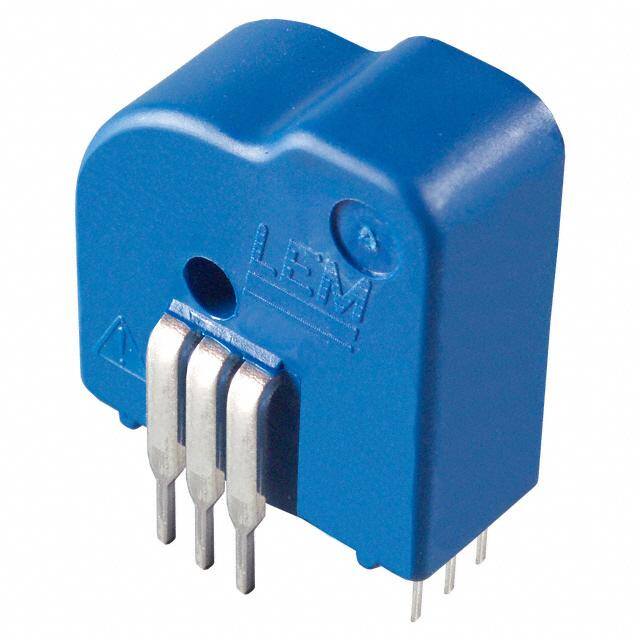
ICGOO电子元器件商城为您提供LTS 25-NP由LEM设计生产,在icgoo商城现货销售,并且可以通过原厂、代理商等渠道进行代购。 LTS 25-NP价格参考。LEMLTS 25-NP封装/规格:电流变送器, 电流传感器 25A 1 通道 霍尔效应,闭环 双向 环直径口 0.126",6 引线。您可以下载LTS 25-NP参考资料、Datasheet数据手册功能说明书,资料中有LTS 25-NP 详细功能的应用电路图电压和使用方法及教程。
LEM USA Inc.生产的LTS 25-NP是一款电流变送器,广泛应用于工业自动化、电力监控、能源管理以及设备保护等领域。以下是其主要应用场景:

1. 工业自动化系统
   LTS 25-NP可用于监测电机、驱动器和变频器的电流状态,确保设备运行在正常范围内。通过实时电流反馈,帮助优化生产效率并预防过载或短路故障。

2. 电力监控与配电系统
   在低压配电柜中,该变送器可测量负载电流,提供精确的数据用于电力平衡分析。它支持将电流信号转换为标准模拟输出(如4-20mA或0-5V),便于与SCADA系统或其他监控设备集成。

3. 能源管理系统
   该型号适用于建筑楼宇或工厂的能耗监测,帮助识别高耗能设备并制定节能策略。其高精度和稳定性确保了能源数据的可靠性。

4. 电机保护与控制
   LTS 25-NP可以检测电机启动电流和运行电流,及时发现异常情况(如堵转或过载)。结合保护继电器使用,能够有效延长电机寿命。

5. 新能源领域
   在太阳能逆变器、风力发电机组等新能源设备中,该变送器可用于电流采样,以优化能量转换效率并保障系统安全。

6. 测试与实验设备
   实验室环境中,LTS 25-NP可用于动态电流测量,为研发和测试提供准确的数据支持。

7. 家用电器与消费电子
   在高端家电(如空调、冰箱)中,该变送器可实现智能功率管理和故障诊断功能。

总结来说,LTS 25-NP以其紧凑的设计、高精度和宽量程特性,适合需要稳定电流监测的各种场合,尤其在工业和电力相关领域表现突出。
| 参数 | 数值 |
| 产品目录 | |
| 描述 | SENSOR CURRENT 25A 5V TH |
| 产品分类 | |
| 品牌 | LEM USA Inc |
| 数据手册 | |
| 产品图片 |
|
| 产品型号 | LTS 25-NP |
| rohs | 无铅 / 符合限制有害物质指令(RoHS)规范要求 |
| 产品系列 | LTS |
| 产品目录绘图 |
|
| 产品目录页面 | |
| 传感器类型 | 霍尔效应, 闭环 |
| 其它名称 | 398-1002 |
| 包装 | 散装 |
| 响应时间 | 0.4µs |
| 安装类型 | 通孔 |
| 封装/外壳 | 环直径口 0.126",6 引线 |
| 工作温度 | -40°C ~ 85°C |
| 极化 | 双向 |
| 标准包装 | 1 |
| 灵敏度 | 25mV/A |
| 用于测量 | AC/DC |
| 电压-电源 | 5V |
| 电流-检测 | 25A |
| 电流-电源(最大值) | - |
| 精度 | ±0.2% |
| 线性度 | ±0.1% |
| 输出 | 比率, 电压 |
| 通道数 | 1 |
| 频率 | DC ~ 200kHz |


- 商务部:美国ITC正式对集成电路等产品启动337调查
- 曝三星4nm工艺存在良率问题 高通将骁龙8 Gen1或转产台积电
- 太阳诱电将投资9.5亿元在常州建新厂生产MLCC 预计2023年完工
- 英特尔发布欧洲新工厂建设计划 深化IDM 2.0 战略
- 台积电先进制程称霸业界 有大客户加持明年业绩稳了
- 达到5530亿美元!SIA预计今年全球半导体销售额将创下新高
- 英特尔拟将自动驾驶子公司Mobileye上市 估值或超500亿美元
- 三星加码芯片和SET,合并消费电子和移动部门,撤换高东真等 CEO
- 三星电子宣布重大人事变动 还合并消费电子和移动部门
- 海关总署:前11个月进口集成电路产品价值2.52万亿元 增长14.8%


PDF Datasheet 数据手册内容提取
Current Transducer LTS 25-NP I = 25 At PN For the electronic measurement of currents : DC, AC, pulsed, mixed, with a galvanic isolation between the primary circuit (high power) and the secondary circuit (electronic circuit). 16054 Electrical data I Primary nominal current rms 25 At Features PN I Primary current, measuring range 0 .. ± 80 At PM • Closed loop (compensated) multi- V Output voltage (Analog) @ I 2.5±(0.625·I /I )V OUT P P PN range current transducer using the I = 0 2.5 1) V P Hall effect G Sensitivity 25 mV/A • Unipolar voltage supply N Number of secondary turns (± 0.1 %) 2000 R S Load resistance ‡ 2 kW • Isolated plastic case recognized R L Internal measuring resistance (± 0.5 %) 50 W according to UL 94-V0 IM • Compact design for PCB mounting TCR Temperature coefficient of R < 50 ppm/K IM IM • Incorporated measuring resistance V Supply voltage (± 5 %) 5 V C • Extended measuring range. I Current consumption @ V = 5 V Typ 28+I2)+(V /R)mA C C S OUT L Accuracy - Dynamic performance data Advantages • Excellent accuracy X Accuracy @ I , T = 25°C ± 0.2 % PN A • Very good linearity Accuracy with R @ I , T = 25°C ± 0.7 % e IM PN A • Very low temperature drift Linearity error < 0.1 % L • Optimized response time Typ Maxi • Wide frequency bandwidth TCVOUT Temperature coefficient of VOUT @ IP = 0 - 10°C .. + 8 5°C 50 100 ppm/K • No insertion losses - 40°C .. - 10°C 150 ppm/K • High immunity to external TCG Temperature coefficient of G - 40°C .. + 85°C 50 3) ppm/K interference VOM Magnetic offset voltage @ IP = 0, • Current overload capability. after an overload of 3 x I ± 0.5 mV PN 5 x I ± 2.0 mV Applications PN 10 x I ± 2.0 mV PN • AC variable speed drives and servo t Reaction time @ 10 % of I < 100 ns ra PN motor drives t Response time to 90 % of I step < 400 ns r PN • Static converters for DC motor drives di/dt di/dt accurately followed > 60 A/µs • Battery supplied applications BW Frequency bandwidth(0 .. - 0.5 dB) DC .. 100 kHz • Uninterruptible Power Supplies (UPS) (- 0.5 .. 1 dB) DC .. 200 kHz • Switched Mode Power Supplies (SMPS) General data • Power supplies for welding T Ambient operating temperature - 40 .. + 85 °C applications. A T Ambient storage temperature - 40 .. + 100 °C S Insulating material group III a Application domain m Mass 10 g Standards 4) EN 50178: 1997 • Industrial. IEC 60950-1: 2001 Notes: 1) Absolute value @ T = 25°C, 2.475 < V < 2.525 A OUT 2) I = I /N Copyright protected. S P S 3) Only due to TCR IM 4) Specification according to IEC 61000-4-3 are not guaranteed between 180 and 220 MHz. Page 1/3 070129/19 LEM reserves the right to carry out modifications on its transducers, in order to improve them, without prior notice. www.lem.com
Current Transducer LTS 25-NP Isolation characteristics V Rms voltage for AC isolation test, 50 Hz, 1 min 3 kV d V Impulse withstand voltage 1.2/50 µs > 8 kV W Mini V Rms voltage for partial discharge extinction @ 10pC > 1.5 kV e Mini dCp Creepage distance 5) 15.5 mm dCl Clearance distance 6) 6.35 mm CTI Comparative Tracking Index (Group III a) 175 Application examples According to EN 50178 and IEC 61010-1 standards and following conditions : • Over voltage category OV 3 • Pollution degree PD2 • Non-uniform field EN 50178 IEC 61010-1 dCp, dCI, V Rated isolation voltage Nominal voltage W Single isolation 600 V 600 V Reinforced isolation 300 V 300 V Notes: 5) On housing 6) On PCB with soldering pattern UTEC93-703. Safety This transducer must be used in electric/electronic equipment with respect to applicable standards and safety requirements in accordance with the manufacturer's operating instructions. Caution, risk of electrical shock When operating the transducer, certain parts of the module can carry hazardous voltage (eg. primary busbar, power supply). Ignoring this warning can lead to injury and/or cause serious damage. This transducer is a built-in device, whose conducting parts must be inaccessible after installation. A protective housing or additional shield could be used. Main supply must be able to be disconnected. Page 2/3 070129/19 LEM reserves the right to carry out modifications on its transducers, in order to improve them, without prior notice. www.lem.com
Dimensions LTS 25-NP (in mm. 1 mm = 0.0394 inch) Bottom view Operation principle Front view Back view Right view Number Primary nominal Nominal Primary Primary Recommended of primary current rms output voltage resistance insertion inductance connections turns I [ A ] V [ V ] R [ mW ] L [ µH ] PN OUT P P 6 5 4 OUT 1 ± 25 2.5 ± 0.625 0.18 0.013 IN 1 2 3 6 5 4 OUT 2 ± 12 2.5 ± 0.600 0.81 0.05 IN 1 2 3 6 5 4 OUT 3 ± 8 2.5 ± 0.600 1.62 0.12 IN 1 2 3 Mechanical characteristics Output Voltage - Primary Current • General tolerance ± 0.2 mm • Fastening & connection of primary 6 pins 0.8 x 0.8 mm V [ V ] OUT Recommended PCB hole 1.3 mm 5 • Fastening & connection of secondary 3 pins 0.5 x 0.35 mm 4.5 Recommended PCB hole 0.8 mm • Additional primary through-hole ˘ 3.2 mm 3.125 2.5 Remarks 1.875 • V is positive when I flows from terminals 1, 2, 3 to OUT P 0.5 terminals 6, 5, 4. • Temperature of the primary jumper should not exceed 100°C. IP [ At ] - I - I 0 I I Pmaxi PN PN Pmaxi Page 3/3 070129/19 LEM reserves the right to carry out modifications on its transducers, in order to improve them, without prior notice. www.lem.com