
 Datasheet下载
- 型号: L18P020D15
- 制造商: Tamura
- 库位|库存: xxxx|xxxx
- 要求:
| 数量阶梯 | 香港交货 | 国内含税 |
| +xxxx | $xxxx | ¥xxxx |
查看当月历史价格
查看今年历史价格
L18P020D15产品简介:
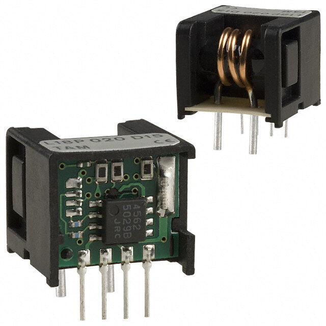
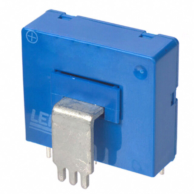
ICGOO电子元器件商城为您提供L18P020D15由Tamura设计生产,在icgoo商城现货销售,并且可以通过原厂、代理商等渠道进行代购。 L18P020D15价格参考¥43.23-¥81.01。TamuraL18P020D15封装/规格:电流变送器, 电流传感器 20A 1 通道 霍尔效应,开环 双向 模块。您可以下载L18P020D15参考资料、Datasheet数据手册功能说明书,资料中有L18P020D15 详细功能的应用电路图电压和使用方法及教程。
Tamura品牌的L18P020D15电流变送器适用于多种工业自动化和电力监控场景。该型号具备高精度、高稳定性的特点,主要用于将交流或直流电流信号转换为标准的模拟输出信号(如4-20mA或0-10V),便于PLC、DCS系统或测量仪表采集与处理。

典型应用场景包括:

1. 工业自动化控制系统:用于生产线设备、机械设备的电流监测,实现对电机、变频器等负载运行状态的实时监控。
2. 能源管理系统:在电力配电柜、智能电表中使用,进行能耗分析与电力质量监测。
3. 楼宇自控系统:应用于暖通空调(HVAC)、照明控制、电梯系统中,提升能效管理。
4. 新能源领域:如太阳能逆变器、风力发电设备中,用于电流信号采集与系统保护。
5. 电动汽车充电桩:用于监测充电过程中的电流变化,保障充电安全与效率。

L18P020D15具有良好的隔离性能和抗干扰能力,适用于复杂电磁环境,确保信号传输的稳定性与安全性,广泛应用于各类工业现场和智能控制系统中。
| 参数 | 数值 |
| 产品目录 | |
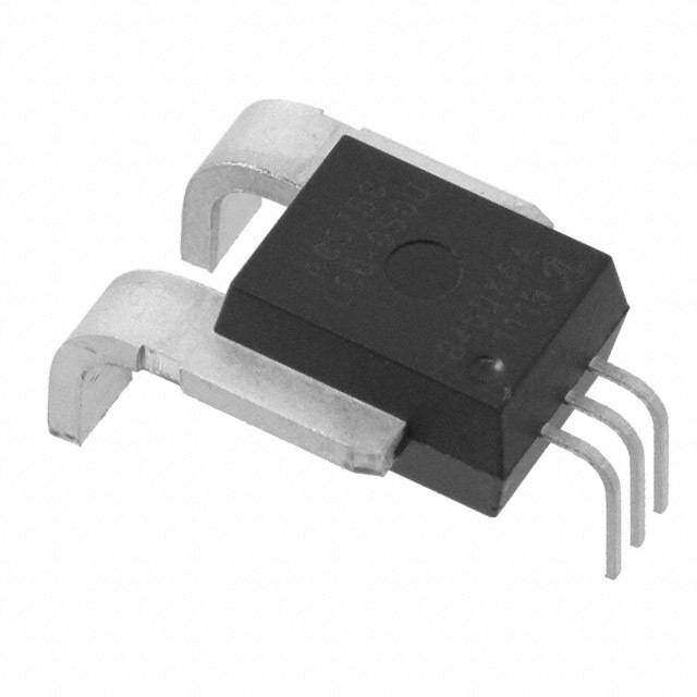
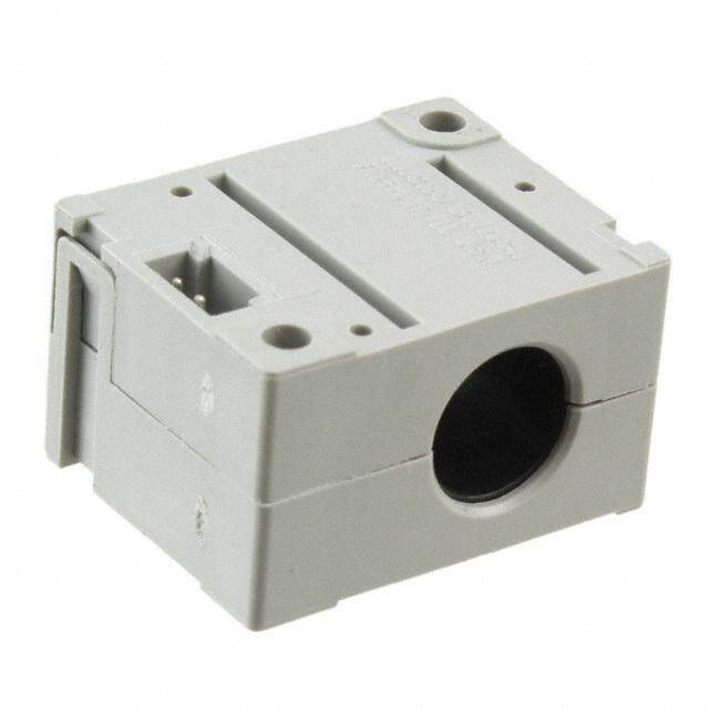
| 描述 | SENSOR CURRENT 20A -/+15V BI MOD |
| 产品分类 | |
| 品牌 | Tamura |
| 数据手册 | |
| 产品图片 |
|
| 产品型号 | L18P020D15 |
| rohs | 无铅 / 符合限制有害物质指令(RoHS)规范要求 |
| 产品系列 | - |
| 产品培训模块 | http://www.digikey.cn/PTM/IndividualPTM.page?site=cn&lang=zhs&ptm=24682 |
| 产品目录绘图 |
|
| 产品目录页面 | |
| 传感器类型 | 霍尔效应, 开环 |
| 其它名称 | MT7315 |
| 包装 | 散装 |
| 响应时间 | 5µs |
| 安装类型 | 通孔 |
| 封装/外壳 | 模块 |
| 工作温度 | -30°C ~ 80°C |
| 极化 | 双向 |
| 标准包装 | 200 |
| 灵敏度 | - |
| 用于测量 | AC/DC |
| 电压-电源 | ±15V |
| 电流-检测 | 20A |
| 电流-电源(最大值) | 15mA |
| 精度 | - |
| 线性度 | ±1% |
| 输出 | 比率, 电压 |
| 通道数 | 1 |
| 频率 | DC ~ 100kHz |


- 商务部:美国ITC正式对集成电路等产品启动337调查
- 曝三星4nm工艺存在良率问题 高通将骁龙8 Gen1或转产台积电
- 太阳诱电将投资9.5亿元在常州建新厂生产MLCC 预计2023年完工
- 英特尔发布欧洲新工厂建设计划 深化IDM 2.0 战略
- 台积电先进制程称霸业界 有大客户加持明年业绩稳了
- 达到5530亿美元!SIA预计今年全球半导体销售额将创下新高
- 英特尔拟将自动驾驶子公司Mobileye上市 估值或超500亿美元
- 三星加码芯片和SET,合并消费电子和移动部门,撤换高东真等 CEO
- 三星电子宣布重大人事变动 还合并消费电子和移动部门
- 海关总署:前11个月进口集成电路产品价值2.52万亿元 增长14.8%


PDF Datasheet 数据手册内容提取
CURRENT SENSORS L18P D15 1/1 4 1307 Magnetic Proportion System L18P D15 SERIES RoHS TATAMMUURRAA r ereccoommmmeennddss LL1188PP DD1155--OOPP sseerriieess or L1a8s Pa Dsu1c5cAeHssVio sne mrieosd eals. a succesion model. SPECIFICATIONS Ta=25˚C, RL=10kΩ, Vcc=±15V Types L18P003D15 L18P005D15 L18P010D15 L18P015D15 L18P020D15 L18P025D15 L18P030D15 L18P040D15 L18P050D15 L18P060D15 Spec Primary norminal current If 3A 5A 10A 15A 20A 25A 30A 40A 50A 60A bus-bar Primary wire φ 0.6mm 0.8mm 1.1mm 1.4mm 1.6mm 1.0×6.3 Saturation current If max If×3 Rated output voltage Vo 4V±0.040V(at If) 4V±0.050V(at If) Offset voltage Vof ≦±0.040V( at If = 0A)*1 ≦±0.050V(at If = 0A)*1 Output linearity( without offset) εL ≦±1%(at If) Power supply voltage Vcc ±15V±5% Consumption current Icc ±12mA( typ), ≦±15mA di/dt Response time tr ≦5µs(di/dt = If /µs) Thermal drift of gain TCVo ≦±0.1% / ℃(Without Tc Vof) Thermal drift of offset TCVof ≦±1.5mV / ℃ Hysteresis error VOH ≦25mV(at If = 0A → If → 0A) ≦40mV(at If = 0A → If → 0A) Insulation voltage Vd AC3000V for 1 minute(Sensing current 0.5mA)Primary ⇔ Secondary Insulation resistance RIS ≧500MΩ( at DC500V) Primary ⇔ Secondary Ambient Operating temperature TA ー30℃~+80℃ Ambient storage temperature TS ー40℃~+85℃ *1 Offset voltage value is after removal of core hysteresis. Please refer to the another sheet about conditions of UL Recognition. DIMENSIONS (mm) Lot No. Lot No. * * * The following, 17.5 * * * table references The following, table references Terminal number Terminal number 1 -Vcc 17 1 -Vcc 2 GND 2 GND 3 +Vcc 3 +Vcc 14.4 15.2 45 +OUINT 15.2 456 +-OUIINNT 6 -IN 5±1 17 4±0.5 Cu35rrAAent 00*00**35 φφφ00A..68 3 5 1.3 51.4 8.8 2.8 ±0.54 Cu45r00reAAnt *00*45*00 2-φA 6 11.5 3.75 1122305050AAAAA 000001122305050 φφφφφ11111.....14666 +-56 N1.o6 U0teAnless0 o60therwise specified, 4-□(0.25×0.5) 6- +5 11 17.5 Note tolerances shall be ±0.5mm 4 3 2 1 1. Unless otherwise specified, 4 3 2 1 2. Unit is [mm] tolerances shall be ±0.5mm 2.54±0.3 2. Unit is [mm] 4-□(0.25×0.5) 2.54±0.3 7.62 7.62 67
CURRENT SENSORS Notices 1/1 3 1510 Important Notice 1. The content of this information is subject to change without 7. This product is not designed to resist radiation. prior notice for the purpose of improvements, etc. Ensure that ・ Use in liquids such as water, oil, chemical solutions, or you are in possession of the most up-to-date information when organic solvents, and use in locations where the product will using this product. be exposed to such liquids. ・ Use that involves exposure to direct sunlight, outdoor 2. This product is intended to be used in general electronics exposure, or dusty conditions. applications (electric home appliances, business equipment, ・ Use in locations where corrosive gases such as sea winds, information equipment, communication terminal equipment, Cl2, H2S, NH3, SO2, or NO2, are present. (Some product improves durability) measuring devices, industrial equipment, and so on). This ・ Use in environments with strong static electricity or product is neither intended nor warranted for use in following electromagnetic radiation. equipment or devices: ・ Use that involves placing inflammable material next to the Special application (such as for medical devices, product. transportation equipment, traffic signal control equipment, ・Use of this product either sealed with a resin filling or coated fire and crime prevention equipment, aeronautics and with resin. space devices, nuclear power control, fuel control, in- ・Use of water or a water soluble detergent for flux cleaning. vehicle equipment, safety devices, and so on) in which ・Use in locations where condensation is liable to occur. extremely high quality and high reliability is required, or if 8. Do not use or otherwise make available the TAMUTA the malfunction or failures of product could be cause loss of products or the technology described in this document for any human life, bodily injury. military purposes, including without limitation, for the design, Tamura Corporation shall not be held responsible for any development, use, stockpiling or manufacturing of mass damage incurred by customers or any third party when products destruction weapons (e.g. nuclear, chemical, or biological are used in special application, unless specifically permitted in weapons or missile technology products). When exporting this document. and re-exporting the products or technology described in this document, you should comply with the applicable export control 3. Tamura Corporation constantly strives to improve quality and laws and regulations and follow the procedures required by reliability, but malfunction or failures are bound to occur with such laws and regulations including, without limitation, Japan some probability in current sensor. To ensure that failures do -Foreign Exchange and Foreign Trade Control Law and U.S.- not cause accidents resulting in injury or death, fire accidents, Export Administration Regulations. The TAMURA products social damage, and so on, users are to thoroughly verify the and related technology should not be used for or incorporated safety of their designs in devices and/or systems. into any products or systems whose manufacture, use, or sale 4. The operation examples and circuit examples shown in this is prohibited under any applicable domestic or foreign laws or information are for reference purposes only, and Tamura regulations. Corporation disclaims all responsibility for any violations of 9. Please contact your TAMURA sales office for details as to industrial property rights, intellectual property rights and any environmental matters such as the RoHS compatibility of other rights owned by Tamura Corporation or third parties that Product. Please use TAMURA products in compliance with all these may entail. applicable laws and regulations that regulate the inclusion or 5. The circuit examples and part constants listed in these use of controlled substances, including without limitation, the specifications are provided as reference for the verification EU RoHS Directive. TAMURA assumes no liability for damages of characteristics. The user is to perform design, verification, or losses occurring as a result of your noncompliance with and judgment under his or her own responsibility, taking into applicable laws and regulations. account the various conditions. 10. T AMURA assumes no liability for damages or losses incurred by 6. The products are designed for use in environments where you or third parties as a result of unauthorized use of TAMURA consumer electronics are commonly used. It is not designed for products. use in special environments such as listed below, and if such 11. This document and any information herein may not be use is considered, the user is to perform thorough safety and reproduced in whole or in part without prior written permission reliability checks under his/her responsibility. from TAMURA. 9
CURRENT SENSORS Appli note 1/1 3 1709 Application notes <General Considerations> <Open loop> 1. The sensor uses polar electronic components. When the 1. High frequency primary current may result in excessive heating polarity of the power supply is mistaken, the sensor is damaged. in iron magnetic core and cause damage to internal circuitry; 2. Static electricity or excessive voltage can increase an offset for high frequency applications select current sensor with ferrite voltage in the Hall element, and cause offset voltage to change. core material. Please exercise care in handling and application. 2. If the measured current exceeds the rated current, magnetic 3. In order to prevent the influence of noise, the use of twisted core saturation will occur and the output voltage signal will not cable or shielded cable for the output line is recommended be linearly proportional to the measured current. 4. If using this device within a magnetic field generated by other devices, the specified accuracy may not be obtainable. <Closed Loop> 5. Our products( several models are excluded ) are adjusted 1. For closed loop current sensors please insure the power supply with the trimming method by the measurement condition voltage is balanced, symmetrical, and, applied simultaneously (Load resistance, Power supply voltage) of specification to avoid potential increase in DC offset error. sheets. Therefore, characteristics( Offset, Output, etc.) and its 2. Maximum rated current measurement duration is timedependent. deviation may be changed in different circuit conditions from Maximum rated current applied in excess of the time limit can the measurement condition. All change characteristic items are result in damage to internal electronic circuitry; please consult not indicated on specification sheets. Tamura for assistance. 6. The performance of current sensors with through-hole( aperture) 3. When using a measurement resistor to convert current output is dependent on the position of the primary conductor. Tamura to voltage output select a resistor with stable temperature specifications are based on a primary conductor completely characteristic to insure accuracy of the output voltage. filling the through-hole( aperture) area. 4. Compensation current supplied to the secondary winding varies 7. The current sensor rated current in DC Amps. in proportion to the measured current based on the conversion 8. Please use mating connector with equivalent terminal plating ratio.( If/KN; KN = secondary turns) Please insure the PSU material to insure proper operation and avoid possibility of has required current capacity to supply compensation current ‘galvanic corrosion’. to the secondary winding. 9. Please do not store in high-temperature and high-humidity storage environment. Please use it after confirming soldering <Flux-Gate> when it is kept for six months or more.( product soldered with substrate) 1. Compensation current supplied to the secondary winding varies 10. We recommend performing a zero offset adjustment by measuring in proportion to the measured current. Please insure the PSU the offset voltage at startup. In continuously operation for a few has required current capacity to supply compensation current months, or at change of ambient temperature or humidity is large, to the secondary winding. we recommend regularly performing a zero offset adjustment at 2. There is 450kHz ripple voltage present on the output and being idling( it is clear that the current is not apply). reference output voltage signals . An external capacitor maybe 11. The current sensor doesn't have built-in protection circuit added if necessary. (devices and fuses, etc.). As a failure mode of the sensor, there is a short circuit and open state. In the case of a short- circuit state, the abnor-mal temperature rise of the internal parts is assumed, and there is a possibility to smoke and to ignite. If it is used in safety critical circuit blocks, please take appropriate measures by protection devices, protection circuits, etc. For closed loop –type sensors and flux gate (closed loop type) sensors, the consumption current of the secondary power supply varies in proportion to the measurement current. 7