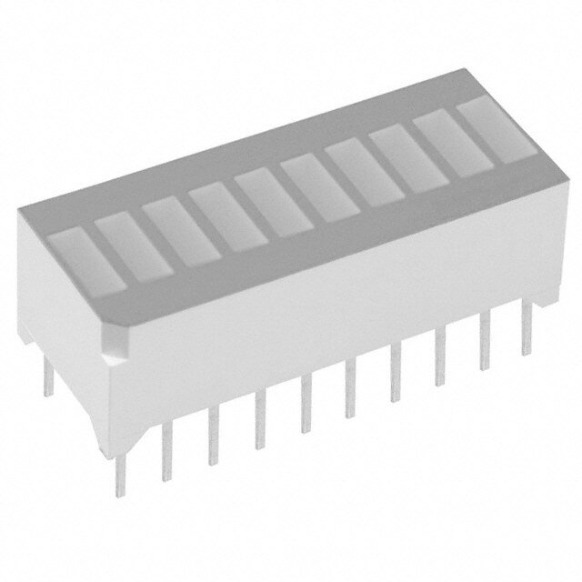
ICGOO在线商城 > 光电元件 > LED - 电路板指示器,阵列,发光条,条形图 > LTL-533-11

 Datasheet下载
- 型号: LTL-533-11
- 制造商: Lite-On
- 库位|库存: xxxx|xxxx
- 要求:
| 数量阶梯 | 香港交货 | 国内含税 |
| +xxxx | $xxxx | ¥xxxx |
查看当月历史价格
查看今年历史价格
LTL-533-11产品简介:
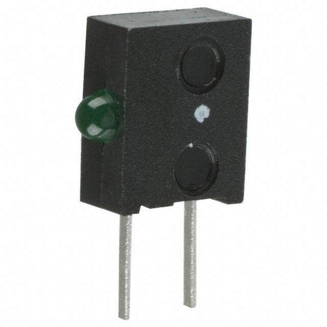
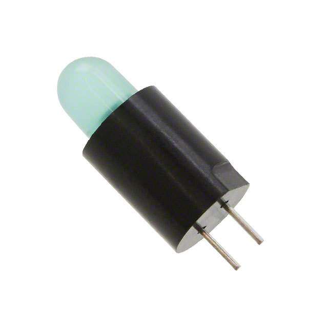
ICGOO电子元器件商城为您提供LTL-533-11由Lite-On设计生产,在icgoo商城现货销售,并且可以通过原厂、代理商等渠道进行代购。 LTL-533-11价格参考¥0.76-¥0.76。Lite-OnLTL-533-11封装/规格:LED - 电路板指示器,阵列,发光条,条形图, LED Circuit Board Indicator Single Green Diffused, Tinted 2.1V 30mA Round with Domed Top, 4.80mm Through Hole, Right Angle。您可以下载LTL-533-11参考资料、Datasheet数据手册功能说明书,资料中有LTL-533-11 详细功能的应用电路图电压和使用方法及教程。
Lite-On Inc.(广达光电)生产的LTL-533-11是一款LED电路板指示器,属于阵列、发光条或条形图类别。这类LED器件通常应用于需要直观显示状态或数据的场景中。以下是其可能的应用场景:

 1. 工业设备状态指示
   - 在工业控制面板中,LTL-533-11可以用来显示设备的工作状态,例如运行、待机、报警等。
   - 条形图形式的LED阵列可以用于显示压力、温度、电压等参数的实时变化。

 2. 消费电子设备
   - 音响设备:用于显示音量大小或音频信号强度,例如家庭影院系统或专业音响设备中的电平表。
   - 家用电器:如洗衣机、冰箱或空调的控制面板上,用作水位、温度或模式的状态指示。
   - 电脑外设:键盘背光条、鼠标充电状态指示等。

 3. 汽车电子
   - 在汽车仪表盘中,用于显示油量、电量或速度的变化趋势。
   - 车内氛围灯或功能指示灯条,增强视觉效果和功能性。

 4. 医疗设备
   - 在监护仪、血压计或其他医疗仪器中,用于显示生命体征数据,例如心率、血氧饱和度等。
   - 条形图形式的LED可以直观地反映数据变化,便于医护人员快速判断。

 5. 安防与监控
   - 在监控摄像头或门禁系统中,作为信号强度指示或工作状态提示。
   - 红外感应设备中的状态指示灯。

 6. 通信设备
   - 在路由器、交换机或网络设备中,用于显示信号强度、连接状态或数据传输速率。
   - 条形图形式的LED可以直观地反映网络负载或带宽使用情况。

 7. 广告与展示
   - 在信息显示屏或广告牌中,作为动态灯光效果的一部分,吸引观众注意力。
   - 商业展厅中的交互式灯光装置,增强用户体验。

 总结
LTL-533-11凭借其高亮度、低功耗和可靠的性能,适用于多种需要状态指示或数据可视化的场景。其条形图设计特别适合需要线性或分级显示的应用场合,能够为用户提供清晰直观的信息反馈。
| 参数 | 数值 |
| 产品目录 | |
| 描述 | LED 5MM GREEN GRN DIFF THLED 电路板指示器 Green |
| 产品分类 | |
| LED大小 | 5 mm |
| 品牌 | Lite-On |
| 产品手册 | |
| 产品图片 |
|
| rohs | 符合RoHS无铅 / 符合限制有害物质指令(RoHS)规范要求 |
| 产品系列 | LED灯泡与模块,LED 指示,LED 电路板指示器,Lite-On LTL-533-11- |
| 数据手册 | |
| 产品型号 | LTL-533-11 |
| 产品种类 | LED 电路板指示器 |
| 光强度 | 40 mcd |
| 其它名称 | 160-1977 |
| 包装 | 散装 |
| 商标 | Lite-On |
| 安装类型 | Through Hole |
| 封装 | Bulk |
| 工厂包装数量 | 500 |
| 显示角 | 60 deg |
| 标准包装 | 500 |
| 正向电压 | 2.1 V |
| 正向电流 | 20 mA |
| 毫烛光等级 | 40mcd |
| 波长 | 569 nm |
| 波长-峰值 | 565nm |
| 照明颜色 | Green |
| 电流 | 30mA |
| 视角 | 60° |
| 透镜样式/尺寸 | 圆形,带圆顶,4.8mm |
| 透镜类型 | 散射,有色 |
| 配置 | 1 Single Color LED, Single Level |
| 颜色 | 绿 |
| 额定电压 | 2.1V |


- 商务部:美国ITC正式对集成电路等产品启动337调查
- 曝三星4nm工艺存在良率问题 高通将骁龙8 Gen1或转产台积电
- 太阳诱电将投资9.5亿元在常州建新厂生产MLCC 预计2023年完工
- 英特尔发布欧洲新工厂建设计划 深化IDM 2.0 战略
- 台积电先进制程称霸业界 有大客户加持明年业绩稳了
- 达到5530亿美元!SIA预计今年全球半导体销售额将创下新高
- 英特尔拟将自动驾驶子公司Mobileye上市 估值或超500亿美元
- 三星加码芯片和SET,合并消费电子和移动部门,撤换高东真等 CEO
- 三星电子宣布重大人事变动 还合并消费电子和移动部门
- 海关总署:前11个月进口集成电路产品价值2.52万亿元 增长14.8%


PDF Datasheet 数据手册内容提取
Through Hole Lamp Product Data Sheet LTL-533-11 Spec No.: DS-20-92-0410 Effective Date: 03/10/2004 Revision: B LITE-ON DCC RELEASE BNS-OD-FC001/A4 LITE-ON Technology Corp. / Optoelectronics No.90,Chien 1 Road, Chung Ho, New Taipei City 23585, Taiwan, R.O.C. Tel: 886-2-2222-6181 Fax: 886-2-2221-1948 / 886-2-2221-0660 http://www.liteon.com/opto BBNNSS--OODD--FFCC000011//AA44 BNS-OD-FC001/A4
LITE-ON TECHNOLOGY CORPORATION Property of Lite-On Only Features * Designed for ease in circuit board assembly. * Black case enhance contrast ratio. * Solid state light source. * Reliable and rugged. Package Dimensions Lamp Source Lens Part No. Color LTL-10233WP Green Diffused Green Notes: 1. All dimensions are in millimeters (inches). 2. Tolerance is ±0.25mm(.010") unless otherwise noted. 3. The holder color is black. 4. The holder raw material is PC. 5. The LED lamp is LTL-10233WP. Part No. : LTL-533-11 Page : 1 of 6 BNS-OD-C131/A4
LITE-ON TECHNOLOGY CORPORATION Property of Lite-On Only Absolute Maximum Ratings at Ta=25℃ Parameter Maximum Rating Unit Power Dissipation 100 mW Peak Forward Current 120 mA (1/10 Duty Cycle, 0.1ms Pulse Width) DC Forward Current 30 mA Derating Linear From 50℃ 0.4 mA/℃ Reverse Voltage 5 V Operating Temperature Range -55℃ to + 100℃ Storage Temperature Range -55℃ to + 100℃ Lead Soldering Temperature 260℃ for 5 Seconds [1.6mm(.063") From Body] Part No. : LTL-533-11 Page : 2 of 6 BNS-OD-C131/A4
LITE-ON TECHNOLOGY CORPORATION Property of Lite-On Only Electrical Optical Characteristics at Ta=25℃ Part No. Parameter Symbol Min. Typ. Max. Unit Test Condition LTL- IF = 10mA Luminous Intensity IV 533-11 12.6 40 mcd Note 1,4 Viewing Angle 2θ1/2 533-11 60 deg Note 2 (Fig.6) Measurement Peak Emission Wavelength λp 533-11 565 nm @Peak (Fig.1) Dominant Wavelength λd 533-11 569 nm Note 3 Spectral Line Half-Width Δλ 533-11 30 nm Forward Voltage VF 533-11 2.1 2.6 V IF = 20mA Reverse Current IR 533-11 100 μA VR = 5V Capacitance C 533-11 35 PF VF = 0 , f = 1MHZ Note: 1. Luminous intensity is measured with a light sensor and filter combination that approximates the CIE eye-response curve. 2. θ1/2 is the off-axis angle at which the luminous intensity is half the axial luminous intensity. 3. The dominant wavelength, λd is derived from the CIE chromaticity diagram and represents the single wavelength which defines the color of the device. 4. Iv needs ±15% additionary for guaranteed limits. Part No. : LTL-533-11 Page : 3 of 6 BNS-OD-C131/A4
LITE-ON TECHNOLOGY CORPORATION Property of Lite-On Only Typical Electrical / Optical Characteristics Curves (25℃ Ambient Temperature Unless Otherwise Noted) Part No. : LTL-533-11 Page : 4 of 6 BNS-OD-C131/A4
LITE-ON TECHNOLOGY CORPORATION Property of Lite-On Only CAUTIONS 1. Application The LEDs described here are intended to be used for ordinary electronic equipment (such as office equipment, communication equipment and household applications). Consult Liteon’s Sales in advance for information on applications in which exceptional reliability is required, particularly when the failure or malfunction of the LEDs may directly jeopardize life or health (such as in aviation, transportation, traffic control equipment, medical and life support systems and safety devices). 2. Storage The storage ambient for the LEDs should not exceed 30°C temperature or 70% relative humidity. It is recommended that LEDs out of their original packaging are used within three months. For extended storage out of their original packaging, it is recommended that the LEDs be stored in a sealed container with appropriate desiccant or in a dessicator with nitrogen ambient. 3. Cleaning Use alcohol-based cleaning solvents such as isopropyl alcohol to clean the LEDs if necessary. 4. Lead Forming & Assembly During lead forming, the leads should be bent at a point at least 3mm from the base of LED lens. Do not use the base of the leadframe as a fulcrum during forming. Lead forming must be done before soldering at normal temperature. During assembly on PCB, use minimum clinch force possible to avoid excessive mechanical stress 5. Soldering When soldering, leave a minimum of 2mm clearance from the base of the lens to the soldering point. Dipping the lens into the solder must be avoided. Do not apply any external stress to the lead frame during soldering while the LED is at high temperature. Recommended soldering condition (for Lamp): Soldering iron Wave soldering Temperature 300°C Max. Pre-heat 100°C Max. Soldering time 3 sec. Max. Pre-heat time 60 sec. Max. (one time only) Solder wave 260°C Max. Soldering time 10 sec. Max. Note: Excessive soldering temperature and/or time might result in deformation of the LED lens or catastrophic failure of the LED. IR re-flow is not suitable process for through hole type LED lamp production. 6. Drive Method An LED is a current operated device, In order to ensure intensity uniformity on multiple LEDs connected in parallel in an application; it is recommended that a current limiting resistor be incorporated in the drive circuit. In series with each LED as shown in Circuit A below. (A) Recommended circuit. Circuit model A Circuit model B (B) The brightness of each LED might LED LED appear different due to the differences in the I-V characteristics of those LEDs Part No. : LTL-533-11 Page : 5 of 6 BNS-OD-C131/A4
LITE-ON TECHNOLOGY CORPORATION Property of Lite-On Only 7. Others The appearance and specifications of the product may be modified for improvement, without prior notice. Part No. : LTL-533-11 Page : 6 of 6 BNS-OD-C131/A4
Mouser Electronics Authorized Distributor Click to View Pricing, Inventory, Delivery & Lifecycle Information: L ite-On: LTL-533-11