ICGOO在线商城 > 光电元件 > LED - 电路板指示器,阵列,发光条,条形图 > HLMP-2500
 Datasheet下载
- 型号: HLMP-2500
- 制造商: Avago Technologies
- 库位|库存: xxxx|xxxx
- 要求:
| 数量阶梯 | 香港交货 | 国内含税 |
| +xxxx | $xxxx | ¥xxxx |
查看当月历史价格
查看今年历史价格
HLMP-2500产品简介:
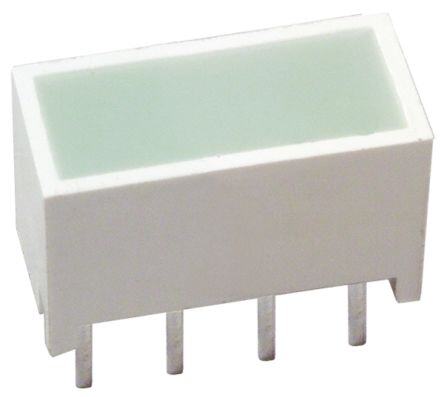
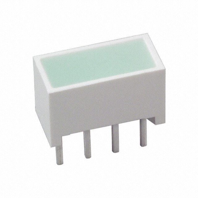
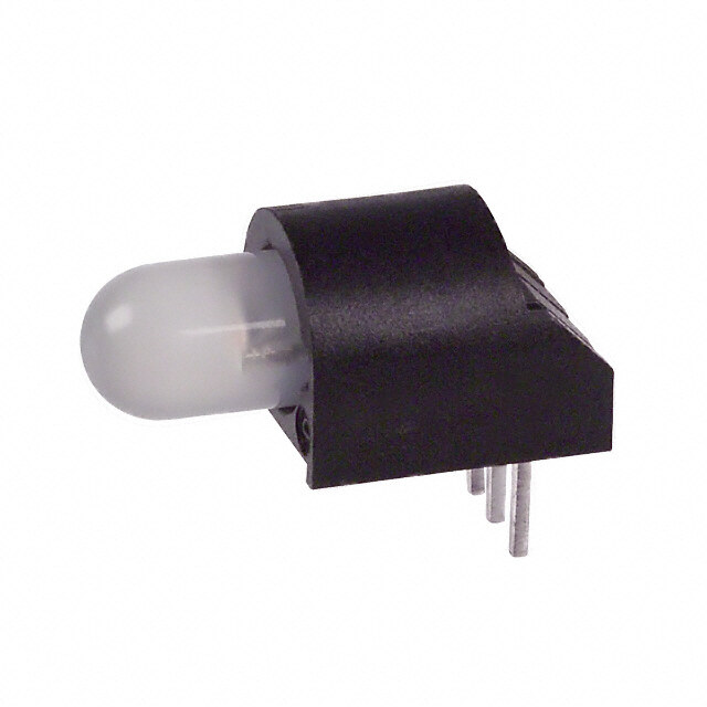
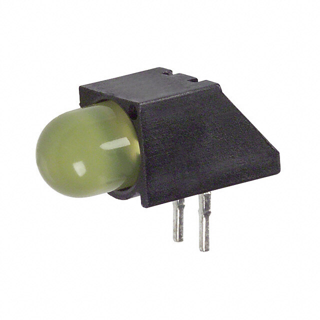
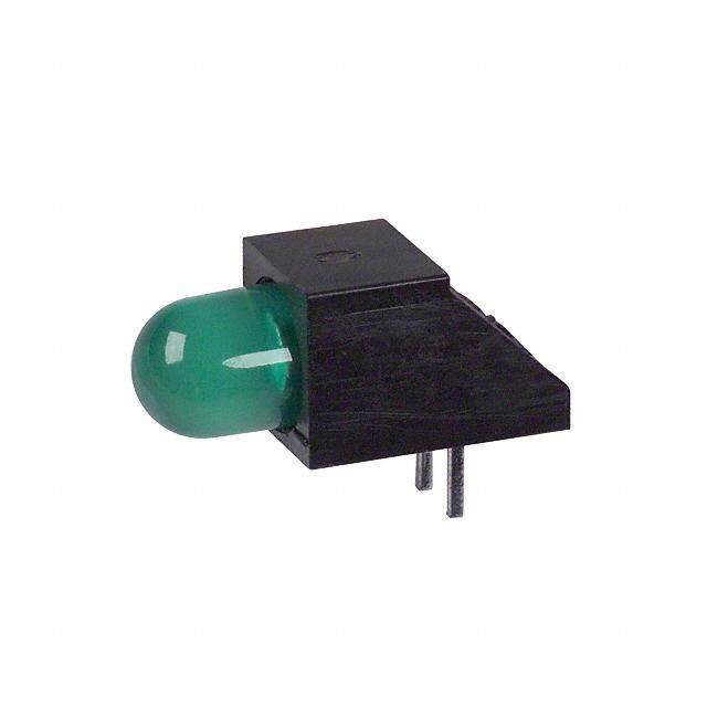
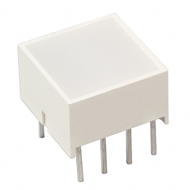
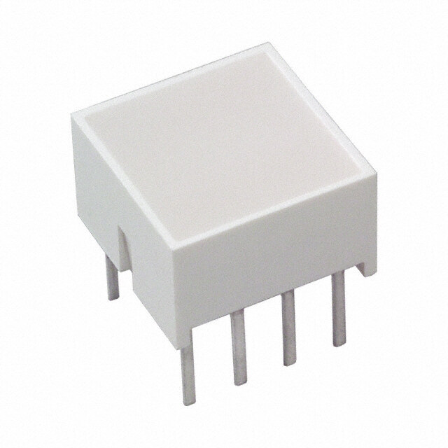
ICGOO电子元器件商城为您提供HLMP-2500由Avago Technologies设计生产,在icgoo商城现货销售,并且可以通过原厂、代理商等渠道进行代购。 HLMP-2500价格参考¥2.05-¥2.05。Avago TechnologiesHLMP-2500封装/规格:LED - 电路板指示器,阵列,发光条,条形图, LED Circuit Board Indicator Bar - Single, SIP Green 2.2V 30mA Rectangle with Flat Top, 8.89mm x 3.81mm Through Hole。您可以下载HLMP-2500参考资料、Datasheet数据手册功能说明书,资料中有HLMP-2500 详细功能的应用电路图电压和使用方法及教程。
型号为HLMP-2500的LED产品由Broadcom Limited(安华高)生产,属于LED - 电路板指示器、阵列、发光条、条形图类别。该器件是一款高亮度、双色(通常为红绿)LED指示灯,常用于电子设备中的状态指示。

HLMP-2500的典型应用场景包括:

1. 工业控制设备:用于PLC(可编程逻辑控制器)、人机界面(HMI)、工业仪表等设备中,作为运行状态、故障或电源指示灯。

2. 通信设备:在路由器、交换机、基站等通信设备中,用于指示连接状态、数据传输、电源等工作状态。

3. 消费电子产品:如音响、电视、家庭影院系统等,用于电源、静音、输入源切换等状态显示。

4. 汽车电子系统:用于车载控制面板、仪表盘、导航系统等,作为功能状态指示。

5. 测试与测量仪器:如示波器、万用表等,用于操作模式、电池电量、连接状态等提示。

HLMP-2500具有小型化、低功耗、高亮度和长寿命等特点,适合在空间有限、要求稳定性和可视性高的电子系统中使用。
| 参数 | 数值 |
| 产品目录 | |
| 描述 | LED LT BAR 8.89X3.81MM SGL GREENLED条和阵列 Green 1 Elemt 2.2 V 25 mcd |
| 产品分类 | |
| 品牌 | Avago Technologies |
| 产品手册 | http://www.avagotech.com/pages/en/led_displays/light_bars/single_color/0.4sip_single_color_series/hlmp-2500/ |
| 产品图片 |
|
| rohs | 符合RoHS无铅 / 符合限制有害物质指令(RoHS)规范要求 |
| 产品系列 | LED灯泡与模块,LED 指示,LED条和阵列,Avago Technologies HLMP-2500HLMP-2500 |
| 数据手册 | http://www.avagotech.com/docs/AV01-0692EN |
| 产品型号 | HLMP-2500 |
| PCN设计/规格 | http://www.avagotech.com/docs/29601 |
| 产品 | LED Light Bars |
| 产品目录绘图 |
|
| 产品种类 | LED条和阵列 |
| 光强度 | 25 mcd |
| 其它名称 | 516-1245-5 |
| 包装 | 管件 |
| 商标 | Avago Technologies |
| 安装类型 | 通孔 |
| 封装 | Tube |
| 工厂包装数量 | 320 |
| 标准包装 | 320 |
| 正向电压 | 2.2 V |
| 正向电流 | 20 mA |
| 毫烛光等级 | 25mcd |
| 波长-峰值 | 565nm |
| 灯杆长度 | 8.89 mm |
| 照明颜色 | Green |
| 电流 | 30mA |
| 视角 | - |
| 透镜样式/尺寸 | 矩形,8.89mm x 3.81mm |
| 透镜类型 | - |
| 配置 | 灯条 - 单灯,SIP |
| 颜色 | 绿(x 2) |
| 额定电压 | 2.2V |


- 商务部:美国ITC正式对集成电路等产品启动337调查
- 曝三星4nm工艺存在良率问题 高通将骁龙8 Gen1或转产台积电
- 太阳诱电将投资9.5亿元在常州建新厂生产MLCC 预计2023年完工
- 英特尔发布欧洲新工厂建设计划 深化IDM 2.0 战略
- 台积电先进制程称霸业界 有大客户加持明年业绩稳了
- 达到5530亿美元!SIA预计今年全球半导体销售额将创下新高
- 英特尔拟将自动驾驶子公司Mobileye上市 估值或超500亿美元
- 三星加码芯片和SET,合并消费电子和移动部门,撤换高东真等 CEO
- 三星电子宣布重大人事变动 还合并消费电子和移动部门
- 海关总署:前11个月进口集成电路产品价值2.52万亿元 增长14.8%


PDF Datasheet 数据手册内容提取
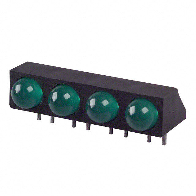
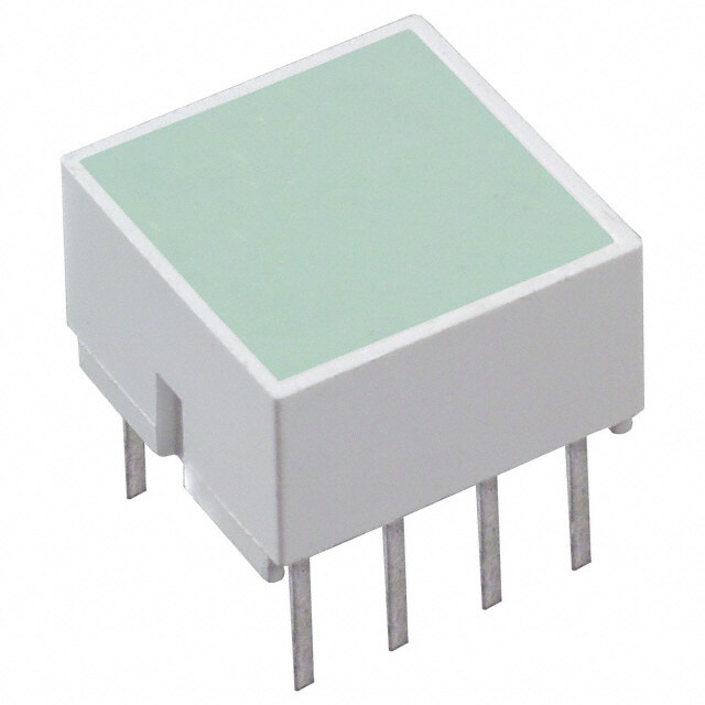
LED Light Bars HLCP-A100/-B100/-C100/D100/-E100/-F100/-G100/-H100 HLMP-2300/-2350/-2400/-2450/-2500/-2550 HLMP-2600/-2620/-2635/-2655/-2670/-2685 HLMP-2700/-2720/-2735/-2755/-2770/-2785 HLMP-2800/-2820/-2835/-2855/-2870/-2885 HLMP-2950/-2965 Data Sheet Description Features The HLCP-X100 and HLMP-2XXX series light bars • Large bright, uniform light emitting areas are rectangular light sources designed for a variety • Choice of colors of applications where a large bright source of light • Categorized for light output is required. These light bars are configured in single- in-line and dual-in-line packages that contain either • Yellow and Green categorized for dominant single or segmented light emitting areas. The Al- wavelength GaAs Red HLCP-X100 series LEDs use double hetero- • Excellent ON-OFF contrast junction AlGaAs on a GaAs substrate. The HER • X-Y stackable HLMP-2300/2600 and Yellow HLMP-2400/2700 se- ries LEDs have their p-n junctions diffused into a • Flush mountable GaAsP epitaxial layer on a GaP substrate. The Green • Can be used with panel and legend mounts HLMP-2500/2800 series LEDs use a liquid phase GaP • Light emitting surface suitable for legend attachment epitaxial layer on a GaP substrate. The bicolor HLMP- per Application Note 1012 2900 series use a combination of HER/Yellow or HER/ Green LEDs. • HLCP-X100 Series designed for low current operation • Bicolor devices available Applications • Business machine message annunciators • Telecommunications indicators • Front panel process status indicators • PC board identifiers • Bar graphs
Selection Guide Light Bar Part Number HLCP- HLMP- Size of Light Number of Light AlGaAs HER Yellow Green Emitting Areas Emitting Areas Package Outline 8.89 mm x 3.81 mm A100 2300 2400 2500 1 A (.350 in. x .150 in.) 19.05 mm x 3.81 mm B100 2350 2450 2550 1 B (.750 in. x .150 in.) 8.89 mm x 3.81 mm D100 2600 2700 2800 2 D (.350 in. x .150 in.) 8.89 mm x 3.81 mm E100 2620 2720 2820 4 E (.350 in. x .150 in.) 3.81 mm x 19.05 mm F100 2635 2735 2835 2 F (.150 in. x .750 in.) 8.89 mm x 8.89 mm C100 2655 2755 2855 1 C (.350 in. x .350 in.) 8.89 mm x 8.89 mm G100 2670 2770 2870 2 G (.350 in. x .350 in.) 8.89 mm x 19.05 mm 2685 2785 2885 1 H (.350 in. x .750 in.) 8.89 mm x 8.89 mm H100 2950 2950 Bicolor I (.350 in. x .350 in.) 8.89 mm x 8.89 mm 2965 2965 Bicolor I (.350 in. x .350 in.) 2
Part Numbering System HLCP - xx xx - xx x xx HLMP - xx xx - xx x xx Mechanical Options[1] 00: No mechanical option Color Bin Options[1,2] 0: No color bin limitation B: Color bins 2 & 3 (applicable for yellow devices only) C: Color bins 3 & 4 only (applicable for green devices only) Maximum Intensity Bin[1,2] 0: No maximum intensity bin limitation Minimum Intensity Bin[1,2] 0: No minimum intensity bin limitation Device Specific Configuration[1] Refer to respective data sheet Color[1] x1: AlGaAs Red (applicable for HLCP-x100 only) 23: High Efficiency Red 24: Yellow 25: Green 26: High Efficiency Red 27: Yellow 28: Green 29: Bicolor (High Efficiency Red/Yellow) OR (High Efficiency Red/Green) Notes: 1. For codes not listed in the figure above, please refer to the respective data sheet or contact your nearest Avago representative for details. 2. Bin options refer to shippable bins for a part-number. Color and Intensity Bins are typically restricted to 1 bin per tube (exceptions may apply). Please refer to respective data sheet for specific bin limit information. 3
Package Dimensions NOTES: 1. DIMENSIONS IN MILLIMETRES (INCHES). TOLERANCES ±0.25 mm (±0.010 IN.) UNLESS OTHERWISE INDICATED. 2. FOR YELLOW AND GREEN DEVICES ONLY. 4
Internal Circuit Diagrams 5
Absolute Maximum Ratings HER Yellow Green AlGaAs Red HLMP-2300/ HLMP-2400/ HLMP-2500/ HLCP-X100 2600/29XX 2700/2950 2800/2965 Parameter Series Series Series Series Average Power Dissipated per LED Chip 37 mW[1] 135 mW[2] 85 mW[3] 135 mW[2] Peak Forward Current per LED Chip 45 mA[4] 90 mA[5] 60 mA[5] 90 mA[5] Average Forward Current per LED Chip 15 mA 25 mA 20 mA 25 mA DC Forward Current per LED Chip 15 mA[1] 30 mA[2] 25 mA[3] 30 mA[2] Reverse Voltage* per LED Chip 5 V 6 V[6] Operating Temperature Range –20°C to +100°C[7] –40°C to +85°C –20°C to +85°C Storage Temperature Range –40°C to +85°C Wave Soldering Temperature 250°C for 3 seconds 1.6 mm (1/16 inch) below Body * Reverse Voltage is for LED testing purpose and not recommended to be used as application condition. Notes: 1. Derate above 87°C at 1.7 mW/°C per LED chip. For DC operation, derate above 91°C at 0.8 mA/°C. 2. Derate above 25°C at 1.8 mW/°C per LED chip. For DC operation, derate above 50°C at 0.5 mA/°C. 3. Derate above 50°C at 1.8 mW/°C per LED chip. For DC operation, derate above 60°C at 0.5 mA/°C. 4. See Figure 1 to establish pulsed operation. Maximum pulse width is 1.5 mS. 5. See Figure 6 to establish pulsed operation. Maximum pulse width is 2 mS. 6. Does not apply to bicolor parts. 7. For operation below –20°C, contact your local Avago sales representative. Electrical/Optical Characteristics at T = 25°C A AlGaAs Red HLCP-X100 Series Parameter HLCP- Symbol Min. Typ. Max. Units Test Conditions Luminous Intensity A100/D100/E100 I 3 7.5 mcd I = 3 mA V F per Lighting Emitting B100/C100/F100/G100 6 15 mcd Area[1] H100 12 30 mcd Peak Wavelength l 645 nm PEAK Dominant Wavelength[2] l 637 nm d Forward Voltage per LED V 1.8 2.2 V I = 20 mA F F Reverse Breakdown Voltage per LED V 5 15 V I = 100 µA R R Thermal Resistance LED Junction-to-Pin Rq 250 °C/W/ J-PIN LED 6
High Efficiency Red HLMP-2300/2600/2900 Series Parameter HLMP- Symbol Min. Typ. Max. Units Test Conditions Luminous Intensity per 2300/2600/2620 I 6 23 mcd I = 20 mA V F Lighting Emitting Area[1] 2350/2635/2655/2670/2950[3] 13 45 mcd 2965[4] 19 45 mcd 2685 22 80 mcd Peak Wavelength l 635 nm PEAK Dominant Wavelength[2] l 626 nm d Forward Voltage per LED V 2.0 2.6 V I = 20 mA F F Reverse Breakdown Voltage per LED[5] V 6 15 V I = 100 µA R R Thermal Resistance LED Junction-to-Pin Rq 150 °C/W/ J-PIN LED Yellow HLMP-2400/2700/2950 Series Parameter HLMP- Symbol Min. Typ. Max. Units Test Conditions Luminous Intensity per 2400/2700/2720 I 6 20 mcd I = 20 mA V F Lighting Emitting Area[1] 2450/2735/2755/2770/2950[3] 13 38 mcd 2785 26 70 mcd Peak Wavelength l 583 nm PEAK Dominant Wavelength[2] l 585 nm d Forward Voltage per LED V 2.1 2.6 V I = 20 mA F F Reverse Breakdown Voltage per LED[5] V 6 15 V I = 100 µA R R Thermal Resistance LED Junction-to-Pin Rq 150 °C/W/ J-PIN LED High Performance Green HLMP-2500/2800/2965 Series Parameter HLMP- Symbol Min. Typ. Max. Units Test Conditions Luminous Intensity per 2500/2800/2820 I 5 25 mcd I = 20 mA V F Lighting Emitting Area[1] 2550/2835/2855/2870 11 50 mcd 2965[4] 25 50 mcd 2885 22 100 mcd Peak Wavelength l 565 nm PEAK Dominant Wavelength[2] l 572 nm d Forward Voltage per LED V 2.2 2.6 V I = 20 mA F F Reverse Breakdown Voltage per LED[5] V 6 15 V I = 100 µA R R Thermal Resistance LED Junction-to-Pin Rq 150 °C/W/ J-PIN LED Notes: 1. These devices are categorized for luminous intensity. The intensity category is designated by a letter code on the side of the package. 2. The dominant wavelength, l, is derived from the CIE chromaticity diagram and is the single wavelength which defines the color of the device. d Yellow and Green devices are categorized for dominant wavelength with the color bin designated by a number code on the side of the package. 3. This is an HER/Yellow bicolor light bar. HER electrical/optical characteristics are shown in the HER table. Yellow electrical/optical characteristics are shown in the Yellow table. 4. This is an HER/Green bicolor light bar. HER electrical/optical characteristics are shown in the HER table. Green electrical/optical characteristics are shown in the Green table. 5. Does not apply to HLMP-2950 or HLMP-2965. 7
AlGaAs Red Figure 1. Maximum Allowable Peak Current vs. Pulse Duration. Figure 2. Maximum Allowed DC Current per LED vs. Ambient Tempera- Figure 3. Relative Efficiency (Luminous Intensity per Unit Current) vs. Peak ture, TMAX = 110°C. LED Current. J Figure 4. Forward Current vs. Forward Voltage. Figure 5. Relative Luminous Intensity vs. DC Forward Current. 8
HER, Yellow, Green Figure 6. Maximum Allowed Peak Current vs. Pulse Duration. Figure 7. Maximum Allowable DC Current per LED vs. Ambient Tempera- Figure 8. Relative Efficiency (Luminous Intensity per Unit Current) vs. Peak ture, T MAX = 100°C. LED Current. J Figure 9. Forward Current vs. Forward Voltage Characteristics. Figure 10. Relative Luminous Intensity vs. DC Forward Current. For a detailed explanation on the use of data sheet information and recommended soldering procedures, see Application Notes 1005, 1027, and 1031. 9
Intensity Bin Limits (mcd) HLMP-2400/2700/2720 Annunciators (.2 x .4 Yellow) HLMP-2300/2600/2620 Annunciators (.2 x .4 HER/AlGaAs), IV Bin Category Min. Max. HLCP-A100/D100/E100 C 6.10 11.20 D 9.20 16.80 IV Bin Category Min. Max. E 13.80 25.30 A 3.00 5.60 F 20.70 41.40 B 4.50 8.20 G 33.60 67.20 C 6.80 12.10 D 10.10 18.50 HLMP-2450/2735/2755/2770 Annunciators E 15.30 27.80 (.2 x .8 Yellow & .4 x .4 Yellow) F 22.80 45.50 IV Bin Category Min. Max. G 36.90 73.80 C 13.00 22.00 Notes: D 18.00 33.00 1. Minimum category A for Red L/C AlGaAs (-A100/-D100/-E100). 2. Minimum category C for HER (-2300/-2600/-2620). E 27.00 50.00 F 40.50 81.00 HLMP-2350/2635/2655/2670 Annunciators (.2 x .8 HER/Al- GaAs), HLCP-B100/C100/F100/G100 (.4 x .4 HER/AlGaAs) G 65.60 131.20 IV Bin Category Min. Max. HLMP-2785 Annunciators (.4 x .8 Yellow) A 5.40 10.90 IV Bin Category Min. Max. B 9.00 16.00 C 26.00 44.40 C 13.10 24.00 D 36.00 66.00 D 19.70 36.10 E 54.00 99.00 E 29.60 54.20 F 81.00 162.00 F 44.90 88.80 G 131.40 262.80 G 71.90 143.80 Notes: HLMP-2500/2800/2820 Annunciators (.2 x .4 Yellow) 1. Minimum category A for Red L/C AlGaAs (-B100/-C100/-F100/-G100). 2. Minimum category C for HER (-2350/-2635/-2670). IV Bin Category Min. Max. C 5.60 10.20 HLMP-2685/HLCP-H100 Annunciators (.4 x .8 HER/AlGaAs) D 8.40 15.30 IV Bin Category Min. Max. E 12.60 23.10 A 10.80 22.00 F 18.90 37.80 B 18.00 27.10 G 30.60 61.20 C 22.00 40.80 H 49.50 97.90 D 33.30 61.10 I 80.10 158.40 E 50.00 91.80 F 75.10 150.00 HLMP-2550/2835/2855/2870 Annunciators G 121.70 243.40 (.2 x .8/.4 x .4 Green) Notes: IV Bin Category Min. Max. 1. Minimum category A for Red L/C AlGaAs (-H100). 2. Minimum category C for HER (-2685). C 11.30 20.60 D 17.00 31.00 E 25.40 46.50 F 38.10 76.20 G 61.60 123.20 H 99.81 197.67 I 161.73 320.21 10
HLMP-2885 Annunciators (.4 x .8 Green) Color Categories IV Bin Category Min. Max. Dominant Wavelength (nm) C 22.20 40.80 Color Bin Min. Max. D 33.40 61.20 Yellow 0 579.0 582.5 E 50.10 91.90 1 581.5 585.0 F 75.10 150.30 3 584.0 587.5 G 121.10 242.20 2 586.5 590.0 H 196.10 383.50 4 589.0 592.5 I 313.70 613.60 5 591.5 595.0 Green 2 573.00 577.00 HLMP-2950 Bi-Color Annunciators (.4 x .4 HER/Yellow) 3 570.00 574.00 Red Iv Categories 4 567.00 571.00 IV Bin Category Min. Max. 5 564.00 568.00 C 11.30 20.60 Notes: D 17.00 31.00 All categories are established for classification of products. Products may not be available in all categories. Please contact your local E 25.40 46.50 Avago representatives for further clarification/information. F 38.10 76.20 G 61.60 123.20 Yellow Iv Categories IV Bin Category Min. Max. C 13.00 22.00 D 18.00 33.00 E 27.00 50.00 F 40.50 81.00 G 65.60 131.20 HLMP-2965 Bi-Color Annunciators (.4 x .4/.2 x .8 HER/Green) Red Iv Categories IV Bin Category Min. Max. D 19.70 36.10 E 29.60 54.20 F 44.90 88.80 G 71.90 143.80 Green Iv Categories IV Bin Category Min. Max. B 7.50 13.90 C 11.30 20.60 D 17.00 31.00 E 25.40 46.50 F 38.10 76.20 G 61.60 123.20 H 100.00 200.00 Notes: 1. Minimum category D for LPE Green (-2965). 2. In green mode, the devices are to be color binned into standard color bins, per Table 2. (-2685). 11
Electrical HER (HLMP-2300/2600/2900), Yellow (HLMP- 2400/2700/2900) and Green (HLMP-2500/2800/2900) These light bars are composed of two, four, or eight light series emitting diodes, with the light from each LED optically scattered to form an evenly illuminated light emitting VMAX = 1.6 + I (50 Ω) F Peak surface. For: 5 mA ≤ I ≤ 20 mA Peak The anode and cathode of each LED is brought out by VMAX = 1.8 + I (40 Ω) separate pins. This universal pinout arrangement allows F Peak the LEDs to be connected in three possible configura- For: I ≥ 20 mA Peak tions: parallel, series, or series parallel. The typical for- The maximum power dissipation can be calculated for ward voltage values can be scaled from Figures 4 and any pulsed or DC drive condition. For DC operation, 9. These values should be used to calculate the current the maximum power dissipation is the product of the limiting resistor value and typical power consumption. maximum forward voltage and the maximum forward Expected maximum V values for driver circuit design F current. For pulsed operation, the maximum power dis- and maximum power dissipation, may be calculated us- sipation is the product of the maximum forward voltage ing the following VMAX models: F at the peak forward current times the maximum average AlGaAs Red HLCP-X100 series forward current. Maximum allowable power dissipation for any given ambient temperature and thermal resist- VMAX = 1.8 V + I (20 Ω) F Peak ance (Rq ) can be deter mined by using Figure 2 or 7. The J-A For: I ≤ 20 mA solid line in Figure 2 or 7 (Rq of 600/538 C/W) represents Peak J-A a typical thermal resistance of a device socketed in a VMAX = 2.0 V + I (10 Ω) F Peak printed circuit board. The dashed lines represent achiev- For: 20 mA ≤ I ≤ 45 mA able thermal resistances that can be obtained through Peak improved thermal design. Once the maximum allowable power dissipation is determined, the maximum pulsed or DC forward current can be calculated. Optical Surface Area Size of Light Emitting Area Sq. Metres Sq. Feet I (cd) L (cd/m2) = v 8.89 mm x 8.89 mm 67.74 x 10⁻⁶ 729.16 x 10⁻⁶ v A (m2) 8.89 mm x 3.81 mm 33.87 x 10⁻⁶ 364.58 x 10⁻⁶ 8.89 mm x 19.05 mm 135.48 x 10⁻⁶ 1458.32 x 10–6 πI (cd) L (footlamberts) = v 3.81 mm x 19.05 mm 72.85 x 10⁻⁶ 781.25 x 10⁻⁶ v A (ft2) The radiation pattern for these light bar devices is ap- [ ] I proximately Lambertian. The luminous sterance may be I = AVG (ηI ) (I Data Sheet) calculated using one of the two following formulas: v TIME AVG I PEAK v TEST I (cd) wLh e(cred:/m2) = v L (cd/m2) = Iv (cd) I v = 3 mA [A1 (2m m2)A] v A (m2) TIEST = (1.18) (35 mcd) fovr T AIMElG AVaGAs Red (2H0L MmPA-Xπ0I0 (0c dse)ries) 20 mA L (footlamberts) = v L (footlamberts) = πIv (cd) forv HER, Yellow and GreAe n(f t(H2)LMP-2XXX series) v A (ft2) Example: [ ] I RoIepferreasthio rna = treess ou[flt 1IinA kVgGH i]zn o trh f(eaη smItearx pim )r (oIuvmi dD epa ottahs seSi hbmeleoe sttt)im effie aciveenrt- FIov rT IMHEL AMVGP -=2735 sIeATEVrSGiTes (ηIPEAK) (I v Data Sheet) v TIME AVG I PEAK v hI = 1.18 at I = 48 mA age luminous inteTEnSTsity. PEAK PEAK [ ] The time average luminous intensity may be calculated 12 mA using the rela[tive effic]iency character istic of Figure 3 or I = (1.18) (35 mcd) 8I, hI , a =nd ad1ju2s mteAd for( 1o.1p8e)r a(3ti5n gm cadm)bient tempera- v TIME AVG 20 mA tuvr TeIM. PETE AAhVKGe time av2e0r magAe luminous intensity at T = 25°C is = 25 mcd A calculated as follows: 12
The time average luminous intensity may be adjusted for Mechanical operating ambient temperature by the following expo- These light bar devices may be operated in ambient tem- nential equation: peratures above +60°C without derating when installed I (T) = I (25°C)e[K (T –25°C)] in a PC board configuration that provides a thermal re- v A V sistance pin to ambient value less than 280°C/W/LED. See Figure 2 or 7 to determine the maximum allowed ther- Color K mal resistance for the PC board, Rq , which will permit PC-A nonderated operation in a given ambient temperature. AlGaAs Red –0.0095/°C To optimize device optical performance, specially devel- HER –0.0131/°C oped plastics are used which restrict the solvents that Yellow –0.0112/°C may be used for cleaning. It is recommended that only Green –0.0104/°C mixtures of Freon (F113) and alcohol be used for vapor cleaning processes, with an immersion time in the va- Example: pors of less than two (2) minutes maximum. Some sug- gested vapor cleaning solvents are Freon TE, Genesolv I (80°C) = (25 mcd)e[-0.0112 (80-25)] v DES, Arklone A or K. A 60°C (140°F) water cleaning pro- = 14 mcd. cess may also be used, which includes a neutralizer rinse (3% ammonia solution or equivalent), a surfactant rinse (1% detergent solution or equivalent), a hot water rinse and a thorough air dry. Room temperature cleaning may be accomplished with Freon T-E35 or T-P35, Ethanol, Iso- propanol or water with a mild detergent. For further information on soldering LEDs please refer to Application Note 1027. For product information and a complete list of distributors, please go to our web site: www.avagotech.com Avago, Avago Technologies, and the A logo are trademarks of Avago Technologies in the United States and other countries. Data subject to change. Copyright © 2005-2015 Avago Technologies. All rights reserved. Obsoletes AV01-0692EN AV02-4479EN - May 26, 2015
Mouser Electronics Authorized Distributor Click to View Pricing, Inventory, Delivery & Lifecycle Information: B roadcom Limited: HLCP-A100 HLCP-A100-BC000 HLCP-B100 HLCP-B100-BC000 HLCP-C100 HLCP-D100 HLCP-D100-BC000 HLCP-E100 HLCP-E100-BC000 HLCP-G100 HLCP-H100 HLCP-J100 HLMP-2300 HLMP-2300-EF000 HLMP- 2350 HLMP-2350-EF000 HLMP-2400 HLMP-2400-EF000 HLMP-2450 HLMP-2450-EF000 HLMP-2500 HLMP- 2500-FG000 HLMP-2550 HLMP-2550-FG000 HLMP-2600 HLMP-2620 HLMP-2620-EF000 HLMP-2655 HLMP- 2655-EF000 HLMP-2670 HLMP-2685 HLMP-2685-EF000 HLMP-2700 HLMP-2700-EF000 HLMP-2720 HLMP- 2720-EF000 HLMP-2755 HLMP-2755-EF000 HLMP-2770 HLMP-2785 HLMP-2785-EF000 HLMP-2785-EFB00 HLMP-2800 HLMP-2820 HLMP-2820-FG000 HLMP-2855 HLMP-2855-FG000 HLMP-2870 HLMP-2870-FG000 HLMP-2885 HLMP-2885-FG000 HLMP-2950 HLMP-2965