ICGOO在线商城 > 集成电路(IC) > 嵌入式 - CPLD(复杂可编程逻辑器件) > LC4032V-75TN48C

 Datasheet下载
- 型号: LC4032V-75TN48C
- 制造商: Lattice
- 库位|库存: xxxx|xxxx
- 要求:
| 数量阶梯 | 香港交货 | 国内含税 |
| +xxxx | $xxxx | ¥xxxx |
查看当月历史价格
查看今年历史价格
LC4032V-75TN48C产品简介:
ICGOO电子元器件商城为您提供LC4032V-75TN48C由Lattice设计生产,在icgoo商城现货销售,并且可以通过原厂、代理商等渠道进行代购。 LC4032V-75TN48C价格参考。LatticeLC4032V-75TN48C封装/规格:嵌入式 - CPLD(复杂可编程逻辑器件), 。您可以下载LC4032V-75TN48C参考资料、Datasheet数据手册功能说明书,资料中有LC4032V-75TN48C 详细功能的应用电路图电压和使用方法及教程。
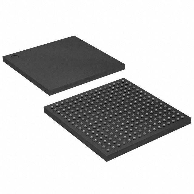
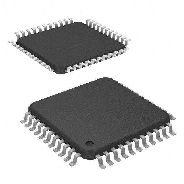
LC4032V-75TN48C 是 Lattice Semiconductor Corporation 生产的一款嵌入式 CPLD(复杂可编程逻辑器件),属于 Lattice ispMACH 4000V 系列。该型号具有低功耗、高密度逻辑功能和灵活的 I/O 配置,适用于多种应用场景。以下是其主要应用场景及特点:

 1. 工业自动化
   - 应用:用于控制接口、信号调理和协议转换。
   - 特点:LC4032V 提供丰富的 I/O 资源和逻辑单元,能够实现复杂的时序控制和数据处理,适合工业环境中对可靠性和实时性要求较高的场景。

 2. 通信设备
   - 应用:用作数据包处理、协议桥接或信号同步。
   - 特点:支持高速信号传输和多协议兼容,能够在通信系统中实现灵活的功能扩展和定制化设计。

 3. 消费电子
   - 应用:用于桥接不同接口(如 USB、SPI、I2C)或实现简单的控制逻辑。
   - 特点:低功耗设计使其非常适合电池供电的便携式设备,同时其小型封装(如 TN48C)节省了 PCB 空间。

 4. 汽车电子
   - 应用:用于传感器信号处理、总线桥接或车载娱乐系统的功能扩展。
   - 特点:具备良好的抗噪能力和稳定性,能够在恶劣环境下正常工作。

 5. 医疗设备
   - 应用:用于患者监测设备中的信号采集与处理,或实现设备的接口适配。
   - 特点:提供可靠的逻辑功能和低延迟性能,满足医疗设备对精度和稳定性的严格要求。

 6. 航空航天与国防
   - 应用:用于关键任务中的信号处理、数据加密或接口转换。
   - 特点:经过优化的低功耗特性和高可靠性,使其适合对功耗和性能有严格要求的特殊环境。

 技术特性
- 逻辑单元:3200 个逻辑单元,支持复杂的数字逻辑设计。
- I/O 数量:多达 128 个用户 I/O,提供灵活的外部连接能力。
- 工作电压:1.2V 内核电压,支持低功耗运行。
- 封装形式:48 引脚 TQFP 封装(TN48C),适合紧凑型设计。

总结来说,LC4032V-75TN48C 凭借其高性能、低功耗和灵活性,广泛应用于需要高效逻辑处理和接口适配的场景,尤其适合对成本敏感且空间受限的设计项目。
| 参数 | 数值 |
| 产品目录 | 集成电路 (IC)半导体 |
| 描述 | IC CPLD 32MC 7.5NS 48TQFPCPLD - 复杂可编程逻辑器件 400 MHZ 32 Macrocell 3.3 V 7.5 tPD |
| 产品分类 | |
| I/O数 | 32 |
| 品牌 | Lattice Semiconductor Corporation |
| 产品手册 | |
| 产品图片 |
|
| rohs | 符合RoHS无铅 / 符合限制有害物质指令(RoHS)规范要求 |
| 产品系列 | 嵌入式处理器和控制器,CPLD - 复杂可编程逻辑器件,Lattice LC4032V-75TN48CispMACH® 4000V |
| 数据手册 | |
| 产品型号 | LC4032V-75TN48C |
| PCN设计/规格 | http://www.latticesemi.com/~/media/Documents/ProductChangeNotification/13/PCN03A-13_Alternate_Qualified_Assembly_Test%20Site_Material_Sets_ASE_Taiwan.ashx |
| 产品 | ispMACH 4032 |
| 产品种类 | CPLD - 复杂可编程逻辑器件 |
| 供应商器件封装 | 48-TQFP(7x7) |
| 其它名称 | 220-1033 |
| 包装 | 托盘 |
| 可编程类型 | 系统内可编程 |
| 商标 | Lattice |
| 大电池数量 | 32 |
| 存储类型 | EEPROM |
| 安装类型 | 表面贴装 |
| 安装风格 | SMD/SMT |
| 宏单元数 | 32 |
| 封装 | Tray |
| 封装/外壳 | 48-LQFP |
| 封装/箱体 | TQFP-48 |
| 工作温度 | 0°C ~ 90°C |
| 工作电源电压 | 3.3 V |
| 工作电源电流 | 11.8 mA |
| 工厂包装数量 | 250 |
| 延迟时间 | 2.5 ns |
| 延迟时间tpd(1)最大值 | 7.5ns |
| 最大工作温度 | + 70 C |
| 最大工作频率 | 400 MHz |
| 最小工作温度 | 0 C |
| 栅极数 | - |
| 标准包装 | 250 |
| 每个宏指令的积项数 | 80 |
| 电源电压-内部 | 3 V ~ 3.6 V |
| 电源电压-最大 | 3.6 V |
| 电源电压-最小 | 3 V |
| 系列 | LC4032V-75TN |
| 输入/输出端数量 | 208 |
| 逻辑元件/块数 | 2 |
| 逻辑数组块数量——LAB | 2 |


- 商务部:美国ITC正式对集成电路等产品启动337调查
- 曝三星4nm工艺存在良率问题 高通将骁龙8 Gen1或转产台积电
- 太阳诱电将投资9.5亿元在常州建新厂生产MLCC 预计2023年完工
- 英特尔发布欧洲新工厂建设计划 深化IDM 2.0 战略
- 台积电先进制程称霸业界 有大客户加持明年业绩稳了
- 达到5530亿美元!SIA预计今年全球半导体销售额将创下新高
- 英特尔拟将自动驾驶子公司Mobileye上市 估值或超500亿美元
- 三星加码芯片和SET,合并消费电子和移动部门,撤换高东真等 CEO
- 三星电子宣布重大人事变动 还合并消费电子和移动部门
- 海关总署:前11个月进口集成电路产品价值2.52万亿元 增长14.8%


PDF Datasheet 数据手册内容提取
ispMACH® 4000V/B/C/Z Family 3.3 V/2.5 V/1.8 V In-System Programmable SuperFAST TMHigh Density PLDs April 2016 Data Sheet DS1020 Features Broad Device Offering (cid:129) Multiple temperature range support High Performance – Commercial: 0 to 90 °C junction (T) j (cid:129) f = 400 MHz maximum operating frequency MAX – Industrial: –40 to 105 °C junction (T) j (cid:129) t = 2.5 ns propagation delay PD – Extended: –40 to 130 °C junction (T) j (cid:129) Up to four global clock pins with programmable (cid:129) For AEC-Q100 compliant devices, refer to clock polarity control LA-ispMACH 4000V/Z Automotive Data Sheet (cid:129) Up to 80 PTs per output Easy System Integration Ease of Design (cid:129) Superior solution for power sensitive consumer (cid:129) Enhanced macrocells with individual clock, applications reset, preset and clock enable controls (cid:129) Operation with 3.3 V, 2.5 V or 1.8 V LVCMOS I/O (cid:129) Up to four global OE controls (cid:129) Operation with 3.3 V (4000V), 2.5 V (4000B) or (cid:129) Individual local OE control per I/O pin 1.8 V (4000C/Z) supplies (cid:129) Excellent First-Time-FitTM and refit (cid:129) 5 V tolerant I/O for LVCMOS 3.3, LVTTL, and (cid:129) Fast path, SpeedLockingTM Path, and wide-PT PCI interfaces path (cid:129) Hot-socketing (cid:129) Wide input gating (36 input logic blocks) for fast (cid:129) Open-drain capability counters, state machines and address decoders (cid:129) Input pull-up, pull-down or bus-keeper Zero Power (ispMACH 4000Z) and Low (cid:129) Programmable output slew rate Power (ispMACH 4000V/B/C) (cid:129) 3.3 V PCI compatible (cid:129) Typical static current 10 µA (4032Z) (cid:129) IEEE 1149.1 boundary scan testable (cid:129) Typical static current 1.3 mA (4000C) (cid:129) 3.3 V/2.5 V/1.8 V In-System Programmable (cid:129) 1.8 V core low dynamic power (ISP™) using IEEE 1532 compliant interface (cid:129) ispMACH 4000Z operational down to 1.6 V V (cid:129) I/O pins with fast setup path CC (cid:129) Lead-free package options Table1.ispMACH 4000V/B/C Family Selection Guide ispMACH ispMACH ispMACH ispMACH ispMACH ispMACH 4032V/B/C 4064V/B/C 4128V/B/C 4256V/B/C 4384V/B/C 4512V/B/C Macrocells 32 64 128 256 384 512 I/O + Dedicated Inputs 30+2/32+4 30+2/32+4/ 64+10/92+4/ 64+10/96+14/ 128+4/192+4 128+4/208+4 64+10 96+4 128+4/160+4 t (ns) 2.5 2.5 2.7 3.0 3.5 3.5 PD t (ns) 1.8 1.8 1.8 2.0 2.0 2.0 S t (ns) 2.2 2.2 2.7 2.7 2.7 2.7 CO f (MHz) 400 400 333 322 322 322 MAX Supply Voltages (V) 3.3/2.5/1.8V 3.3/2.5/1.8V 3.3/2.5/1.8V 3.3/2.5/1.8V 3.3/2.5/1.8V 3.3/2.5/1.8V Pins/Package 44 TQFP4 44 TQFP4 48 TQFP4 48 TQFP4 100 TQFP 100 TQFP 100 TQFP 128 TQFP 144 TQFP1 144 TQFP1 176 TQFP 176 TQFP 176 TQFP 256 ftBGA2/ 256 ftBGA/ 256 ftBGA/ fpBGA2, 3 fpBGA3 fpBGA3 1. 3.3 V (4000V) only. 2. 128-I/O and 160-I/O configurations. 3. Use 256 ftBGA package for all new designs. Refer to PCN#14A-07 for 256 fpBGA package discontinuance. 4. 1.0 mm thickness. © 2016 Lattice Semiconductor Corp. All Lattice trademarks, registered trademarks, patents, and disclaimers are as listed at www.latticesemi.com/legal. All other brand or product names are trademarks or registered trademarks of their respective holders. The specifications and information herein are subject to change without notice. www.latticesemi.com 1 DS1020_23.5
ispMACH 4000V/B/C/Z Family Data Sheet Table2.ispMACH 4000Z Family Selection Guide ispMACH 4032ZC ispMACH 4064ZC ispMACH 4128ZC ispMACH 4256ZC Macrocells 32 64 128 256 I/O + Dedicated Inputs 32+4/32+4 32+4/32+12/ 64+10/96+4 64+10/96+6/ 64+10/64+10 128+4 t (ns) 3.5 3.7 4.2 4.5 PD t (ns) 2.2 2.5 2.7 2.9 S t (ns) 3.0 3.2 3.5 3.8 CO f (MHz) 267 250 220 200 MAX Supply Voltage (V) 1.8 1.8 1.8 1.8 Max. Standby Icc (µA) 20 25 35 55 Pins/Package 48 TQFP 48 TQFP 56 csBGA 56 csBGA 100 TQFP 100 TQFP 100 TQFP 132 csBGA 132csBGA 132 csBGA 176 TQFP ispMACH 4000 Introduction The high performance ispMACH 4000 family from Lattice offers a SuperFAST CPLD solution. The family is a blend of Lattice’s two most popular architectures: the ispLSI® 2000 and ispMACH 4A. Retaining the best of both families, the ispMACH 4000 architecture focuses on significant innovations to combine the highest performance with low power in a flexible CPLD family. The ispMACH 4000 combines high speed and low power with the flexibility needed for ease of design. With its robust Global Routing Pool and Output Routing Pool, this family delivers excellent First-Time-Fit, timing predictabil- ity, routing, pin-out retention and density migration. The ispMACH 4000 family offers densities ranging from 32 to 512 macrocells. There are multiple density-I/O com- binations in Thin Quad Flat Pack (TQFP), Chip Scale BGA (csBGA) and Fine Pitch Thin BGA (ftBGA) packages ranging from 44 to 256 pins/balls. Table1 shows the macrocell, package and I/O options, along with other key parameters. The ispMACH 4000 family has enhanced system integration capabilities. It supports 3.3 V (4000V), 2.5 V (4000B) and 1.8 V (4000C/Z) supply voltages and 3.3 V, 2.5 V and 1.8 V interface voltages. Additionally, inputs can be safely driven up to 5.5 V when an I/O bank is configured for 3.3 V operation, making this family 5 V tolerant. The ispMACH 4000 also offers enhanced I/O features such as slew rate control, PCI compatibility, bus-keeper latches, pull-up resistors, pull-down resistors, open drain outputs and hot socketing. The ispMACH 4000 family members are 3.3 V/2.5 V/1.8 V in-system programmable through the IEEE Standard 1532 interface. IEEE Standard 1149.1 boundary scan testing capability also allows product testing on automated test equipment. The 1532 interface sig- nals TCK, TMS, TDI and TDO are referenced to V (logic core). CC Overview The ispMACH 4000 devices consist of multiple 36-input, 16-macrocell Generic Logic Blocks (GLBs) interconnected by a Global Routing Pool (GRP). Output Routing Pools (ORPs) connect the GLBs to the I/O Blocks (IOBs), which contain multiple I/O cells. This architecture is shown in Figure1. 2
ispMACH 4000V/B/C/Z Family Data Sheet Figure1.Functional Block Diagram CCO0ND LK0/ILK1/ILK2/ILK3/I OE0OE1 CCND CKMSDIDO CCO1ND VG CCCC GG VG TTTT VG I/O I/O Block 16 16 Block Generic Generic ORP 16 Logic Logic 16 ORP Block 36 ol 36 Block o P nk 0 uting nk 1 a o a B R B O al O I/ b I/ o Gl I/O I/O 16 16 Block Generic Generic Block ORP 16 Logic Logic 16 ORP 36 36 Block Block The I/Os in the ispMACH 4000 are split into two banks. Each bank has a separate I/O power supply. Inputs can support a variety of standards independent of the chip or bank power supply. Outputs support the standards com- patible with the power supply provided to the bank. Support for a variety of standards helps designers implement designs in mixed voltage environments. In addition, 5 V tolerant inputs are specified within an I/O bank that is con- nected to V of 3.0 V to 3.6 V for LVCMOS 3.3, LVTTL and PCI interfaces. CCO ispMACH 4000 Architecture There are a total of two GLBs in the ispMACH 4032, increasing to 32 GLBs in the ispMACH 4512. Each GLB has 36 inputs. All GLB inputs come from the GRP and all outputs from the GLB are brought back into the GRP to be connected to the inputs of any other GLB on the device. Even if feedback signals return to the same GLB, they still must go through the GRP. This mechanism ensures that GLBs communicate with each other with consistent and predictable delays. The outputs from the GLB are also sent to the ORP. The ORP then sends them to the associ- ated I/O cells in the I/O block. Generic Logic Block The ispMACH 4000 GLB consists of a programmable AND array, logic allocator, 16 macrocells and a GLB clock generator. Macrocells are decoupled from the product terms through the logic allocator and the I/O pins are decou- pled from macrocells through the ORP. Figure2 illustrates the GLB. 3
ispMACH 4000V/B/C/Z Family Data Sheet Figure2.Generic Logic Block To GRP 0 1 2 3 K K K K L L L L C C C C Clock Generator 1+OE als 1+OE n g Si ack 1+OE f3ro6m In GpuRtPs AND Array36 Inputs, Product Terms Logic Allocator 16 Macrocells 16 MC Feedb 11++OOEE To ORP 3 8 1+OE 1+OE 1+OE To Product Term Output Enable Sharing AND Array The programmable AND Array consists of 36 inputs and 83 output product terms. The 36 inputs from the GRP are used to form 72 lines in the AND Array (true and complement of the inputs). Each line in the array can be con- nected to any of the 83 output product terms via a wired-AND. Each of the 80 logic product terms feed the logic allocator with the remaining three control product terms feeding the Shared PT Clock, Shared PT Initialization and Shared PT OE. The Shared PT Clock and Shared PT Initialization signals can optionally be inverted before being fed to the macrocells. Every set of five product terms from the 80 logic product terms forms a product term cluster starting with PT0. There is one product term cluster for every macrocell in the GLB. Figure3 is a graphical representation of the AND Array. 4
ispMACH 4000V/B/C/Z Family Data Sheet Figure3.AND Array In[0] In[34] In[35] PT0 PT1 PT2 Cluster 0 PT3 PT4 PT75 PT76 PT77 Cluster 15 PT78 PT79 PT80 Shared PT Clock PT81 Shared PT Initialization PT82 Shared PTOE Note: Indicates programmable fuse. Enhanced Logic Allocator Within the logic allocator, product terms are allocated to macrocells in product term clusters. Each product term cluster is associated with a macrocell. The cluster size for the ispMACH 4000 family is 4+1 (total 5) product terms. The software automatically considers the availability and distribution of product term clusters as it fits the functions within a GLB. The logic allocator is designed to provide three speed paths: 5-PT fast bypass path, 20-PT Speed Locking path and an up to 80-PT path. The availability of these three paths lets designers trade timing variability for increased performance. The enhanced Logic Allocator of the ispMACH 4000 family consists of the following blocks: (cid:129) Product Term Allocator (cid:129) Cluster Allocator (cid:129) Wide Steering Logic Figure4 shows a macrocell slice of the Logic Allocator. There are 16 such slices in the GLB. 5
ispMACH 4000V/B/C/Z Family Data Sheet Figure4.Macrocell Slice to to from from n-1 n-2 n-1 n-4 Fast 5-PT Path From 1-80 n-4 PTs 5-PT n To XOR (MC) Cluster to from from n+1 n+2 n+1 To n+4 Individual Product Cluster SuperWIDE™ Term Allocator Allocator Steering Logic Product Term Allocator The product term allocator assigns product terms from a cluster to either logic or control applications as required by the design being implemented. Product terms that are used as logic are steered into a 5-input OR gate associ- ated with the cluster. Product terms that used for control are steered either to the macrocell or I/O cell associated with the cluster. Table3 shows the available functions for each of the five product terms in the cluster. The OR gate output connects to the associated I/O cell, providing a fast path for narrow combinatorial functions, and to the logic allocator. Table3.Individual PT Steering Product Term Logic Control PTn Logic PT Single PT for XOR/OR PTn+1 Logic PT Individual Clock (PT Clock) PTn+2 Logic PT Individual Initialization or Individual Clock Enable (PT Initialization/CE) PTn+3 Logic PT Individual Initialization (PT Initialization) PTn+4 Logic PT Individual OE (PTOE) Cluster Allocator The cluster allocator allows clusters to be steered to neighboring macrocells, thus allowing the creation of functions with more product terms. Table4 shows which clusters can be steered to which macrocells. Used in this manner, the cluster allocator can be used to form functions of up to 20 product terms. Additionally, the cluster allocator accepts inputs from the wide steering logic. Using these inputs, functions up to 80 product terms can be created. Table4.Available Clusters for Each Macrocell Macrocell Available Clusters M0 — C0 C1 C2 M1 C0 C1 C2 C3 M2 C1 C2 C3 C4 M3 C2 C3 C4 C5 M4 C3 C4 C5 C6 M5 C4 C5 C6 C7 M6 C5 C6 C7 C8 6
ispMACH 4000V/B/C/Z Family Data Sheet Macrocell Available Clusters M7 C6 C7 C8 C9 M8 C7 C8 C9 C10 M9 C8 C9 C10 C11 M10 C9 C10 C11 C12 M11 C10 C11 C12 C13 M12 C11 C12 C13 C14 M13 C12 C13 C14 C15 M14 C13 C14 C15 — M15 C14 C15 — — Wide Steering Logic The wide steering logic allows the output of the cluster allocator n to be connected to the input of the cluster alloca- tor n+4. Thus, cluster chains can be formed with up to 80 product terms, supporting wide product term functions and allowing performance to be increased through a single GLB implementation. Table5 shows the product term chains. Table5.Product Term Expansion Capability Expansion Macrocells Associated with Expansion Chain Max PT/ Chains (with Wrap Around) Macrocell Chain-0 M0 ? M4 ? M8 ? M12 ? M0 75 Chain-1 M1 ? M5 ? M9 ? M13 ? M1 80 Chain-2 M2 ? M6 ? M10 ? M14 ? M2 75 Chain-3 M3 ? M7 ? M11 ? M15 ? M3 70 Every time the super cluster allocator is used, there is an incremental delay of t . When the super cluster alloca- EXP tor is used, all destinations other than the one being steered to, are given the value of ground (i.e., if the super clus- ter is steered to M (n+4), then M (n) is ground). Macrocell The 16 macrocells in the GLB are driven by the 16 outputs from the logic allocator. Each macrocell contains a pro- grammable XOR gate, a programmable register/latch, along with routing for the logic and control functions. Figure5 shows a graphical representation of the macrocell. The macrocells feed the ORP and GRP. A direct input from the I/O cell allows designers to use the macrocell to construct high-speed input registers. A programmable delay in this path allows designers to choose between the fastest possible set-up time and zero hold time. 7
ispMACH 4000V/B/C/Z Family Data Sheet Figure5.Macrocell Power-up Initialization Shared PT Initialization PT Initialization (optional) PT Initialization/CE (optional) Delay From I/O Cell From Logic Allocator R P To ORP D/T/L Q To GRP CE Block CLK0 Single PT Block CLK1 Block CLK2 Block CLK3 PT Clock (optional) Shared PT Clock Enhanced Clock Multiplexer The clock input to the flip-flop can select any of the four block clocks along with the shared PT clock, and true and complement forms of the optional individual term clock. An 8:1 multiplexer structure is used to select the clock. The eight sources for the clock multiplexer are as follows: (cid:129) Block CLK0 (cid:129) Block CLK1 (cid:129) Block CLK2 (cid:129) Block CLK3 (cid:129) PT Clock (cid:129) PT Clock Inverted (cid:129) Shared PT Clock (cid:129) Ground Clock Enable Multiplexer Each macrocell has a 4:1 clock enable multiplexer. This allows the clock enable signal to be selected from the fol- lowing four sources: (cid:129) PT Initialization/CE (cid:129) PT Initialization/CE Inverted (cid:129) Shared PT Clock (cid:129) Logic High Initialization Control The ispMACH 4000 family architecture accommodates both block-level and macrocell-level set and reset capability. There is one block-level initialization term that is distributed to all macrocell registers in a GLB. At the macrocell level, two product terms can be “stolen” from the cluster associated with a macrocell to be used for set/reset func- 8
ispMACH 4000V/B/C/Z Family Data Sheet tionality. A reset/preset swapping feature in each macrocell allows for reset and preset to be exchanged, providing flexibility. Note that the reset/preset swapping selection feature affects power-up reset as well. All flip-flops power up to a known state for predictable system initialization. If a macrocell is configured to SET on a signal from the block-level initialization, then that macrocell will be SET during device power-up. If a macrocell is configured to RESET on a signal from the block-level initialization or is not configured for set/reset, then that macrocell will RESET on power- up. To guarantee initialization values, the V rise must be monotonic, and the clock must be inactive until the reset CC delay time has elapsed. GLB Clock Generator Each ispMACH 4000 device has up to four clock pins that are also routed to the GRP to be used as inputs. These pins drive a clock generator in each GLB, as shown in Figure 6. The clock generator provides four clock signals that can be used anywhere in the GLB. These four GLB clock signals can consist of a number of combinations of the true and complement edges of the global clock signals. Figure6.GLB Clock Generator CLK0 Block CLK0 CLK1 Block CLK1 CLK2 Block CLK2 CLK3 Block CLK3 Output Routing Pool (ORP) The Output Routing Pool allows macrocell outputs to be connected to any of several I/O cells within an I/O block. This provides greater flexibility in determining the pinout and allows design changes to occur without affecting the pinout. The output routing pool also provides a parallel capability for routing macrocell-level OE product terms. This allows the OE product term to follow the macrocell output as it is switched between I/O cells. Additionally, the out- put routing pool allows the macrocell output or true and complement forms of the 5-PT bypass signal to bypass the output routing multiplexers and feed the I/O cell directly. The enhanced ORP of the ispMACH 4000 family consists of the following elements: (cid:129) Output Routing Multiplexers (cid:129) OE Routing Multiplexers (cid:129) Output Routing Pool Bypass Multiplexers Figure7 shows the structure of the ORP from the I/O cell perspective. This is referred to as an ORP slice. Each ORP has as many ORP slices as there are I/O cells in the corresponding I/O block. 9
ispMACH 4000V/B/C/Z Family Data Sheet Figure7.ORP Slice OE Routing Multiplexer From PTOE To I/O Cell OE ORP Bypass 5-PT Fast Path Multiplexer To I/O Cell From Macrocell Output Output Routing Multiplexer Output Routing Multiplexers The details of connections between the macrocells and the I/O cells vary across devices and within a device dependent on the maximum number of I/Os available. Tables 5-9 provide the connection details. Table6.ORP Combinations for I/O Blocks with 8 I/Os I/O Cell Available Macrocells I/O 0 M0, M1, M2, M3, M4, M5, M6, M7 I/O 1 M2, M3, M4, M5, M6, M7, M8, M9 I/O 2 M4, M5, M6, M7, M8, M9, M10, M11 I/O 3 M6, M7, M8, M9, M10, M11, M12, M13 I/O 4 M8, M9, M10, M11, M12, M13, M14, M15 I/O 5 M10, M11, M12, M13, M14, M15, M0, M1 I/O 6 M12, M13, M14, M15, M0, M1, M2, M3 I/O 7 M14, M15, M0, M1, M2, M3, M4, M5 10
ispMACH 4000V/B/C/Z Family Data Sheet Table7.ORP Combinations for I/O Blocks with 16 I/Os I/O Cell Available Macrocells I/O 0 M0, M1, M2, M3, M4, M5, M6, M7 I/O 1 M1, M2, M3, M4, M5, M6, M7, M8 I/O 2 M2, M3, M4, M5, M6, M7, M8, M9 I/O 3 M3, M4, M5, M6, M7, M8, M9, M10 I/O 4 M4, M5, M6, M7, M8, M9, M10, M11 I/O 5 M5, M6, M7, M8, M9, M10, M11, M12 I/O 6 M6, M7, M8, M9, M10, M11, M12, M13 I/O 7 M7, M8, M9, M10, M11, M12, M13, M14 I/O 8 M8, M9, M10, M11, M12, M13, M14, M15 I/O 9 M9, M10, M11, M12, M13, M14, M15, M0 I/O 10 M10, M11, M12, M13, M14, M15, M0, M1 I/O 11 M11, M12, M13, M14, M15, M0, M1, M2 I/O 12 M12, M13, M14, M15, M0, M1, M2, M3 I/O 13 M13, M14, M15, M0, M1, M2, M3, M4 I/O 14 M14, M15, M0, M1, M2, M3, M4, M5 I/O 15 M15, M0, M1, M2, M3, M4, M5, M6 Table8.ORP Combinations for I/O Blocks with 4 I/Os I/O Cell Available Macrocells I/O 0 M0, M1, M2, M3, M4, M5, M6, M7 I/O 1 M4, M5, M6, M7, M8, M9, M10, M11 I/O 2 M8, M9, M10, M11, M12, M13, M14, M15 I/O 3 M12, M13, M14, M15, M0, M1, M2, M3 Table9.ORP Combinations for I/O Blocks with 10 I/Os I/O Cell Available Macrocells I/O 0 M0, M1, M2, M3, M4, M5, M6, M7 I/O 1 M2, M3, M4, M5, M6, M7, M8, M9 I/O 2 M4, M5, M6, M7, M8, M9, M10, M11 I/O 3 M6, M7, M8, M9, M10, M11, M12, M13 I/O 4 M8, M9, M10, M11, M12, M13, M14, M15 I/O 5 M10, M11, M12, M13, M14, M15, M0, M1 I/O 6 M12, M13, M14, M15, M0, M1, M2, M3 I/O 7 M14, M15, M0, M1, M2, M3, M4, M5 I/O 8 M2, M3, M4, M5, M6, M7, M8, M9 I/O 9 M10, M11, M12, M13, M14, M15, M0, M1 11
ispMACH 4000V/B/C/Z Family Data Sheet Table10.ORP Combinations for I/O Blocks with 12 I/Os I/O Cell Available Macrocells I/O 0 M0, M1, M2, M3, M4, M5, M6, M7 I/O 1 M1, M2, M3, M4, M5, M6, M7, M8 I/O 2 M2, M3, M4, M5, M6, M7, M8, M9 I/O 3 M4, M5, M6, M7, M8, M9, M10, M11 I/O 4 M5, M6, M7, M8, M9, M10, M11, M12 I/O 5 M6, M7, M8, M9, M10, M11, M12, M13 I/O 6 M8, M9, M10, M11, M12, M13, M14, M15 I/O 7 M9, M10, M11, M12, M13, M14, M15, M0 I/O 8 M10, M11, M12, M13, M14, M15, M0, M1 I/O 9 M12, M13, M14, M15, M0, M1, M2, M3 I/O 10 M13, M14, M15, M0, M1, M2, M3, M4 I/O 11 M14, M15, M0, M1, M2, M3, M4, M5 ORP Bypass and Fast Output Multiplexers The ORP bypass and fast-path output multiplexer is a 4:1 multiplexer and allows the 5-PT fast path to bypass the ORP and be connected directly to the pin with either the regular output or the inverted output. This multiplexer also allows the register output to bypass the ORP to achieve faster t . CO Output Enable Routing Multiplexers The OE Routing Pool provides the corresponding local output enable (OE) product term to the I/O cell. I/O Cell The I/O cell contains the following programmable elements: output buffer, input buffer, OE multiplexer and bus maintenance circuitry. Figure8 details the I/O cell. Figure8.I/O Cell GOE 0 GOE 1 GOE 2 GOE 3 From ORP VCC V CCO V CCO * * From ORP * To Macrocell To GRP *Global fuses Each output supports a variety of output standards dependent on the V supplied to its I/O bank. Outputs can CCO also be configured for open drain operation. Each input can be programmed to support a variety of standards, inde- pendent of the V supplied to its I/O bank. The I/O standards supported are: CCO 12
ispMACH 4000V/B/C/Z Family Data Sheet (cid:129) LVTTL (cid:129) LVCMOS 1.8 (cid:129) LVCMOS 3.3 (cid:129) 3.3V PCI Compatible (cid:129) LVCMOS 2.5 All of the I/Os and dedicated inputs have the capability to provide a bus-keeper latch, Pull-up Resistor or Pull-down Resistor. A fourth option is to provide none of these. The selection is done on a global basis. The default in both hardware and software is such that when the device is erased or if the user does not specify, the input structure is configured to be a Pull-up Resistor. Each ispMACH 4000 device I/O has an individually programmable output slew rate control bit. Each output can be individually configured for fast slew or slow slew. The typical edge rate difference between fast and slow slew set- ting is 20%. For high-speed designs with long, unterminated traces, the slow-slew rate will introduce fewer reflec- tions, less noise and keep ground bounce to a minimum. For designs with short traces or well terminated lines, the fast slew rate can be used to achieve the highest speed. Global OE Generation Most ispMACH 4000 family devices have a 4-bit wide Global OE Bus, except the ispMACH 4032 device that has a 2-bit wide Global OE Bus. This bus is derived from a 4-bit internal global OE PT bus and two dual purpose I/O or GOE pins. Each signal that drives the bus can optionally be inverted. Each GLB has a block-level OE PT that connects to all bits of the Global OE PT bus with four fuses. Hence, for a 256-macrocell device (with 16 blocks), each line of the bus is driven from 16 OE product terms. Figures 9 and 10 show a graphical representation of the global OE generation. Figure9.Global OE Generation for All Devices Except ispMACH 4032 Internal Global OE PT Bus Global OE 4-Bit (4 lines) Global OE Bus Shared PTOE (Block 0) Shared PTOE (Block n) Global Fuses GOE (0:3) to I/O cells Fuse connection Hard wired 13
ispMACH 4000V/B/C/Z Family Data Sheet Figure10.Global OE Generation for ispMACH 4032 Internal Global OE PT Bus 4-Bit Global OE (2 lines) Global OE Bus Shared PTOE (Block 0) Shared PTOE (Block 1) Global Fuses GOE (3:0) to I/O cells Fuse connection Hard wired Zero Power/Low Power and Power Management The ispMACH 4000 family is designed with high speed low power design techniques to offer both high speed and low power. With an advanced E2 low power cell and non sense-amplifier design approach (full CMOS logic approach), the ispMACH 4000 family offers SuperFAST pin-to-pin speeds, while simultaneously delivering low standby power without needing any “turbo bits” or other power management schemes associated with a traditional sense-amplifier approach. The zero power ispMACH 4000Z is based on the 1.8 V ispMACH 4000C family. With innovative circuit design changes, the ispMACH 4000Z family is able to achieve the industry’s “lowest static power”. IEEE 1149.1-Compliant Boundary Scan Testability All ispMACH 4000 devices have boundary scan cells and are compliant to the IEEE 1149.1 standard. This allows functional testing of the circuit board on which the device is mounted through a serial scan path that can access all critical logic notes. Internal registers are linked internally, allowing test data to be shifted in and loaded directly onto test nodes, or test node data to be captured and shifted out for verification. In addition, these devices can be linked into a board-level serial scan path for more board-level testing. The test access port operates with an LVCMOS interface that corresponds to the power supply voltage. IEEE 1532-Compliant In-System Programming Programming devices in-system provides a number of significant benefits including: rapid prototyping, lower inven- tory levels, higher quality and the ability to make in-field modifications. All ispMACH 4000 devices provide In-Sys- tem Programming (ISP™) capability through the Boundary Scan Test Access Port. This capability has been implemented in a manner that ensures that the port remains complaint to the IEEE 1149.1 standard. By using IEEE 1149.1 as the communication interface through which ISP is achieved, users get the benefit of a standard, well- defined interface. All ispMACH 4000 devices are also compliant with the IEEE 1532 standard. The ispMACH 4000 devices can be programmed across the commercial temperature and voltage range. The PC- based Lattice software facilitates in-system programming of ispMACH 4000 devices. The software takes the JEDEC file output produced by the design implementation software, along with information about the scan chain, and creates a set of vectors used to drive the scan chain. The software can use these vectors to drive a scan chain 14
ispMACH 4000V/B/C/Z Family Data Sheet via the parallel port of a PC. Alternatively, the software can output files in formats understood by common auto- mated test equipment. This equipment can then be used to program ispMACH 4000 devices during the testing of a circuit board. User Electronic Signature The User Electronic Signature (UES) allows the designer to include identification bits or serial numbers inside the device, stored in E2CMOS memory. The ispMACH 4000 device contains 32 UES bits that can be configured by the user to store unique data such as ID codes, revision numbers or inventory control codes. Security Bit A programmable security bit is provided on the ispMACH 4000 devices as a deterrent to unauthorized copying of the array configuration patterns. Once programmed, this bit defeats readback of the programmed pattern by a device programmer, securing proprietary designs from competitors. Programming and verification are also defeated by the security bit. The bit can only be reset by erasing the entire device. Hot Socketing The ispMACH 4000 devices are well-suited for applications that require hot socketing capability. Hot socketing a device requires that the device, during power-up and down, can tolerate active signals on the I/Os and inputs with- out being damaged. Additionally, it requires that the effects of I/O pin loading be minimal on active signals. The isp- MACH 4000 devices provide this capability for input voltages in the range 0 V to 3.0 V. Density Migration The ispMACH 4000 family has been designed to ensure that different density devices in the same package have the same pin-out. Furthermore, the architecture ensures a high success rate when performing design migration from lower density parts to higher density parts. In many cases, it is possible to shift a lower utilization design tar- geted for a high density device to a lower density device. However, the exact details of the final resource utilization will impact the likely success in each case. 15
ispMACH 4000V/B/C/Z Family Data Sheet Absolute Maximum Ratings1, 2, 3 ispMACH 4000C/Z ispMACH 4000B ispMACH 4000V (1.8 V) (2.5 V) (3.3 V) Supply Voltage (V ). . . . . . . . . . . . . . . . . . . . . .–0.5 to 2.5 V. . . . . . . . . –0.5 to 5.5 V . . .. . . . . . .–0.5 to 5.5 V CC Output Supply Voltage (V ). . . . . . . . . . . . . . .–0.5 to 4.5 V. . . . . . . . . –0.5 to 4.5 V . . .. . . . . . .–0.5 to 4.5 V CCO Input or I/O Tristate Voltage Applied4, 5. . . . . . . . .–0.5 to 5.5 V. . . . . . . . . –0.5 to 5.5 V . . .. . . . . . .–0.5 to 5.5 V Storage Temperature. . . . . . . . . . . . . . . . . . . . . –65 to 150 C . . . . . . . .–65 to 150 C. . .. . . . . . –65 to 150 C Junction Temperature (T) with Power Applied. . –55 to 150 C . . . . . . . .–55 to 150 C. . .. . . . . . –55 to 150 C j 1. Stress above those listed under the “Absolute Maximum Ratings” may cause permanent damage to the device. Functional operation of the device at these or any other conditions above those indicated in the operational sections of this specification is not implied. 2. Compliance with Lattice Thermal Management document is required. 3. All voltages referenced to GND. 4. Undershoot of –2 V and overshoot of (V (MAX) + 2 V), up to a total pin voltage of 6.0V, is permitted for a duration of < 20 ns. IH 5. Maximum of 64 I/Os per device with VIN > 3.6 V is allowed. Recommended Operating Conditions Symbol Parameter Min. Max. Units ispMACH 4000C 1.65 1.95 V ispMACH 4000Z 1.7 1.9 V Supply Voltage for 1.8 V Devices ispMACH 4000Z, Extended Functional Voltage 1.61, 2 V 1.9 V CC Operation Supply Voltage for 2.5 V Devices 2.3 2.7 V Supply Voltage for 3.3 V Devices 3.0 3.6 V Junction Temperature (Commercial) 0 90 C T Junction Temperature (Industrial) -40 105 C j Junction Temperature (Extended) -40 130 C 1. Devices operating at 1.6 V can expect performance degradation up to 35%. 2. Applicable for devices with 2004 date codes and later. Contact factory for ordering instructions. Erase Reprogram Specifications Parameter Min. Max. Units Erase/Reprogram Cycle 1,000 — Cycles Note: Valid over commercial temperature range. Hot Socketing Characteristics1,2,3 Symbol Parameter Condition Min. Typ. Max. Units 0 V 3.0V, Tj = 105 °C — ±30 ±150 µA IN I Input or I/O Leakage Current DK 0 V 3.0V, Tj = 130 °C — ±30 ±200 µA IN 1. Insensitive to sequence of V or V However, assumes monotonic rise/fall rates for V and V provided (V - V ) 3.6 V. CC CCO. CC CCO, IN CCO 2. 0 < V < V (MAX), 0 < V < V (MAX). CC CC CCO CCO 3. I is additive to I , I or I . Device defaults to pull-up until fuse circuitry is active. DK PU PD BH 16
ispMACH 4000V/B/C/Z Family Data Sheet I/O Recommended Operating Conditions V (V)1 CCO Standard Min. Max. LVTTL 3.0 3.6 LVCMOS 3.3 3.0 3.6 Extended LVCMOS 3.32 2.7 3.6 LVCMOS 2.5 2.3 2.7 LVCMOS 1.8 1.65 1.95 PCI 3.3 3.0 3.6 1. Typical values for V are the average of the min. and max. values. CCO 2. ispMACH 4000Z only. DC Electrical Characteristics Over Recommended Operating Conditions Symbol Parameter Condition Min. Typ. Max. Units Input Leakage Current I , I 1, 4 0 V < V — 0.5 1 µA IL IH (ispMACH 4000Z) IN CCO Input High Leakage Current I 1 V < V 5.5 V — — 10 µA IH (ispMACH 4000Z) CCO IN I , I 1 Input Leakage Current 0 VIN 3.6 V, Tj = 105 °C — — 10 µA IL IH (ispMACH 4000V/B/C) 0 V 3.6 V, T = 130 °C — — 15 µA IN j 3.6 V < V 5.5 V, T = 105 °C IN j — — 20 µA I 1,2 Input High Leakage Current 3.0 V VCCO 3.6 V IH (ispMACH 4000V/B/C) 3.6 V < V 5.5 V, T = 130 °C IN j — — 50 µA 3.0 V V 3.6 V CCO I/O Weak Pull-up Resistor Current 0 V 0.7 V –30 — –150 µA (ispMACH 4000Z) IN CCO I PU I/O Weak Pull-up Resistor Current 0 V 0.7 V –30 — –200 µA (ispMACH 4000V/B/C) IN CCO I I/O Weak Pull-down Resistor Current V (MAX) V V (MAX) 30 — 150 µA PD IL IN IH I Bus Hold Low Sustaining Current V = V (MAX) 30 — — µA BHLS IN IL I Bus Hold High Sustaining Current V = 0.7 V –30 — — µA BHHS IN CCO I Bus Hold Low Overdrive Current 0 V V V — — 150 µA BHLO IN BHT I Bus Hold High Overdrive Current V V V — — –150 µA BHHO BHT IN CCO V Bus Hold Trip Points — V * 0.35 — V * 0.65 V BHT CCO CCO V = 3.3 V, 2.5 V, 1.8 V — — C I/O Capacitance3 CCO 8 pf 1 V = 1.8 V, V = 0 to V (MAX) — — CC IO IH V = 3.3 V, 2.5 V, 1.8 V — — C Clock Capacitance3 CCO 6 pf 2 V = 1.8 V, V = 0 to V (MAX) — — CC IO IH V = 3.3 V, 2.5 V, 1.8 V — — C Global Input Capacitance3 CCO 6 pf 3 V = 1.8 V, V = 0 to V (MAX) — — CC IO IH 1. Input or I/O leakage current is measured with the pin configured as an input or as an I/O with the output driver tristated. It is not measured with the output driver active. Bus maintenance circuits are disabled. 2. 5 V tolerant inputs and I/O should only be placed in banks where 3.0 V V 3.6 V. CCO 3. T = 25 °C, f = 1.0 MHz A 4. I excursions of up to 1.5 µA maximum per pin above the spec limit may be observed for certain voltage conditions on no more than 10% IH of the device’s I/O pins. 17
ispMACH 4000V/B/C/Z Family Data Sheet Supply Current, ispMACH 4000V/B/C Over Recommended Operating Conditions Symbol Parameter Condition Min. Typ. Max. Units ispMACH 4032V/B/C Vcc = 3.3 V — 11.8 — mA ICC1,2,3 Operating Power Supply Current Vcc = 2.5 V — 11.8 — mA Vcc = 1.8 V — 1.8 — mA Vcc = 3.3 V — 11.3 — mA ICC4 Standby Power Supply Current Vcc = 2.5 V — 11.3 — mA Vcc = 1.8 V — 1.3 — mA ispMACH 4064V/B/C Vcc = 3.3 V — 12 — mA ICC1,2,3 Operating Power Supply Current Vcc = 2.5 V — 12 — mA Vcc = 1.8 V — 2 — mA Vcc = 3.3 V — 11.5 — mA ICC5 Standby Power Supply Current Vcc = 2.5 V — 11.5 — mA Vcc = 1.8 V — 1.5 — mA ispMACH 4128V/B/C Vcc = 3.3 V — 12 — mA ICC1,2,3 Operating Power Supply Current Vcc = 2.5 V — 12 — mA Vcc = 1.8 V — 2 — mA Vcc = 3.3 V — 11.5 — mA ICC4 Standby Power Supply Current Vcc = 2.5 V — 11.5 — mA Vcc = 1.8 V — 1.5 — mA ispMACH 4256V/B/C Vcc = 3.3 V — 12.5 — mA I 1,2,3 Operating Power Supply Current Vcc = 2.5 V — 12.5 — mA CC Vcc = 1.8 V — 2.5 — mA Vcc = 3.3 V — 12 — mA I 4 Standby Power Supply Current Vcc = 2.5 V — 12 — mA CC Vcc = 1.8 V — 2 — mA ispMACH 4384V/B/C Vcc = 3.3 V — 13.5 — mA I 1,2,3 Operating Power Supply Current Vcc = 2.5 V — 13.5 — mA CC Vcc = 1.8 V — 3.5 — mA Vcc = 3.3 V — 12.5 — mA I 4 Standby Power Supply Current Vcc = 2.5 V — 12.5 — mA CC Vcc = 1.8 V — 2.5 — mA ispMACH 4512V/B/C Vcc = 3.3 V — 14 — mA I 1,2,3 Operating Power Supply Current Vcc = 2.5 V — 14 — mA CC Vcc = 1.8 V — 4 — mA 18
ispMACH 4000V/B/C/Z Family Data Sheet Supply Current, ispMACH 4000V/B/C (Cont.) Over Recommended Operating Conditions Symbol Parameter Condition Min. Typ. Max. Units Vcc = 3.3 V — 13 — mA I 4 Standby Power Supply Current Vcc = 2.5 V — 13 — mA CC Vcc = 1.8 V — 3 — mA 1. T = 25 °C, frequency = 1.0 MHz. A 2. Device configured with 16-bit counters. 3. I varies with specific device configuration and operating frequency. CC 4. T = 25 °C A Supply Current, ispMACH 4000Z Over Recommended Operating Conditions Symbol Parameter Condition Min. Typ. Max. Units ispMACH 4032ZC Vcc = 1.8 V, T = 25 °C — 50 — µA A Vcc = 1.9 V, T = 70 °C — 58 — µA ICC1, 2, 3, 5 Operating Power Supply Current A Vcc = 1.9 V, T = 85 °C — 60 — µA A Vcc = 1.9 V, T = 125 °C — 70 — µA A Vcc = 1.8 V, T = 25 °C — 10 — µA A Vcc = 1.9 V, T = 70 °C — 13 20 µA ICC4, 5 Standby Power Supply Current A Vcc = 1.9 V, T = 85 °C — 15 25 µA A Vcc = 1.9 V, T = 125 °C — 22 — µA A ispMACH 4064ZC Vcc = 1.8 V, T = 25 °C — 80 — µA A Vcc = 1.9 V, T = 70 °C — 89 — µA ICC1, 2, 3, 5 Operating Power Supply Current A Vcc = 1.9 V, T = 85 °C — 92 — µA A Vcc = 1.9 V, T = 125 °C — 109 — µA A Vcc = 1.8 V, T = 25 °C — 11 — µA A Vcc = 1.9 V, T = 70 °C — 15 25 µA ICC4, 5 Standby Power Supply Current A Vcc = 1.9 V, T = 85 °C — 18 35 µA A Vcc = 1.9 V, T = 125 °C — 37 — µA A ispMACH 4128ZC Vcc = 1.8 V, T = 25 °C — 168 — µA A Vcc = 1.9 V, T = 70 °C — 190 — µA ICC1, 2, 3, 5 Operating Power Supply Current A Vcc = 1.9 V, T = 85 °C — 195 — µA A Vcc = 1.9 V, T = 125 °C — 212 — µA A Vcc = 1.8 V, T = 25 °C — 12 — µA A Vcc = 1.9 V, T = 70 °C — 16 35 µA ICC4, 5 Standby Power Supply Current A Vcc = 1.9 V, T = 85 °C — 19 50 µA A Vcc = 1.9 V, T = 125 °C — 42 — µA A 19
ispMACH 4000V/B/C/Z Family Data Sheet Supply Current, ispMACH 4000Z (Cont.) Over Recommended Operating Conditions Symbol Parameter Condition Min. Typ. Max. Units ispMACH 4256ZC Vcc = 1.8 V, T = 25 °C — 341 — µA A Vcc = 1.9 V, T = 70 °C — 361 — µA ICC1, 2, 3, 5 Operating Power Supply Current A Vcc = 1.9 V, T = 85 °C — 372 — µA A Vcc = 1.9 V, T = 125 °C — 468 — µA A Vcc = 1.8 V, T = 25 °C — 13 — µA A Vcc = 1.9 V, T = 70 °C — 32 55 µA ICC4, 5 Standby Power Supply Current A Vcc = 1.9 V, T = 85 °C — 43 90 µA A Vcc = 1.9 V, T = 125 °C — 135 — µA A 1. T = 25 °C, frequency = 1.0 MHz. A 2. Device configured with 16-bit counters. 3. I varies with specific device configuration and operating frequency. CC 4. V = 3.6 V, V = 0 V or V bus maintenance turned off. V above V will add transient current above the specified standby I . CCO IN CCO, IN CCO CC 5. Includes V current without output loading. CCO 20
ispMACH 4000V/B/C/Z Family Data Sheet I/O DC Electrical Characteristics Over Recommended Operating Conditions V V IL IH V V I 1 I 1 OL OH OL OH Standard Min (V) Max (V) Min (V) Max (V) Max (V) Min (V) (mA) (mA) 0.40 V - 0.40 8.0 –4.0 LVTTL –0.3 0.80 2.0 5.5 CCO 0.20 V - 0.20 0.1 –0.1 CCO 0.40 V - 0.40 8.0 –4.0 LVCMOS 3.3 –0.3 0.80 2.0 5.5 CCO 0.20 V - 0.20 0.1 –0.1 CCO 0.40 V - 0.40 8.0 –4.0 LVCMOS 2.5 –0.3 0.70 1.70 3.6 CCO 0.20 V - 0.20 0.1 –0.1 CCO LVCMOS 1.8 –0.3 0.63 1.17 3.6 0.40 VCCO - 0.45 2.0 –2.0 (4000V/B) 0.20 V - 0.20 0.1 –0.1 CCO LVCMOS 1.8 –0.3 0.35 * V 0.65 * V 3.6 0.40 VCCO - 0.45 2.0 –2.0 (4000C/Z) CC CC 0.20 V - 0.20 0.1 –0.1 CCO PCI 3.3 (4000V/B) –0.3 1.08 1.5 5.5 0.1 V 0.9 V 1.5 –0.5 CCO CCO PCI 3.3 (4000C/Z) –0.3 0.3 * 3.3 * (V /1.8) 0.5 * 3.3 * (V /1.8) 5.5 0.1 V 0.9 V 1.5 –0.5 CC CC CCO CCO 1. The average DC current drawn by I/Os between adjacent bank GND connections, or between the last GND in an I/O bank and the end of the I/O bank, as shown in the logic signals connection table, shall not exceed n*8mA. Where n is the number of I/Os between bank GND connections or between the last GND in a bank and the end of a bank. 21
ispMACH 4000V/B/C/Z Family Data Sheet 3.3 V V 2.5 V V CCO CCO 100 70 A) A) m IOL m 60 nt ( 80 IOH nt ( e e 50 urr urr IOL ut C 60 ut C 40 IOH p p ut ut 30 O 40 O O O al I/ al I/ 20 c 20 c pi pi 10 y y T T 0 0 0 0.5 1.0 1.5 2.0 2.5 3.0 3.5 0 0.5 1.0 1.5 2.0 2.5 V Output Voltage (V) V Output Voltage (V) O O 1.8 V V CCO 60 A) m 50 nt ( e urr 40 IOL C IOH ut p 30 ut O O 20 al I/ c pi 10 y T 0 0 0.5 1.0 1.5 2.0 V Output Voltage (V) O 22
ispMACH 4000V/B/C/Z Family Data Sheet ispMACH 4000V/B/C External Switching Characteristics Over Recommended Operating Conditions –25 –27 –3 –35 Parameter Description1, 2, 3 Min. Max. Min. Max. Min. Max. Min. Max. Units 5-PT bypass combinatorial propagation t — 2.5 — 2.7 — 3.0 — 3.5 ns PD delay 20-PT combinatorial propagation delay t — 3.2 — 3.5 — 3.8 — 4.2 ns PD_MC through macrocell t GLB register setup time before clock 1.8 — 1.8 — 2.0 — 2.0 — ns S GLB register setup time before clock t 2.0 — 2.0 — 2.2 — 2.2 — ns ST with T-type register GLB register setup time before clock, t 0.7 — 1.0 — 1.0 — 1.0 — ns SIR input register path GLB register setup time before clock t 1.7 — 2.0 — 2.0 — 2.0 — ns SIRZ with zero hold t GLB register hold time after clock 0.0 — 0.0 — 0.0 — 0.0 — ns H GLB register hold time after clock with t 0.0 — 0.0 — 0.0 — 0.0 — ns HT T-type register GLB register hold time after clock, input t 0.9 — 1.0 — 1.0 — 1.0 — ns HIR register path GLB register hold time after clock, input t 0.0 — 0.0 — 0.0 — 0.0 — ns HIRZ register path with zero hold t GLB register clock-to-output delay — 2.2 — 2.7 — 2.7 — 2.7 ns CO t External reset pin to output delay — 3.5 — 4.0 — 4.4 — 4.5 ns R t External reset pulse duration 1.5 — 1.5 — 1.5 — 1.5 — ns RW Input to output local product term output t — 4.0 — 4.5 — 5.0 — 5.5 ns PTOE/DIS enable/disable Input to output global product term t — 5.0 — 6.5 — 8.0 — 8.0 ns GPTOE/DIS output enable/disable t Global OE input to output enable/disable — 3.0 — 3.5 — 4.0 — 4.5 ns GOE/DIS t Global clock width, high or low 1.1 — 1.3 — 1.3 — 1.3 — ns CW Global gate width low (for low t 1.1 — 1.3 — 1.3 — 1.3 — ns GW transparent) or high (for high transparent) t Input register clock width, high or low 1.1 — 1.3 — 1.3 — 1.3 — ns WIR f 4 Clock frequency with internal feedback — 400 — 333 — 322 — 322 MHz MAX Clock frequency with external feedback, f (Ext.) — 250 — 222 — 212 — 212 MHz MAX [1/ (t + t )] S CO 1. Timing numbers are based on default LVCMOS 1.8 I/O buffers. Use timing adjusters provided to calculate other standards. Timing v.3.2 2. Measured using standard switching circuit, assuming GRP loading of 1 and 1 output switching. 3. Pulse widths and clock widths less than minimum will cause unknown behavior. 4. Standard 16-bit counter using GRP feedback. 23
ispMACH 4000V/B/C/Z Family Data Sheet ispMACH 4000V/B/C External Switching Characteristics (Cont.) Over Recommended Operating Conditions –5 –75 –10 Parameter Description1, 2, 3 Min. Max. Min. Max. Min. Max. Units t 5-PT bypass combinatorial propagation delay — 5.0 — 7.5 — 10.0 ns PD t 20-PT combinatorial propagation delay through macrocell — 5.5 — 8.0 — 10.5 ns PD_MC t GLB register setup time before clock 3.0 — 4.5 — 5.5 — ns S t GLB register setup time before clock with T-type register 3.2 — 4.7 — 5.5 — ns ST t GLB register setup time before clock, input register path 1.2 — 1.7 — 1.7 — ns SIR t GLB register setup time before clock with zero hold 2.2 — 2.7 — 2.7 — ns SIRZ t GLB register hold time after clock 0.0 — 0.0 — 0.0 — ns H t GLB register hold time after clock with T-type register 0.0 — 0.0 — 0.0 — ns HT t GLB register hold time after clock, input register path 1.0 — 1.0 — 1.0 — ns HIR GLB register hold time after clock, input register path with t 0.0 — 0.0 — 0.0 — ns HIRZ zero hold t GLB register clock-to-output delay — 3.4 — 4.5 — 6.0 ns CO t External reset pin to output delay — 6.3 — 9.0 — 10.5 ns R t External reset pulse duration 2.0 — 4.0 — 4.0 — ns RW t Input to output local product term output enable/disable — 7.0 — 9.0 — 10.5 ns PTOE/DIS t Input to output global product term output enable/disable — 9.0 — 10.3 — 12.0 ns GPTOE/DIS t Global OE input to output enable/disable — 5.0 — 7.0 — 8.0 ns GOE/DIS t Global clock width, high or low 2.2 — 2.8 — 4.0 — ns CW Global gate width low (for low transparent) or high (for t 2.2 — 2.8 — 4.0 — ns GW high transparent) t Input register clock width, high or low 2.2 — 2.8 — 4.0 ns WIR f 4 Clock frequency with internal feedback — 227 — 168 — 125 MHz MAX f (Ext.) Clock frequency with external feedback, [1/ (t + t )] — 156 — 111 — 86 MHz MAX S CO 1. Timing numbers are based on default LVCMOS 1.8 I/O buffers. Use timing adjusters provided to calculate other standards. Timing v.3.2 2. Measured using standard switching circuit, assuming GRP loading of 1 and 1 output switching. 3. Pulse widths and clock widths less than minimum will cause unknown behavior. 4. Standard 16-bit counter using GRP feedback. 24
ispMACH 4000V/B/C/Z Family Data Sheet ispMACH 4000Z External Switching Characteristics Over Recommended Operating Conditions –35 –37 –42 Parameter Description1, 2, 3 Min. Max. Min. Max. Min. Max. Units t 5-PT bypass combinatorial propagation delay — 3.5 — 3.7 — 4.2 ns PD 20-PT combinatorial propagation delay t — 4.4 — 4.7 — 5.7 ns PD_MC through macrocell t GLB register setup time before clock 2.2 — 2.5 — 2.7 — ns S GLB register setup time before clock with t 2.4 — 2.7 — 2.9 — ns ST T-type register GLB register setup time before clock, input t 1.0 — 1.1 — 1.3 — ns SIR register path GLB register setup time before clock with zero t 2.0 — 2.1 — 2.6 — ns SIRZ hold t GLB register hold time after clock 0.0 — 0.0 — 0.0 — ns H GLB register hold time after clock with T-type t 0.0 — 0.0 — 0.0 — ns HT register GLB register hold time after clock, input t 1.0 — 1.0 — 1.3 — ns HIR register path GLB register hold time after clock, input t 0.0 — 0.0 — 0.0 — ns HIRZ register path with zero hold t GLB register clock-to-output delay — 3.0 — 3.2 — 3.5 ns CO t External reset pin to output delay — 5.0 — 6.0 — 7.3 ns R t External reset pulse duration 1.5 — 1.7 — 2.0 — ns RW Input to output local product term output t — 7.0 — 8.0 — 8.0 ns PTOE/DIS enable/disable Input to output global product term output t — 6.5 — 7.0 — 8.0 ns GPTOE/DIS enable/disable t Global OE input to output enable/disable — 4.5 — 4.5 — 4.8 ns GOE/DIS t Global clock width, high or low 1.0 — 1.5 — 1.8 — ns CW Global gate width low (for low transparent) or t 1.0 — 1.5 — 1.8 — ns GW high (for high transparent) t Input register clock width, high or low 1.0 — 1.5 — 1.8 — ns WIR f 4 Clock frequency with internal feedback — 267 — 250 — 220 MHz MAX clock frequency with external feedback, f (Ext.) — 192 — 175 — 161 MHz MAX [1 / (t + t )] S CO 1. Timing numbers are based on default LVCMOS 1.8 I/O buffers. Use timing adjusters provided to calculate other standards. Timing v.2.2 2. Measured using standard switching GRP loading of 1 and 1 output switching. 3. Pulse widths and clock widths less than minimum will cause unknown behavior. 4. Standard 16-bit counter using GRP feedback. 25
ispMACH 4000V/B/C/Z Family Data Sheet ispMACH 4000Z External Switching Characteristics (Cont.) Over Recommended Operating Conditions –45 –5 –75 Parameter Description1, 2, 3 Min. Max. Min. Max. Min. Max. Units t 5-PT bypass combinatorial propagation delay — 4.5 — 5.0 — 7.5 ns PD 20-PT combinatorial propagation delay t — 5.8 — 6.0 — 8.0 ns PD_MC through macrocell t GLB register setup time before clock 2.9 — 3.0 — 4.5 — ns S GLB register setup time before clock with T- t 3.1 — 3.2 — 4.7 — ns ST type register GLB register setup time before clock, input t 1.3 — 1.3 — 1.4 — ns SIR register path GLB register setup time before clock with zero t 2.6 — 2.6 — 2.7 — ns SIRZ hold t GLB register hold time after clock 0.0 — 0.0 — 0.0 — ns H GLB register hold time after clock with T-type t 0.0 — 0.0 — 0.0 — ns HT register GLB register hold time after clock, input regis- t 1.3 — 1.3 — 1.3 — ns HIR ter path GLB register hold time after clock, input regis- t 0.0 — 0.0 — 0.0 — ns HIRZ ter path with zero hold t GLB register clock-to-output delay — 3.8 — 4.2 — 4.5 ns CO t External reset pin to output delay — 7.5 — 7.5 — 9.0 ns R t External reset pulse duration 2.0 — 2.0 — 4.0 — ns RW Input to output local product term output t — 8.2 — 8.5 — 9.0 ns PTOE/DIS enable/disable Input to output global product term output t — 10.0 — 10.0 — 10.5 ns GPTOE/DIS enable/disable t Global OE input to output enable/disable — 5.5 — 6.0 — 7.0 ns GOE/DIS t Global clock width, high or low 1.8 — 2.0 — 2.8 — ns CW Global gate width low (for low transparent) or t 1.8 — 2.0 — 2.8 — ns GW high (for high transparent) t Input register clock width, high or low 1.8 — 2.0 — 2.8 — ns WIR f 4 Clock frequency with internal feedback — 200 — 200 — 168 MHz MAX clock frequency with external feedback, [1 / f (Ext.) — 150 — 139 — 111 MHz MAX (t + t )] S CO 1. Timing numbers are based on default LVCMOS 1.8 I/O buffers. Use timing adjusters provided to calculate other standards. Timing v.2.2 2. Measured using standard switching GRP loading of 1 and 1 output switching. 3. Pulse widths and clock widths less than minimum will cause unknown behavior. 4. Standard 16-bit counter using GRP feedback. 26
ispMACH 4000V/B/C/Z Family Data Sheet Timing Model The task of determining the timing through the ispMACH 4000 family, like any CPLD, is relatively simple. The timing model provided in Figure11 shows the specific delay paths. Once the implementation of a given function is deter- mined either conceptually or from the software report file, the delay path of the function can easily be determined from the timing model. The Lattice design tools report the timing delays based on the same timing model for a par- ticular design. Note that the internal timing parameters are given for reference only, and are not tested. The exter- nal timing parameters are tested and guaranteed for every device. For more information on the timing model and usage, refer to TN1004, ispMACH 4000 Timing Model Design and Usage Guidelines. Figure11.ispMACH 4000 Timing Model Routing/GLB Delays From Feedback tPDb Feedback t t PDi FBK t t t ROUTE MCELL t IN tIIONI tBLA tEXP DATA Q tORP tBIOUOF Out tINREG tEN t t INDIO DIS t SCLK GCLK_IN In/Out t IOI Delays t tPTCLK C.E. BCLK tPTSR S/R t BSR MC Reg. Register/Latch Delays t Control GPTOE t Delays PTOE t OE GOE t IOI In/Out Delays Note: Italicized items are optional delay adders. 27
ispMACH 4000V/B/C/Z Family Data Sheet ispMACH 4000V/B/C Internal Timing Parameters Over Recommended Operating Conditions Parameter Description –2.5 –2.7 –3 –3.5 Units In/Out Delays t Input Buffer Delay — 0.60 — 0.60 — 0.70 — 0.70 ns IN t Global OE Pin Delay — 2.04 — 2.54 — 3.04 — 3.54 ns GOE t Global Clock Input Buffer Delay — 0.78 — 1.28 — 1.28 — 1.28 ns GCLK_IN t Delay through Output Buffer — 0.85 — 0.85 — 0.85 — 0.85 ns BUF t Output Enable Time — 0.96 — 0.96 — 0.96 — 0.96 ns EN t Output Disable Time — 0.96 — 0.96 — 0.96 — 0.96 ns DIS Routing/GLB Delays t Delay through GRP — 0.61 — 0.81 — 1.01 — 1.01 ns ROUTE t Macrocell Delay — 0.45 — 0.55 — 0.55 — 0.65 ns MCELL Input Buffer to Macrocell Register t — 0.11 — 0.31 — 0.31 — 0.31 ns INREG Delay t Internal Feedback Delay — 0.00 — 0.00 — 0.00 — 0.00 ns FBK t 5-PT Bypass Propagation Delay — 0.44 — 0.44 — 0.44 — 0.94 ns PDb t Macrocell Propagation Delay — 0.64 — 0.64 — 0.64 — 0.94 ns PDi Register/Latch Delays D-Register Setup Time t 0.92 — 1.12 — 1.02 — 0.92 — ns S (Global Clock) D-Register Setup Time t 1.42 — 1.32 — 1.32 — 1.32 — ns S_PT (Product Term Clock) T-Register Setup Time t 1.12 — 1.32 — 1.22 — 1.12 — ns ST (Global Clock) T-Register Setup Time t 1.42 — 1.32 — 1.32 — 1.32 — ns ST_PT (Product Term Clock) t D-Register Hold Time 0.88 — 0.68 — 0.98 — 1.08 — ns H t T-Register Hold Time 0.88 — 0.68 — 0.98 — 1.08 — ns HT D-Input Register Setup Time t 0.82 — 1.37 — 1.27 — 1.27 — ns SIR (Global Clock) D-Input Register Setup Time t 1.45 — 1.45 — 1.45 — 1.45 — ns SIR_PT (Product Term Clock) D-Input Register Hold Time t 0.88 — 0.63 — 0.73 — 0.73 — ns HIR (Global Clock) D-Input Register Hold Time t 0.88 — 0.63 — 0.73 — 0.73 — ns HIR_PT (Product Term Clock) Register Clock to Output/Feedback t — 0.52 — 0.52 — 0.52 — 0.52 ns COi MUX Time t Clock Enable Setup Time 2.25 — 2.25 — 2.25 — 2.25 — ns CES t Clock Enable Hold Time 1.88 — 1.88 — 1.88 — 1.88 — ns CEH Latch Setup Time t 0.92 — 1.12 — 1.02 — 0.92 — ns SL (Global Clock) Latch Setup Time (Product Term t 1.42 — 1.32 — 1.32 — 1.32 — ns SL_PT Clock) t Latch Hold Time 1.17 — 1.17 — 1.17 — 1.17 — ns HL Latch Gate to Output/Feedback t — 0.33 — 0.33 — 0.33 — 0.33 ns GOi MUX Time 28
ispMACH 4000V/B/C/Z Family Data Sheet ispMACH 4000V/B/C Internal Timing Parameters (Cont.) Over Recommended Operating Conditions Parameter Description –2.5 –2.7 –3 –3.5 Units Propagation Delay through t Transparent Latch to Output/ — 0.25 — 0.25 — 0.25 — 0.25 ns PDLi Feedback MUX Asynchronous Reset or Set to t 0.28 — 0.28 — 0.28 — 0.28 — ns SRi Output/Feedback MUX Delay Asynchronous Reset or Set t 1.67 — 1.67 — 1.67 — 1.67 — ns SRR Recovery Time Control Delays t GLB PT Clock Delay — 1.12 — 1.12 — 1.12 — 1.12 ns BCLK t Macrocell PT Clock Delay — 0.87 — 0.87 — 0.87 — 0.87 ns PTCLK t Block PT Set/Reset Delay — 1.83 — 1.83 — 1.83 — 1.83 ns BSR t Macrocell PT Set/Reset Delay — 1.11 — 1.41 — 1.51 — 1.61 ns PTSR t Global PT OE Delay — 2.83 — 4.13 — 5.33 — 5.33 ns GPTOE t Macrocell PT OE Delay — 1.83 — 2.13 — 2.33 — 2.83 ns PTOE Timing v.3.2 Note: Internal Timing Parameters are not tested and are for reference only. Refer to the Timing Model in this data sheet for further details. 29
ispMACH 4000V/B/C/Z Family Data Sheet ispMACH 4000V/B/C Internal Timing Parameters Over Recommended Operating Conditions –5 –75 –10 Parameter Description Min. Max. Min. Max. Min. Max. Units In/Out Delays t Input Buffer Delay — 0.95 — 1.50 — 2.00 ns IN t Global OE Pin Delay — 4.04 — 6.04 — 7.04 ns GOE t Global Clock Input Buffer Delay — 1.83 — 2.28 — 3.28 ns GCLK_IN t Delay through Output Buffer — 1.00 — 1.50 — 1.50 ns BUF t Output Enable Time — 0.96 — 0.96 — 0.96 ns EN t Output Disable Time — 0.96 — 0.96 — 0.96 ns DIS Routing/GLB Delays t Delay through GRP — 1.51 — 2.26 — 3.26 ns ROUTE t Macrocell Delay — 1.05 — 1.45 — 1.95 ns MCELL t Input Buffer to Macrocell Register Delay — 0.56 — 0.96 — 1.46 ns INREG t Internal Feedback Delay — 0.00 — 0.00 — 0.00 ns FBK t 5-PT Bypass Propagation Delay — 1.54 — 2.24 — 3.24 ns PDb t Macrocell Propagation Delay — 0.94 — 1.24 — 1.74 ns PDi Register/Latch Delays t D-Register Setup Time (Global Clock) 1.32 — 1.57 — 1.57 — ns S t D-Register Setup Time (Product Term Clock) 1.32 — 1.32 — 1.32 — ns S_PT t T-Register Setup Time (Global Clock) 1.52 — 1.77 — 1.77 — ns ST t T-Register Setup Time (Product Term Clock) 1.32 — 1.32 — 1.32 — ns ST_PT t D-Register Hold Time 1.68 — 2.93 — 3.93 — ns H t T-Register Hold Time 1.68 — 2.93 — 3.93 — ns HT t D-Input Register Setup Time (Global Clock) 1.52 — 1.57 — 1.57 — ns SIR t D-Input Register Setup Time (Product Term Clock) 1.45 — 1.45 — 1.45 — ns SIR_PT t D-Input Register Hold Time (Global Clock) 0.68 — 1.18 — 1.18 — ns HIR t D-Input Register Hold Time (Product Term Clock) 0.68 — 1.18 — 1.18 — ns HIR_PT t Register Clock to Output/Feedback MUX Time — 0.52 — 0.67 — 1.17 ns COi t Clock Enable Setup Time 2.25 — 2.25 — 2.25 — ns CES t Clock Enable Hold Time 1.88 — 1.88 — 1.88 — ns CEH t Latch Setup Time (Global Clock) 1.32 — 1.57 — 1.57 — ns SL t Latch Setup Time (Product Term Clock) 1.32 — 1.32 — 1.32 — ns SL_PT t Latch Hold Time 1.17 — 1.17 — 1.17 — ns HL t Latch Gate to Output/Feedback MUX Time — 0.33 — 0.33 — 0.33 ns GOi t Propagation Delay through Transparent Latch to Output/ — 0.25 — 0.25 — 0.25 ns PDLi Feedback MUX t Asynchronous Reset or Set to Output/Feedback MUX 0.28 — 0.28 — 0.28 — ns SRi Delay t Asynchronous Reset or Set Recovery Time 1.67 — 1.67 — 1.67 — ns SRR Control Delays t GLB PT Clock Delay — 1.12 — 1.12 — 0.62 ns BCLK t Macrocell PT Clock Delay — 0.87 — 0.87 — 0.87 ns PTCLK t GLB PT Set/Reset Delay — 1.83 — 1.83 — 1.83 ns BSR t Macrocell PT Set/Reset Delay — 2.51 — 3.41 — 3.41 ns PTSR 30
ispMACH 4000V/B/C/Z Family Data Sheet ispMACH 4000V/B/C Internal Timing Parameters (Cont.) Over Recommended Operating Conditions –5 –75 –10 Parameter Description Min. Max. Min. Max. Min. Max. Units t Global PT OE Delay — 5.58 — 5.58 — 5.78 ns GPTOE t Macrocell PT OE Delay — 3.58 — 4.28 — 4.28 ns PTOE Timing v.3.2 Note: Internal Timing Parameters are not tested and are for reference only. Refer to the Timing Model in this data sheet for further details. 31
ispMACH 4000V/B/C/Z Family Data Sheet ispMACH 4000Z Internal Timing Parameters Over Recommended Operating Conditions –35 –37 –42 Parameter Description Min. Max. Min. Max. Min. Max. Units In/Out Delays t Input Buffer Delay — 0.75 — 0.80 — 0.75 ns IN t Global OE Pin Delay — 2.25 — 2.25 — 2.30 ns GOE t Global Clock Input Buffer Delay — 1.60 — 1.60 — 1.95 ns GCLK_IN t Delay through Output Buffer — 0.75 — 0.90 — 0.90 ns BUF t Output Enable Time — 2.25 — 2.25 — 2.50 ns EN t Output Disable Time — 1.35 — 1.35 — 2.50 ns DIS Routing/GLB Delays t Delay through GRP — 1.60 — 1.60 — 2.15 ns ROUTE t Macrocell Delay — 0.65 — 0.75 — 0.85 ns MCELL t Input Buffer to Macrocell Register Delay — 0.91 — 1.00 — 1.00 ns INREG t Internal Feedback Delay — 0.05 — 0.00 — 0.00 ns FBK t 5-PT Bypass Propagation Delay — 0.40 — 0.40 — 0.40 ns PDb t Macrocell Propagation Delay — 0.25 — 0.25 — 0.65 ns PDi Register/Latch Delays t D-Register Setup Time (Global Clock) 0.80 — 0.95 — 0.90 — ns S t D-Register Setup Time (Product Term Clock) 1.35 — 1.95 — 1.90 — ns S_PT t T-Register Setup Time (Global Clock) 1.00 — 1.15 — 1.10 — ns ST t T-register Setup Time (Product Term Clock) 1.55 — 1.75 — 2.10 — ns ST_PT t D-Register Hold Time 1.40 — 1.55 — 1.80 — ns H t T-Resister Hold Time 1.40 — 1.55 — 1.80 — ns HT t D-Input Register Setup Time (Global Clock) 0.94 — 0.90 — 1.50 — ns SIR t D-Input Register Setup Time (Product Term Clock) 1.45 — 1.45 — 1.45 — ns SIR_PT t D-Input Register Hold Time (Global Clock) 1.06 — 1.20 — 1.10 — ns HIR t D-Input Register Hold Time (Product Term Clock) 0.88 — 1.00 — 1.00 — ns HIR_PT t Register Clock to Output/Feedback MUX Time — 0.65 — 0.70 — 0.65 ns COi t Clock Enable Setup Time 1.00 — 2.00 — 2.00 — ns CES t Clock Enable Hold Time 0.00 — 0.00 — 0.00 — ns CEH t Latch Setup Time (Global Clock) 0.80 — 0.95 — 0.90 — ns SL t Latch Setup Time (Product Term Clock) 1.55 — 1.95 — 1.90 — ns SL_PT t Latch Hold Time 1.40 — 1.80 — 1.80 — ns HL t Latch Gate to Output/Feedback MUX Time — 0.40 — 0.33 — 0.33 ns GOi Propagation Delay through Transparent Latch to Output/ t — 0.30 — 0.25 — 0.25 ns PDLi Feedback MUX t Asynchronous Reset or Set to Output/Feedback MUX Delay — 0.28 — 0.28 — 1.27 ns SRi t Asynchronous Reset or Set Recovery Delay — 2.00 — 1.67 — 1.80 ns SRR Control Delays t GLB PT Clock Delay — 1.30 — 1.50 — 1.55 ns BCLK t Macrocell PT Clock Delay — 1.50 — 1.70 — 1.55 ns PTCLK t GLB PT Set/Reset Delay — 1.10 — 1.83 — 1.83 ns BSR t Macrocell PT Set/Reset Delay — 1.22 — 2.02 — 1.83 ns PTSR 32
ispMACH 4000V/B/C/Z Family Data Sheet ispMACH 4000Z Internal Timing Parameters (Cont.) Over Recommended Operating Conditions –35 –37 –42 Parameter Description Min. Max. Min. Max. Min. Max. Units t Global PT OE Delay — 1.9 — 2.35 — 2.60 ns GPTOE t Macrocell PT OE Delay — 2.4 — 3.35 — 2.60 ns PTOE Note: Internal Timing Parameters are not tested and are for reference only. Refer to the timing model in this data sheet for Timing v.2.2 further details. 33
ispMACH 4000V/B/C/Z Family Data Sheet ispMACH 4000Z Internal Timing Parameters (Cont.) Over Recommended Operating Conditions –45 –5 –75 Parameter Description Min. Max. Min. Max. Min. Max. Units In/Out Delays t Input Buffer Delay — 0.95 — 1.25 — 1.80 ns IN t Global OE Pin Delay — 3.00 — 3.50 — 4.30 ns GOE t Global Clock Input Buffer Delay — 1.95 — 2.05 — 2.15 ns GCLK_IN t Delay through Output Buffer — 1.10 — 1.00 — 1.30 ns BUF t Output Enable Time — 2.50 — 2.50 — 2.70 ns EN t Output Disable Time — 2.50 — 2.50 — 2.70 ns DIS Routing/GLB Delays t Delay through GRP — 2.25 — 2.05 — 2.50 ns ROUTE t Macrocell Delay — 0.65 — 0.65 — 1.00 ns MCELL t Input Buffer to Macrocell Register Delay — 1.00 — 1.00 — 1.00 ns INREG t Internal Feedback Delay — 0.35 — 0.05 — 0.05 ns FBK t 5-PT Bypass Propagation Delay — 0.20 — 0.70 — 1.90 ns PDb t Macrocell Propagation Delay — 0.45 — 0.65 — 1.00 ns PDi Register/Latch Delays t D-Register Setup Time (Global Clock) 1.00 — 1.10 — 1.35 — ns S t D-Register Setup Time (Product Term Clock) 2.10 — 1.90 — 2.45 — ns S_PT t T-Register Setup Time (Global Clock) 1.20 — 1.30 — 1.55 — ns ST t T-register Setup Time (Product Term Clock) 2.30 — 2.10 — 2.75 — ns ST_PT t D-Register Hold Time 1.90 — 1.90 — 3.15 — ns H t T-Resister Hold Time 1.90 — 1.90 — 3.15 — ns HT t D-Input Register Setup Time (Global Clock) 1.30 — 1.10 — 0.75 — ns SIR t D-Input Register Setup Time (Product Term Clock) 1.45 — 1.45 — 1.45 — ns SIR_PT t D-Input Register Hold Time (Global Clock) 1.30 — 1.50 — 1.95 — ns HIR t D-Input Register Hold Time (Product Term Clock) 1.00 — 1.00 — 1.18 — ns HIR_PT t Register Clock to Output/Feedback MUX Time — 0.75 — 1.15 — 1.05 ns COi t Clock Enable Setup Time 2.00 — 2.00 — 2.00 — ns CES t Clock Enable Hold Time 0.00 — 0.00 — 0.00 — ns CEH t Latch Setup Time (Global Clock) 1.00 — 1.00 — 1.65 — ns SL t Latch Setup Time (Product Term Clock) 2.10 — 1.90 — 2.15 — ns SL_PT t Latch Hold Time 2.00 — 2.00 — 1.17 — ns HL t Latch Gate to Output/Feedback MUX Time — 0.33 — 0.33 — 0.33 ns GOi Propagation Delay through Transparent Latch to Output/ t — 0.25 — 0.25 — 0.25 ns PDLi Feedback MUX t Asynchronous Reset or Set to Output/Feedback MUX Delay — 0.97 — 0.97 — 0.28 ns SRi t Asynchronous Reset or Set Recovery Delay — 1.80 — 1.80 — 1.67 ns SRR Control Delays t GLB PT Clock Delay — 1.55 — 1.55 — 1.25 ns BCLK t Macrocell PT Clock Delay — 1.55 — 1.55 — 1.25 ns PTCLK t GLB PT Set/Reset Delay — 1.83 — 1.83 — 1.83 ns BSR t Macrocell PT Set/Reset Delay — 1.83 — 1.83 — 2.72 ns PTSR t Global PT OE Delay — 4.30 — 4.20 — 3.50 ns GPTOE 34
ispMACH 4000V/B/C/Z Family Data Sheet ispMACH 4000Z Internal Timing Parameters (Cont.) Over Recommended Operating Conditions –45 –5 –75 Parameter Description Min. Max. Min. Max. Min. Max. Units t Macrocell PT OE Delay — 2.50 — 2.70 — 2.00 ns PTOE Note: Internal Timing Parameters are not tested and are for reference only. Refer to the timing model in this data sheet for Timing v.2.2 further details. 35
ispMACH 4000V/B/C/Z Family Data Sheet ispMACH 4000V/B/C Timing Adders1 –25 –27 –3 –35 Adder Base Type Parameter Description Min. Max. Min. Max. Min. Max. Min. Max. Units Optional Delay Adders t t Input register delay — 0.95 — 1.00 — 1.00 — 1.00 ns INDIO INREG Product term expander ns t t — 0.33 — 0.33 — 0.33 — 0.33 EXP MCELL delay t — Output routing pool delay — 0.05 — 0.05 — 0.05 — 0.05 ns ORP Additional block loading 0.05 0.05 0.05 ns t t — 0.03 — — — BLA ROUTE adder t Input Adjusters IOI t , t , LVTTL_in IN GCLK_IN Using LVTTL standard — 0.60 — 0.60 — 0.60 — 0.60 ns t GOE t , t , Using LVCMOS 3.3 LVCMOS33_in IN GCLK_IN — 0.60 — 0.60 — 0.60 — 0.60 ns t standard GOE t , t , Using LVCMOS 2.5 LVCMOS25_in IN GCLK_IN — 0.60 — 0.60 — 0.60 — 0.60 ns t standard GOE t , t , Using LVCMOS 1.8 LVCMOS18_in IN GCLK_IN — 0.00 — 0.00 — 0.00 — 0.00 ns t standard GOE t , t , Using PCI compatible PCI_in IN GCLK_IN — 0.60 — 0.60 — 0.60 — 0.60 ns t input GOE t Output Adjusters IOO Output configured as LVTTL_out t , t , t — 0.20 — 0.20 — 0.20 — 0.20 ns BUF EN DIS TTL buffer Output configured as LVCMOS33_out t , t , t — 0.20 — 0.20 — 0.20 — 0.20 ns BUF EN DIS 3.3V buffer Output configured as LVCMOS25_out t , t , t — 0.10 — 0.10 — 0.10 — 0.10 ns BUF EN DIS 2.5V buffer Output configured as LVCMOS18_out t , t , t — 0.00 — 0.00 — 0.00 — 0.00 ns BUF EN DIS 1.8V buffer Output configured as PCI_out t , t , t — 0.20 — 0.20 — 0.20 — 0.20 ns BUF EN DIS PCI compatible buffer Output configured for Slow Slew t , t — 1.00 — 1.00 — 1.00 — 1.00 ns BUF EN slow slew rate Note: Open drain timing is the same as corresponding LVCMOS timing. Timing v.3.2 1. Refer to TN1004, ispMACH 4000 Timing Model Design and Usage Guidelines for information regarding use of these adders. 36
ispMACH 4000V/B/C/Z Family Data Sheet ispMACH 4000V/B/C Timing Adders1 (Cont.) –5 –75 –10 Adder Base Type Parameter Description Min. Max. Min. Max. Min. Max. Units Optional Delay Adders t t Input register delay — 1.00 — 1.00 — 1.00 ns INDIO INREG t t Product term expander delay — 0.33 — 0.33 — 0.33 ns EXP MCELL t — Output routing pool delay — 0.05 — 0.05 — 0.05 ns ORP t t Additional block loading adder — 0.05 — 0.05 — 0.05 ns BLA ROUTE t Input Adjusters IOI t , t , LVTTL_in IN GCLK_IN Using LVTTL standard — 0.60 — 0.60 — 0.60 ns t GOE t , t , LVCMOS33_in IN GCLK_IN Using LVCMOS 3.3 standard — 0.60 — 0.60 — 0.60 ns t GOE t , t , LVCMOS25_in IN GCLK_IN Using LVCMOS 2.5 standard — 0.60 — 0.60 — 0.60 ns t GOE t , t , LVCMOS18_in IN GCLK_IN Using LVCMOS 1.8 standard — 0.00 — 0.00 — 0.00 ns t GOE t , t , PCI_in IN GCLK_IN Using PCI compatible input — 0.60 — 0.60 — 0.60 ns t GOE t Output Adjusters IOO LVTTL_out t , t , t Output configured as TTL buffer — 0.20 — 0.20 — 0.20 ns BUF EN DIS LVCMOS33_out t , t , t Output configured as 3.3V buffer — 0.20 — 0.20 — 0.20 ns BUF EN DIS LVCMOS25_out t , t , t Output configured as 2.5V buffer — 0.10 — 0.10 — 0.10 ns BUF EN DIS LVCMOS18_out t , t , t Output configured as 1.8V buffer — 0.00 — 0.00 — 0.00 ns BUF EN DIS Output configured as PCI compatible PCI_out t , t , t — 0.20 — 0.20 — 0.20 ns BUF EN DIS buffer Slow Slew t , t Output configured for slow slew rate — 1.00 — 1.00 — 1.00 ns BUF EN Note: Open drain timing is the same as corresponding LVCMOS timing. Timing v.3.2 1. Refer to TN1004, ispMACH 4000 Timing Model Design and Usage Guidelines for information regarding use of these adders. 37
ispMACH 4000V/B/C/Z Family Data Sheet ispMACH 4000Z Timing Adders 1 –35 –37 –42 Adder Base Type Parameter Description Min. Max. Min. Max. Min. Max. Units Optional Delay Adders t t Input register delay — 1.00 — 1.00 — 1.30 ns INDIO INREG t t Product term expander EXP MCELL — 0.40 — 0.40 — 0.45 ns delay t — Output routing pool ORP — 0.40 — 0.40 — 0.40 ns delay t t Additional block load- BLA ROUTE — 0.04 — 0.05 — 0.05 ns ing adder t Input Adjusters IOI LVTTL_in t t t Using LVTTL standard — 0.60 — 0.60 — 0.60 ns IN, GCLK_IN, GOE LVCMOS33_in t t t Using LVCMOS 3.3 IN, GCLK_IN, GOE — 0.60 — 0.60 — 0.60 ns standard LVCMOS25_in t t t Using LVCMOS 2.5 IN, GCLK_IN, GOE — 0.60 — 0.60 — 0.60 ns standard LVCMOS18_in t t t Using LVCMOS 1.8 IN, GCLK_IN, GOE — 0.00 — 0.00 — 0.00 ns standard PCI_in t t t Using PCI compatible IN, GCLK_IN, GOE — 0.60 — 0.60 — 0.60 ns input t Output Adjusters IOO LVTTL_out t t t Output configured as BUF, EN, DIS — 0.20 — 0.20 — 0.20 ns TTL buffer LVCMOS33_out t t t Output configured as BUF, EN, DIS — 0.20 — 0.20 — 0.20 ns 3.3V buffer LVCMOS25_out t t t Output configured as BUF, EN, DIS — 0.10 — 0.10 — 0.10 ns 2.5V buffer LVCMOS18_out t t t Output configured as BUF, EN, DIS — 0.00 — 0.00 — 0.00 ns 1.8V buffer PCI_out t t t Output configured as BUF, EN, DIS — 0.20 — 0.20 — 0.20 ns PCI compatible buffer Slow Slew t t Output configured for BUF, EN — 1.00 — 1.00 — 1.00 ns slow slew rate Note: Open drain timing is the same as corresponding LVCMOS timing. Timing v.2.2 1. Refer to TN1004, ispMACH 4000 Timing Model Design and Usage Guidelines for information regarding the use of these adders. 38
ispMACH 4000V/B/C/Z Family Data Sheet ispMACH 4000Z Timing Adders (Cont.)1 –45 –5 –75 Adder Base Type Parameter Description Min. Max. Min. Max. Min. Max. Units Optional Delay Adders t t Input register delay — 1.30 — 1.30 — 1.30 ns INDIO INREG t t Product term expander EXP MCELL — 0.45 — 0.45 — 0.50 ns delay t — Output routing pool ORP — 0.40 — 0.40 — 0.40 ns delay t t Additional block load- BLA ROUTE — 0.05 — 0.05 — 0.05 ns ing adder t Input Adjusters IOI LVTTL_in t t t Using LVTTL standard — 0.60 — 0.60 — 0.60 ns IN, GCLK_IN, GOE LVCMOS33_in t t t Using LVCMOS 3.3 IN, GCLK_IN, GOE — 0.60 — 0.60 — 0.60 ns standard LVCMOS25_in t t t Using LVCMOS 2.5 IN, GCLK_IN, GOE — 0.60 — 0.60 — 0.60 ns standard LVCMOS18_in t t t Using LVCMOS 1.8 IN, GCLK_IN, GOE — 0.00 — 0.00 — 0.00 ns standard PCI_in t t t Using PCI compatible IN, GCLK_IN, GOE — 0.60 — 0.60 — 0.60 ns input t Output Adjusters IOO LVTTL_out t t t Output configured as BUF, EN, DIS — 0.20 — 0.20 — 0.20 ns TTL buffer LVCMOS33_out t t t Output configured as BUF, EN, DIS — 0.20 — 0.20 — 0.20 ns 3.3V buffer LVCMOS25_out t t t Output configured as BUF, EN, DIS — 0.10 — 0.10 — 0.10 ns 2.5V buffer LVCMOS18_out t t t Output configured as BUF, EN, DIS — 0.00 — 0.00 — 0.00 ns 1.8V buffer PCI_out t t t Output configured as BUF, EN, DIS — 0.20 — 0.20 — 0.20 ns PCI compatible buffer Slow Slew t t Output configured for BUF, EN — 1.00 — 1.00 — 1.00 ns slow slew rate Note: Open drain timing is the same as corresponding LVCMOS timing. Timing v.2.2 1. Refer to TN1004, ispMACH 4000 Timing Model Design and Usage Guidelines for information regarding use of these adders. 39
ispMACH 4000V/B/C/Z Family Data Sheet Boundary Scan Waveforms and Timing Specifications Symbol Parameter Min. Max. Units t TCK [BSCAN test] clock cycle 40 — ns BTCP t TCK [BSCAN test] pulse width high 20 — ns BTCH t TCK [BSCAN test] pulse width low 20 — ns BTCL t TCK [BSCAN test] setup time 8 — ns BTSU t TCK [BSCAN test] hold time 10 — ns BTH t TCK [BSCAN test] rise and fall time 50 — mV/ns BRF t TAP controller falling edge of clock to valid output — 10 ns BTCO t TAP controller falling edge of clock to data output disable — 10 ns BTOZ t TAP controller falling edge of clock to data output enable — 10 ns BTVO t BSCAN test Capture register setup time 8 — ns BTCPSU t BSCAN test Capture register hold time 10 — ns BTCPH t BSCAN test Update reg, falling edge of clock to valid output — 25 ns BTUCO t BSCAN test Update reg, falling edge of clock to output disable — 25 ns BTUOZ t BSCAN test Update reg, falling edge of clock to output enable — 25 ns BTUOV 40
ispMACH 4000V/B/C/Z Family Data Sheet Power Consumption ispMACH 4000Z ispMACH 4000C ispMACH 4000V/B Typical ICC vs. Frequency Typical ICC vs. Frequency Typical ICC vs. Frequency (Preliminary Information) 100 4512V/B 300 300 4512C 80 250 250 4384V/B 4384C 4256ZC A) 60 A) 200 A) 200 m m m 4256V/B (C (C (C IC IC 150 4256C IC 150 40 4128ZC 100 100 4128V/B 20 4064ZC 4128C 4032ZC 50 4064C 50 4064V/B 4032V/B 4032C 0 0 0 0 50 100 150 200 250 300 0 50 100 150 200 250 300 350 400 0 50 100 150 200 250 300 350 400 Frequency (MHz) Frequency (MHz) Frequency (MHz) Note: The devices are configured with maximum number Note: The devices are configured with maximum number Note: The devices are configured with maximum number of 16-bit counters, typical current at 1.8V, 25C. of 16-bit counters, typical current at 1.8V, 25C. of 16-bit counters, typical current at 3.3V, 2.5V, 25C. Power Estimation Coefficients1 Device A B ispMACH 4032V/B 11.3 0.010 ispMACH 4032C 1.3 0.010 ispMACH 4064V/B 11.5 0.010 ispMACH 4064C 1.5 0.010 ispMACH 4128V/B 11.5 0.011 ispMACH 4128C 1.5 0.011 ispMACH 4256V/B 12 0.011 ispMACH 4256C 2 0.011 ispMACH 4384V/B 12.5 0.013 ispMACH 4384C 2.5 0.013 ispMACH 4512V/B 13 0.013 ispMACH 4512C 3 0.013 ispMACH 4032ZC 0.010 0.010 ispMACH 4064ZC 0.011 0.010 ispMACH 4128ZC 0.012 0.010 ispMACH 4256ZC 0.013 0.010 1. For further information about the use of these coefficients, refer to TN1005, Power Esti- mation in ispMACH 4000V/B/C/Z Devices. 41
ispMACH 4000V/B/C/Z Family Data Sheet Switching Test Conditions Figure12 shows the output test load that is used for AC testing. The specific values for resistance, capacitance, voltage, and other test conditions are shown in Table11. Figure12.Output Test Load, LVTTL and LVCMOS Standards V CCO R1 Test DUT Point R2 CL 0213A/ispm4k Table11.Test Fixture Required Components Test Condition R R C 1 Timing Ref. V 1 2 L CCO LVCMOS 3.3 = 1.5 V LVCMOS 3.3 = 3.0 V LVCMOS I/O, (L -> H, H -> L) 106 106 35pF LVCMOS 2.5 = V /2 LVCMOS 2.5 = 2.3 V CCO LVCMOS 1.8 = V /2 LVCMOS 1.8 = 1.65 V CCO LVCMOS I/O (Z -> H) 106 35 pF 1.5 V 3.0 V LVCMOS I/O (Z -> L) 106 35 pF 1.5 V 3.0 V LVCMOS I/O (H -> Z) 106 5 pF V - 0.3 3.0 V OH LVCMOS I/O (L -> Z) 106 5 pF V + 0.3 3.0 V OL 1. C includes test fixtures and probe capacitance. L 42
ispMACH 4000V/B/C/Z Family Data Sheet Signal Descriptions Signal Names Description TMS Input – This pin is the IEEE 1149.1 Test Mode Select input, which is used to control the state machine. TCK Input – This pin is the IEEE 1149.1 Test Clock input pin, used to clock through the state machine. TDI Input – This pin is the IEEE 1149.1 Test Data In pin, used to load data. TDO Output – This pin is the IEEE 1149.1 Test Data Out pin used to shift data out. GOE0/IO, GOE1/IO These pins are configured to be either Global Output Enable Input or as general I/O pins. GND Ground NC Not Connected V The power supply pins for logic core and JTAG port. CC CLK0/I, CLK1/I, CLK2/I, CLK3/I These pins are configured to be either CLK input or as an input. V , V The power supply pins for each I/O bank. CCO0 CCO1 Input/Output1 – These are the general purpose I/O used by the logic array. y is GLB reference (alpha) and z is macrocell reference (numeric). z: 0-15. ispMACH 4032 y: A-B ispMACH 4064 y: A-D yzz ispMACH 4128 y: A-H ispMACH 4256 y: A-P ispMACH 4384 y: A-P, AX-HX ispMACH 4512 y: A-P, AX-PX 1. In some packages, certain I/Os are only available for use as inputs. See the signal connections table for details. ispMACH 4000V/B/C ORP Reference Table 4032V/B/C 4064V/B/C 4128V/B/C 4256V/B/C 4384V/B/C 4512V/B/C Number of I/Os 301 32 302 32 64 64 923 96 64 964 128 160 128 192 128 208 Number of GLBs 2 2 4 4 4 8 8 8 16 16 16 16 16 16 16 16 Number of I/Os / Mixture 16 16 8 8 16 8 12 12 4 8 8 10 8 8 8 GLB of 8 & 45 8 I/Os / Reference ORP 16 I/Os / 8 I/Os / 16 I/Os / 8 I/Os / 12 I/Os / 4 I/Os / 8 I/Os / 8 I/Os / 10 I/Os / 8 I/Os / 8 I/Os / GLB Table GLB GLB GLB GLB GLB GLB GLB GLB GLB GLB GLB 4 I/Os / GLB 1. 32-macrocell device, 44 TQFP: 2 GLBs have 15 out of 16 I/Os bonded out. 2. 64-macrocells device, 44 TQFP: 2 GLBs have 7 out of 8 I/Os bonded out. 3. 128-macrocell device, 128 TQFP: 4 GLBs have 11 out of 12 I/Os 4. 256-macrocell device, 144 TQFP: 16 GLBs have 6 I/Os per 5. 512-macrocell device: 20 GLBs have 8 I/Os per, 12 GLBs have 4 I/Os per ispMACH 4000Z ORP Reference Table 4032Z 4064Z 4128Z 4256Z Number of I/Os 32 32 64 64 96 64 961 128 Number of GLBs 2 4 4 8 8 16 16 16 Number of I/Os / GLB 16 8 16 8 12 4 8 8 16 I/Os / 8 I/Os / 16 I/Os / 8 I/Os / 12 I/Os / 4 I/Os / 8 I/Os / 8 I/Os / Reference ORP Table GLB GLB GLB GLB GLB GLB GLB GLB 1. 256-macrocell device, 132 csBGA: 16 GLBs have 6 I/Os per 43
ispMACH 4000V/B/C/Z Family Data Sheet ispMACH 4000V/B/C/Z Power Supply and NC Connections1 Signal 44-pin TQFP2 48-pin TQFP2 56-ball csBGA3 100-pin TQFP2 128-pin TQFP2 VCC 11, 33 12, 36 K2, A9 25, 40, 75, 90 32, 51, 96, 115 VCCO0 6 6 F3 13, 33, 95 3, 17, 30, 41, 122 VCCO (Bank 0) VCCO1 28 30 E8 45, 63, 83 58, 67, 81, 94, 105 VCCO (Bank 1) GND 12, 34 13, 37 H3, C8 1, 26, 51, 76 1, 33, 65, 97 GND (Bank 0) 5 5 D3 7, 18, 32, 96 10, 24, 40, 113, 123 GND (Bank 1) 27 29 G8 46, 57, 68, 82 49, 59, 74, 88, 104 NC 4032Z: A8, B10, E1, — — — — E3, F8, F10, J1, K3 1. All grounds must be electrically connected at the board level. However, for the purposes of I/O current loading, grounds are associated with the bank shown. 2. Pin orientation follows the conventional order from pin 1 marking of the top side view and counter-clockwise. 3. Pin orientation A1 starts from the upper left corner of the top side view with alphabetical order ascending vertically and numerical order ascending horizontally. 44
ispMACH 4000V/B/C/Z Family Data Sheet ispMACH 4000V/B/C/Z Power Supply and NC Connections1 (Cont.) Signal 132-ball csBGA7 144-pin TQFP4 176-pin TQFP4 256-ball ftBGA/fpBGA2, 3, 7, 9 VCC P1, A14, B7, N8 36, 57, 108, 129 42, 69, 88, 130, B2, B15, G8, G9, K8, K9, R2, R15 157, 176 VCCO0 G3, P5, C18, M28, 3, 19, 34, 47, 136 4, 22, 40, 56, 166 D6, F4, H7, J7, L4, N6 VCCO (Bank 0) C5 VCCO1 M10, M148, H12, 64, 75, 91, 106, 119 78, 92, 110, 128, D11, F13, H10, J10, L13, N11 VCCO (Bank 1) A10, C138 144 GND B1, P2, N14, A13 1, 37, 73, 109 2, 465, 65, 90, 134, A1, A16, C6, C11, F3, F14, G7, G10, H8, 153 H9, J8, J9, K7, K10, L3, L14, P6, P11, T1, T16 GND (Bank 0) E2, K2, N4, B4 10, 186, 27, 46, 127, 13, 31, 55, 155, 137 167 GND (Bank 1) N11, K13, E13, B11 55, 65, 82, 906, 99, 67, 79, 101, 119, 118 143 NC 4064Z: C1, C3, E1, 4128V: 17, 20, 38, 1, 43, 44, 45, 89, 4256V/B/C, 128 I/O: A4, A5, A6, A11, A12, E3, H2, J3, K1, M2, 45, 72, 89, 92, 110, 131, 132, 133 A13, A15, B5, B6, B11, B12, B14, C7, D1, M4, N5, P7, P8, M8, 117, 144 D4, D5, D10, D12, D16, E1, E2, E4, E5, E7, P10, P11, P14, M12, E10, E13, E14, E15, E16, F1, F2, F15, F16, K14, K12, G13, 4256V: 18, 90 G1, G4, G5, G6, G12, G13, G14, J11, K3, G14, E14, C13, B13, K4, K15, L1, L2, L12, L15, L16, M1, M2, M3, B10, C10, A7, B5, M4, M5, M12, M13, M15, M16, N1, N2, N7, A5, A4, A1 N10, N12, N14, P5, P12, R4, R5, R6, R11, R12, R16, T2, T4, T5, T6, T11, T12, T13, 4128Z: P8, A7 T15 4256V/B/C, 160 I/O: A5, A12, A15, B5, B6, B11, B12, B14, D4, D5, D12, E1, E4, E5, E13, E15, E16, F1, F2, F15, G1, G5, G12, G14, L1, L2, L12, L15, L16, M1, M2, M3, M12, M16, N1, N12, N14, P5, R4, R5, R6, R11, R12, R16, T4, T5, T12, T15 4384V/B/C: B5, B12, D5, D12, E1, E15, E16, F2, L12, M1, M2, M16, N12, R5, R12, T4 4512V/B/C: None 1. All grounds must be electrically connected at the board level. However, for the purposes of I/O current loading, grounds are associated with the bank shown. 2. Internal GNDs and I/O GNDs (Bank 0/1) are connected inside package. 3. V balls connect to two power planes within the package, one for V and one for V . CCO CCO0 CCO1 4. Pin orientation follows the conventional order from pin 1 marking of the top side view and counter-clockwise. 5. ispMACH 4384V/B/C pin 46 is tied to GND (Bank 0). 6. ispMACH 4128V only. 7. Pin orientation A1 starts from the upper left corner of the top side view with alphabetical order ascending vertically and numerical order ascending horizontally. 8. ispMACH 4128Z and 4256Z only. NC for ispMACH 4064Z. 9. Use 256 ftBGA package for all new designs. Refer to PCN#14A-07 for 256 fpBGA package discontinuance. 45
ispMACH 4000V/B/C/Z Family Data Sheet ispMACH 4032V/B/C and 4064V/B/C Logic Signal Connections: 44-Pin TQFP ispMACH 4032V/B/C ispMACH 4064V/B/C Pin Number Bank Number GLB/MC/Pad ORP GLB/MC/Pad ORP 1 — TDI — TDI — 2 0 A5 A^5 A10 A^5 3 0 A6 A^6 A12 A^6 4 0 A7 A^7 A14 A^7 5 0 GND (Bank 0) — GND (Bank 0) — 6 0 VCCO (Bank 0) — VCCO (Bank 0) — 7 0 A8 A^8 B0 B^0 8 0 A9 A^9 B2 B^1 9 0 A10 A^10 B4 B^2 10 — TCK — TCK — 11 — VCC — VCC — 12 — GND — GND — 13 0 A12 A^12 B8 B^4 14 0 A13 A^13 B10 B^5 15 0 A14 A^14 B12 B^6 16 0 A15 A^15 B14 B^7 17 1 CLK2/I — CLK2/I — 18 1 B0 B^0 C0 C^0 19 1 B1 B^1 C2 C^1 20 1 B2 B^2 C4 C^2 21 1 B3 B^3 C6 C^3 22 1 B4 B^4 C8 C^4 23 — TMS — TMS — 24 1 B5 B^5 C10 C^5 25 1 B6 B^6 C12 C^6 26 1 B7 B^7 C14 C^7 27 1 GND (Bank 1) — GND (Bank 1) — 28 1 VCCO (Bank 1) — VCCO (Bank 1) — 29 1 B8 B^8 D0 D^0 30 1 B9 B^9 D2 D^1 31 1 B10 B^10 D4 D^2 32 — TDO — TDO — 33 — VCC — VCC — 34 — GND — GND — 35 1 B12 B^12 D8 D^4 36 1 B13 B^13 D10 D^5 37 1 B14 B^14 D12 D^6 38 1 B15/GOE1 B^15 D14/GOE1 D^7 39 0 CLK0/I — CLK0/I — 40 0 A0/GOE0 A^0 A0/GOE0 A^0 41 0 A1 A^1 A2 A^1 46
ispMACH 4000V/B/C/Z Family Data Sheet ispMACH 4032V/B/C and 4064V/B/C Logic Signal Connections: 44-Pin TQFP (Cont.) ispMACH 4032V/B/C ispMACH 4064V/B/C Pin Number Bank Number GLB/MC/Pad ORP GLB/MC/Pad ORP 42 0 A2 A^2 A4 A^2 43 0 A3 A^3 A6 A^3 44 0 A4 A^4 A8 A^4 ispMACH 4032V/B/C/Z and 4064V/B/C/Z Logic Signal Connections: 48-Pin TQFP ispMACH 4032V/B/C/Z ispMACH 4064V/B/C ispMACH 4064Z Pin Bank Number Number GLB/MC/Pad ORP GLB/MC/Pad ORP GLB/MC/Pad ORP 1 — TDI — TDI — TDI — 2 0 A5 A^5 A10 A^5 A8 A^5 3 0 A6 A^6 A12 A^6 A10 A^6 4 0 A7 A^7 A14 A^7 A11 A^7 5 0 GND (Bank 0) — GND (Bank 0) — GND (Bank 0) — 6 0 VCCO (Bank 0) — VCCO (Bank 0) — VCCO (Bank 0) — 7 0 A8 A^8 B0 B^0 B15 B^7 8 0 A9 A^9 B2 B^1 B12 B^6 9 0 A10 A^10 B4 B^2 B10 B^5 10 0 A11 A^11 B6 B^3 B8 B^4 11 — TCK — TCK — TCK — 12 — VCC — VCC — VCC — 13 — GND — GND — GND — 14 0 A12 A^12 B8 B^4 B6 B^3 15 0 A13 A^13 B10 B^5 B4 B^2 16 0 A14 A^14 B12 B^6 B2 B^1 17 0 A15 A^15 B14 B^7 B0 B^0 18 0 CLK1/I — CLK1/I — CLK1/I — 19 1 CLK2/I — CLK2/I — CLK2/I — 20 1 B0 B^0 C0 C^0 C0 C^0 21 1 B1 B^1 C2 C^1 C1 C^1 22 1 B2 B^2 C4 C^2 C2 C^2 23 1 B3 B^3 C6 C^3 C4 C^3 24 1 B4 B^4 C8 C^4 C6 C^4 25 — TMS — TMS — TMS — 26 1 B5 B^5 C10 C^5 C8 C^5 27 1 B6 B^6 C12 C^6 C10 C^6 28 1 B7 B^7 C14 C^7 C11 C^7 29 1 GND (Bank 1) — GND (Bank 1) — GND (Bank 1) — 30 1 VCCO (Bank 1) — VCCO (Bank 1) — VCCO (Bank 1) — 31 1 B8 B^8 D0 D^0 D15 D^7 32 1 B9 B^9 D2 D^1 D12 D^6 47
ispMACH 4000V/B/C/Z Family Data Sheet ispMACH 4032V/B/C/Z and 4064V/B/C/Z Logic Signal Connections: 48-Pin TQFP (Cont.) ispMACH 4032V/B/C/Z ispMACH 4064V/B/C ispMACH 4064Z Pin Bank Number Number GLB/MC/Pad ORP GLB/MC/Pad ORP GLB/MC/Pad ORP 33 1 B10 B^10 D4 D^2 D10 D^5 34 1 B11 B^11 D6 D^3 D8 D^4 35 — TDO — TDO — TDO — 36 — VCC — VCC — VCC — 37 — GND — GND — GND — 38 1 B12 B^12 D8 D^4 D6 D^3 39 1 B13 B^13 D10 D^5 D4 D^2 40 1 B14 B^14 D12 D^6 D2 D^1 41 1 B15/GOE1 B^15 D14/GOE1 D^7 D0/GOE1 D^0 42 1 CLK3/I — CLK3/I — CLK3/I — 43 0 CLK0/I — CLK0/I — CLK0/I — 44 0 A0/GOE0 A^0 A0/GOE0 A^0 A0/GOE0 A^0 45 0 A1 A^1 A2 A^1 A1 A^1 46 0 A2 A^2 A4 A^2 A2 A^2 47 0 A3 A^3 A6 A^3 A4 A^3 48 0 A4 A^4 A8 A^4 A6 A^4 ispMACH 4032Z and 4064Z Logic Signal Connections: 56-Ball csBGA ispMACH 4032Z ispMACH 4064Z Ball Number Bank Number GLB/MC/Pad ORP GLB/MC/Pad ORP B1 — TDI — TDI — C3 0 A5 A^5 A8 A^5 C1 0 A6 A^6 A10 A^6 D1 0 A7 A^7 A11 A^7 D3 0 GND (Bank 0) — GND (Bank 0) — E3 0 NC1 — I1 — E1 0 NC1 — I1 — F3 0 VCCO (Bank 0) — VCCO (Bank 0) — F1 0 A8 A^8 B15 B^7 G3 0 A9 A^9 B12 B^6 G1 0 A10 A^10 B10 B^5 H1 0 A11 A^11 B8 B^4 J1 0 NC — I — K1 — TCK — TCK — K2 — VCC — VCC — H3 — GND — GND — K3 — NC1 — I1 — K4 0 A12 A^12 B6 B^3 H4 0 A13 A^13 B4 B^2 H5 0 A14 A^14 B2 B^1 48
ispMACH 4000V/B/C/Z Family Data Sheet ispMACH 4032Z and 4064Z Logic Signal Connections: 56-Ball csBGA (Cont.) ispMACH 4032Z ispMACH 4064Z Ball Number Bank Number GLB/MC/Pad ORP GLB/MC/Pad ORP K5 0 A15 A^15 B0 B^0 H6 0 CLK1/I — CLK1/I — K6 1 CLK2/I — CLK2/I — H7 1 B0 B^0 C0 C^0 K7 1 B1 B^1 C1 C^1 K8 1 B2 B^2 C2 C^2 K9 1 B3 B^3 C4 C^3 K10 1 B4 B^4 C6 C^4 J10 — TMS — TMS — H8 1 B5 B^5 C8 C^5 H10 1 B6 B^6 C10 C^6 G10 1 B7 B^7 C11 C^7 G8 1 GND (Bank 1) — GND (Bank 1) — F8 1 NC1 — I1 — F10 1 NC1 — I1 — E8 1 VCCO (Bank 1) — VCCO (Bank 1) — E10 1 B8 B^8 D15 D^7 D8 1 B9 B^9 D12 D^6 D10 1 B10 B^10 D10 D^5 C10 1 B11 B^11 D8 D^4 B10 1 NC1 — I1 — A10 — TDO — TDO — A9 — VCC — VCC — C8 — GND — GND — A8 1 NC1 — I1 — A7 1 B12 B^12 D6 D^3 C7 1 B13 B^13 D4 D^2 C6 1 B14 B^14 D2 D^1 A6 1 B15/GOE1 B^15 D0/GOE1 D^0 C5 1 CLK3/I — CLK3/I — A5 0 CLK0/I — CLK0/I — C4 0 A0/GOE0 A^0 A0/GOE0 A^0 A4 0 A1 A^1 A1 A^1 A3 0 A2 A^2 A2 A^2 A2 0 A3 A^3 A4 A^3 A1 0 A4 A^4 A6 A^4 1. For device migration considerations, these NC pins are input signal pins in ispMACH 4064Z devices. 49
ispMACH 4000V/B/C/Z Family Data Sheet ispMACH 4064V/B/C/Z, 4128V/B/C/Z, 4256V/B/C/Z Logic Signal Connections: 100-Pin TQFP ispMACH 4064V/B/C/Z ispMACH 4128V/B/C/Z ispMACH 4256V/B/C/Z Bank Pin Number Number GLB/MC/Pad ORP GLB/MC/Pad ORP GLB/MC/Pad ORP 1 — GND — GND — GND — 2 — TDI — TDI — TDI — 3 0 A8 A^8 B0 B^0 C12 C^3 4 0 A9 A^9 B2 B^1 C10 C^2 5 0 A10 A^10 B4 B^2 C6 C^1 6 0 A11 A^11 B6 B^3 C2 C^0 7 0 GND (Bank 0) — GND (Bank 0) — GND (Bank 0) — 8 0 A12 A^12 B8 B^4 D12 D^3 9 0 A13 A^13 B10 B^5 D10 D^2 10 0 A14 A^14 B12 B^6 D6 D^1 11 0 A15 A^15 B13 B^7 D4 D^0 12* 0 I — I — I — 13 0 VCCO (Bank 0) — VCCO (Bank 0) — VCCO (Bank 0) — 14 0 B15 B^15 C14 C^7 E4 E^0 15 0 B14 B^14 C12 C^6 E6 E^1 16 0 B13 B^13 C10 C^5 E10 E^2 17 0 B12 B^12 C8 C^4 E12 E^3 18 0 GND (Bank 0) — GND (Bank 0) — GND (Bank 0) — 19 0 B11 B^11 C6 C^3 F2 F^0 20 0 B10 B^10 C5 C^2 F6 F^1 21 0 B9 B^9 C4 C^1 F10 F^2 22 0 B8 B^8 C2 C^0 F12 F^3 23* 0 I — I — I — 24 — TCK — TCK — TCK — 25 — VCC — VCC — VCC — 26 — GND — GND — GND — 27* 0 I — I — I — 28 0 B7 B^7 D13 D^7 G12 G^3 29 0 B6 B^6 D12 D^6 G10 G^2 30 0 B5 B^5 D10 D^5 G6 G^1 31 0 B4 B^4 D8 D^4 G2 G^0 32 0 GND (Bank 0) — GND (Bank 0) — GND (Bank 0) — 33 0 VCCO (Bank 0) — VCCO (Bank 0) — VCCO (Bank 0) — 34 0 B3 B^3 D6 D^3 H12 H^3 35 0 B2 B^2 D4 D^2 H10 H^2 36 0 B1 B^1 D2 D^1 H6 H^1 37 0 B0 B^0 D0 D^0 H2 H^0 38 0 CLK1/I — CLK1/I — CLK1/I — 39 1 CLK2/I — CLK2/I — CLK2/I — 40 — VCC — VCC — VCC — 41 1 C0 C^0 E0 E^0 I2 I^0 50
ispMACH 4000V/B/C/Z Family Data Sheet ispMACH 4064V/B/C/Z, 4128V/B/C/Z, 4256V/B/C/Z Logic Signal Connections: 100-Pin TQFP (Cont.) ispMACH 4064V/B/C/Z ispMACH 4128V/B/C/Z ispMACH 4256V/B/C/Z Bank Pin Number Number GLB/MC/Pad ORP GLB/MC/Pad ORP GLB/MC/Pad ORP 42 1 C1 C^1 E2 E^1 I6 I^1 43 1 C2 C^2 E4 E^2 I10 I^2 44 1 C3 C^3 E6 E^3 I12 I^3 45 1 VCCO (Bank 1) — VCCO (Bank 1) — VCCO (Bank 1) — 46 1 GND (Bank 1) — GND (Bank 1) — GND (Bank 1) — 47 1 C4 C^4 E8 E^4 J2 J^0 48 1 C5 C^5 E10 E^5 J6 J^1 49 1 C6 C^6 E12 E^6 J10 J^2 50 1 C7 C^7 E14 E^7 J12 J^3 51 — GND — GND — GND — 52 — TMS — TMS — TMS — 53 1 C8 C^8 F0 F^0 K12 K^3 54 1 C9 C^9 F2 F^1 K10 K^2 55 1 C10 C^10 F4 F^2 K6 K^1 56 1 C11 C^11 F6 F^3 K2 K^0 57 1 GND (Bank 1) — GND (Bank 1) — GND (Bank 1) — 58 1 C12 C^12 F8 F^4 L12 L^3 59 1 C13 C^13 F10 F^5 L10 L^2 60 1 C14 C^14 F12 F^6 L6 L^1 61 1 C15 C^15 F13 F^7 L4 L^0 62* 1 I — I — I — 63 1 VCCO (Bank 1) — VCCO (Bank 1) — VCCO (Bank 1) — 64 1 D15 D^15 G14 G^7 M4 M^0 65 1 D14 D^14 G12 G^6 M6 M^1 66 1 D13 D^13 G10 G^5 M10 M^2 67 1 D12 D^12 G8 G^4 M12 M^3 68 1 GND (Bank 1) — GND (Bank 1) — GND (Bank 1) — 69 1 D11 D^11 G6 G^3 N2 N^0 70 1 D10 D^10 G5 G^2 N6 N^1 71 1 D9 D^9 G4 G^1 N10 N^2 72 1 D8 D^8 G2 G^0 N12 N^3 73* 1 I — I — I — 74 — TDO — TDO — TDO — 75 — VCC — VCC — VCC — 76 — GND — GND — GND — 77* 1 I — I — I — 78 1 D7 D^7 H13 H^7 O12 O^3 79 1 D6 D^6 H12 H^6 O10 O^2 80 1 D5 D^5 H10 H^5 O6 O^1 81 1 D4 D^4 H8 H^4 O2 O^0 82 1 GND (Bank 1) — GND (Bank 1) — GND (Bank 1) — 51
ispMACH 4000V/B/C/Z Family Data Sheet ispMACH 4064V/B/C/Z, 4128V/B/C/Z, 4256V/B/C/Z Logic Signal Connections: 100-Pin TQFP (Cont.) ispMACH 4064V/B/C/Z ispMACH 4128V/B/C/Z ispMACH 4256V/B/C/Z Bank Pin Number Number GLB/MC/Pad ORP GLB/MC/Pad ORP GLB/MC/Pad ORP 83 1 VCCO (Bank 1) — VCCO (Bank 1) — VCCO (Bank 1) — 84 1 D3 D^3 H6 H^3 P12 P^3 85 1 D2 D^2 H4 H^2 P10 P^2 86 1 D1 D^1 H2 H^1 P6 P^1 87 1 D0/GOE1 D^0 H0/GOE1 H^0 P2/OE1 P^0 88 1 CLK3/I — CLK3/I — CLK3/I — 89 0 CLK0/I — CLK0/I — CLK0/I — 90 — VCC — VCC — VCC — 91 0 A0/GOE0 A^0 A0/GOE0 A^0 A2/GOE0 A^0 92 0 A1 A^1 A2 A^1 A6 A^1 93 0 A2 A^2 A4 A^2 A10 A^2 94 0 A3 A^3 A6 A^3 A12 A^3 95 0 VCCO (Bank 0) — VCCO (Bank 0) — VCCO (Bank 0) — 96 0 GND (Bank 0) — GND (Bank 0) — GND (Bank 0) — 97 0 A4 A^4 A8 A^4 B2 B^0 98 0 A5 A^5 A10 A^5 B6 B^1 99 0 A6 A^6 A12 A^6 B10 B^2 100 0 A7 A^7 A14 A^7 B12 B^3 *This pin is input only. ispMACH 4128V/B/C Logic Signal Connections: 128-Pin TQFP ispMACH 4128V/B/C Pin Number Bank Number GLB/MC/Pad ORP 1 0 GND — 2 0 TDI — 3 0 VCCO (Bank 0) — 4 0 B0 B^0 5 0 B1 B^1 6 0 B2 B^2 7 0 B4 B^3 8 0 B5 B^4 9 0 B6 B^5 10 0 GND (Bank 0) — 11 0 B8 B^6 12 0 B9 B^7 13 0 B10 B^8 14 0 B12 B^9 15 0 B13 B^10 16 0 B14 B^11 17 0 VCCO (Bank 0) — 18 0 C14 C^11 52
ispMACH 4000V/B/C/Z Family Data Sheet ispMACH 4128V/B/C Logic Signal Connections: 128-Pin TQFP (Cont.) ispMACH 4128V/B/C Pin Number Bank Number GLB/MC/Pad ORP 19 0 C13 C^10 20 0 C12 C^9 21 0 C10 C^8 22 0 C9 C^7 23 0 C8 C^6 24 0 GND (Bank 0) — 25 0 C6 C^5 26 0 C5 C^4 27 0 C4 C^3 28 0 C2 C^2 29 0 C0 C^0 30 0 VCCO (Bank 0) — 31 0 TCK — 32 0 VCC — 33 0 GND — 34 0 D14 D^11 35 0 D13 D^10 36 0 D12 D^9 37 0 D10 D^8 38 0 D9 D^7 39 0 D8 D^6 40 0 GND (Bank 0) — 41 0 VCCO (Bank 0) — 42 0 D6 D^5 43 0 D5 D^4 44 0 D4 D^3 45 0 D2 D^2 46 0 D1 D^1 47 0 D0 D^0 48 0 CLK1/I — 49 1 GND (Bank 1) — 50 1 CLK2/I — 51 1 VCC — 52 1 E0 E^0 53 1 E1 E^1 54 1 E2 E^2 55 1 E4 E^3 56 1 E5 E^4 57 1 E6 E^5 58 1 VCCO (Bank 1) — 59 1 GND (Bank 1) — 60 1 E8 E^6 61 1 E9 E^7 53
ispMACH 4000V/B/C/Z Family Data Sheet ispMACH 4128V/B/C Logic Signal Connections: 128-Pin TQFP (Cont.) ispMACH 4128V/B/C Pin Number Bank Number GLB/MC/Pad ORP 62 1 E10 E^8 63 1 E12 E^9 64 1 E14 E^11 65 1 GND — 66 1 TMS — 67 1 VCCO (Bank 1) — 68 1 F0 F^0 69 1 F1 F^1 70 1 F2 F^2 71 1 F4 F^3 72 1 F5 F^4 73 1 F6 F^5 74 1 GND (Bank 1) — 75 1 F8 F^6 76 1 F9 F^7 77 1 F10 F^8 78 1 F12 F^9 79 1 F13 F^10 80 1 F14 F^11 81 1 VCCO (Bank 1) — 82 1 G14 G^11 83 1 G13 G^10 84 1 G12 G^9 85 1 G10 G^8 86 1 G9 G^7 87 1 G8 G^6 88 1 GND (Bank 1) — 89 1 G6 G^5 90 1 G5 G^4 91 1 G4 G^3 92 1 G2 G^2 93 1 G0 G^0 94 1 VCCO (Bank 1) — 95 1 TDO — 96 1 VCC — 97 1 GND — 98 1 H14 H^11 99 1 H13 H^10 100 1 H12 H^9 101 1 H10 H^8 102 1 H9 H^7 103 1 H8 H^6 104 1 GND (Bank 1) — 54
ispMACH 4000V/B/C/Z Family Data Sheet ispMACH 4128V/B/C Logic Signal Connections: 128-Pin TQFP (Cont.) ispMACH 4128V/B/C Pin Number Bank Number GLB/MC/Pad ORP 105 1 VCCO (Bank 1) — 106 1 H6 H^5 107 1 H5 H^4 108 1 H4 H^3 109 1 H2 H^2 110 1 H1 H^1 111 1 H0/GOE1 H^0 112 1 CLK3/I — 113 0 GND (Bank 0) — 114 0 CLK0/I — 115 0 VCC — 116 0 A0/GOE0 A^0 117 0 A1 A^1 118 0 A2 A^2 119 0 A4 A^3 120 0 A5 A^4 121 0 A6 A^5 122 0 VCCO (Bank 0) — 123 0 GND (Bank 0) — 124 0 A8 A^6 125 0 A9 A^7 126 0 A10 A^8 127 0 A12 A^9 128 0 A14 A^11 ispMACH 4064Z, 4128Z and 4256Z Logic Signal Connections: 132-Ball csBGA ispMACH 4064Z ispMACH 4128Z ispMACH 4256Z Ball Number Bank Number GLB/MC/Pad ORP GLB/MC/Pad ORP GLB/MC/Pad ORP B1 — GND — GND — GND — B2 — TDI — TDI — TDI — C1 0 NC — VCCO (Bank 0) — VCCO (Bank 0) — C3 0 NC — B0 B^0 C12 C^6 C2 0 A8 A^8 B1 B^1 C10 C^5 D1 0 A9 A^9 B2 B^2 C8 C^4 D3 0 A10 A^10 B4 B^3 C6 C^3 D2 0 A11 A^11 B5 B^4 C4 C^2 E1 0 NC B6 B^5 C2 C^1 E2 0 GND (Bank 0) — GND (Bank 0) — GND (Bank 0) — 55
ispMACH 4000V/B/C/Z Family Data Sheet ispMACH 4064Z, 4128Z and 4256Z Logic Signal Connections: 132-Ball csBGA (Cont.) ispMACH 4064Z ispMACH 4128Z ispMACH 4256Z Ball Number Bank Number GLB/MC/Pad ORP GLB/MC/Pad ORP GLB/MC/Pad ORP E3 0 NC — B8 B^6 D12 D^6 F2 0 A12 A^12 B9 B^7 D10 D^5 F1 0 A13 A^13 B10 B^8 D8 D^4 F3 0 A14 A^14 B12 B^9 D6 D^3 G1 0 A15 A^15 B13 B^10 D4 D^2 G2 0 I — B14 B^11 D2 D^1 G3 0 VCCO (Bank 0) — VCCO (Bank 0) — VCCO (Bank 0) — H2 0 NC — C14 C^11 E2 E^1 H1 0 B15 B^15 C13 C^10 E4 E^2 H3 0 B14 B^14 C12 C^9 E6 E^3 J1 0 B13 B^13 C10 C^8 E8 E^4 J2 0 B12 B^12 C9 C^7 E10 E^5 J3 0 NC — C8 C^6 E12 E^6 K2 0 GND (Bank 0) — GND (Bank 0) — GND (Bank 0) — K1 0 NC — C6 C^5 F2 F^1 K3 0 B11 B^11 C5 C^4 F4 F^2 L2 0 B10 B^10 C4 C^3 F6 F^3 L1 0 B9 B^9 C2 C^2 F8 F^4 L3 0 B8 B^8 C1 C^1 F10 F^5 M1 0 I — C0 C^0 F12 F^6 M2 0 NC — VCCO (Bank 0) — VCCO (Bank 0) — N1 — TCK — TCK — TCK — P1 — VCC — VCC — VCC — P2 — GND — GND — GND — N2 0 I — D14 D^11 G12 G^6 P3 0 B7 B^7 D13 D^10 G10 G^5 M3 0 B6 B^6 D12 D^9 G8 G^4 N3 0 B5 B^5 D10 D^8 G6 G^3 P4 0 B4 B^4 D9 D^7 G4 G^2 M4 0 NC — D8 D^6 G2 G^1 N4 0 GND (Bank 0) — GND (Bank 0) — GND (Bank 0) — P5 0 VCCO (Bank 0) — VCCO (Bank 0) — VCCO (Bank 0) — N5 0 NC — D6 D^5 H12 H^6 M5 0 B3 B^3 D5 D^4 H10 H^5 N6 0 B2 B^2 D4 D^3 H8 H^4 P6 0 B1 B^1 D2 D^2 H6 H^3 M6 0 B0 B^0 D1 D^1 H4 H^2 P7 0 NC — D0 D^0 H2 H^1 N7 0 CLK1/I — CLK1/I — CLK1/I — M7 1 CLK2/I — CLK2/I — CLK2/I — N8 — VCC — VCC — VCC — 56
ispMACH 4000V/B/C/Z Family Data Sheet ispMACH 4064Z, 4128Z and 4256Z Logic Signal Connections: 132-Ball csBGA (Cont.) ispMACH 4064Z ispMACH 4128Z ispMACH 4256Z Ball Number Bank Number GLB/MC/Pad ORP GLB/MC/Pad ORP GLB/MC/Pad ORP P8 1 NC1 — NC1 — I1 — M8 1 NC — E0 E^0 I2 I^1 P9 1 C0 C^0 E1 E^1 I4 I^2 N9 1 C1 C^1 E2 E^2 I6 I^3 M9 1 C2 C^2 E4 E^3 I8 I^4 N10 1 C3 C^3 E5 E^4 I10 I^5 P10 1 NC — E6 E^5 I12 I^6 M10 1 VCCO (Bank 1) — VCCO (Bank 1) — VCCO (Bank 1) — N11 1 GND (Bank 1) — GND (Bank 1) — GND (Bank 1) — P11 1 NC — E8 E^6 J2 J^1 M11 1 C4 C^4 E9 E^7 J4 J^2 P12 1 C5 C^5 E10 E^8 J6 J^3 N12 1 C6 C^6 E12 E^9 J8 J^4 P13 1 C7 C^7 E13 E^10 J10 J^5 P14 1 NC — E14 E^11 J12 J^6 N14 — GND — GND — GND — N13 — TMS — TMS — TMS — M14 1 NC — VCCO (Bank 1) — VCCO (Bank 1) — M12 1 NC — F0 F^0 K12 K^6 M13 1 C8 C^8 F1 F^1 K10 K^5 L14 1 C9 C^9 F2 F^2 K8 K^4 L12 1 C10 C^10 F4 F^3 K6 K^3 L13 1 C11 C^11 F5 F^4 K4 K^2 K14 1 NC — F6 F^5 K2 K^1 K13 1 GND (Bank 1) — GND (Bank 1) — GND (Bank 1) — K12 1 NC — F8 F^6 L12 L^6 J13 1 C12 C^12 F9 F^7 L10 L^5 J14 1 C13 C^13 F10 F^8 L8 L^4 J12 1 C14 C^14 F12 F^9 L6 L^3 H14 1 C15 C^15 F13 F^10 L4 L^2 H13 1 I — F14 F^11 L2 L^1 H12 1 VCCO (Bank 1) — VCCO (Bank 1) — VCCO (Bank 1) — G13 1 NC — G14 G^11 M2 M^1 G14 1 NC — G13 G^10 M4 M^2 G12 1 D15 D^15 G12 G^9 M6 M^3 F14 1 D14 D^14 G10 G^8 M8 M^4 F13 1 D13 D^13 G9 G^7 M10 M^5 F12 1 D12 D^12 G8 G^6 M12 M^6 E13 1 GND (Bank 1) — GND (Bank 1) — GND (Bank 1) — E14 1 NC — G6 G^5 N2 N^1 E12 1 D11 D^11 G5 G^4 N4 N^2 57
ispMACH 4000V/B/C/Z Family Data Sheet ispMACH 4064Z, 4128Z and 4256Z Logic Signal Connections: 132-Ball csBGA (Cont.) ispMACH 4064Z ispMACH 4128Z ispMACH 4256Z Ball Number Bank Number GLB/MC/Pad ORP GLB/MC/Pad ORP GLB/MC/Pad ORP D13 1 D10 D^10 G4 G^3 N6 N^3 D14 1 D9 D^9 G2 G^2 N8 N^4 D12 1 D8 D^8 G1 G^1 N10 N^5 C14 1 I — G0 G^0 N12 N^6 C13 1 NC — VCCO (Bank 1) — VCCO (Bank 1) — B14 — TDO — TDO — TDO — A14 — VCC — VCC — VCC — A13 — GND — GND — GND — B13 1 NC — H14 H^11 O12 O^6 A12 1 I — H13 H^10 O10 O^5 C12 1 D7 D^7 H12 H^9 O8 O^4 B12 1 D6 D^6 H10 H^8 O6 O^3 A11 1 D5 D^5 H9 H^7 O4 O^2 C11 1 D4 D^4 H8 H^6 O2 O^1 B11 1 GND (Bank 1) — GND (Bank 1) — GND (Bank 1) — A10 1 VCCO (Bank 1) — VCCO (Bank 1) — VCCO (Bank 1) — B10 1 NC — H6 H^5 P12 P^6 C10 1 NC — H5 H^4 P10 P^5 B9 1 D3 D^3 H4 H^3 P8 P^4 A9 1 D2 D^2 H2 H^2 P6 P^3 C9 1 D1 D^1 H1 H^1 P4 P^2 A8 1 D0/GOE1 D^0 H0/GOE1 H^0 P2/GOE1 P^1 B8 1 CLK3/I — CLK3/I — CLK3/I — C8 0 CLK0/I — CLK0/I — CLK0/I — B7 — VCC — VCC — VCC — A7 0 NC1 — NC1 — I1 — C7 0 A0/GOE0 A^0 A0/GOE0 A^0 A2/GOE0 A^1 A6 0 A1 A^1 A1 A^1 A4 A^2 B6 0 A2 A^2 A2 A^2 A6 A^3 C6 0 A3 A^3 A4 A^3 A8 A^4 B5 0 NC — A5 A^4 A10 A^5 A5 0 NC — A6 A^5 A12 A^6 C5 0 VCCO (Bank 0) — VCCO (Bank 0) — VCCO (Bank 0) — B4 0 GND (Bank 0) — GND (Bank 0) — GND (Bank 0) — A4 0 NC — A8 A^6 B2 B^1 C4 0 A4 A^4 A9 A^7 B4 B^2 A3 0 A5 A^5 A10 A^8 B6 B^3 B3 0 A6 A^6 A12 A^9 B8 B^4 A2 0 A7 A^7 A13 A^10 B10 B^5 A1 0 NC — A14 A^11 B12 B^6 1. For device migration considerations, these NC pins are input signal pins in ispMACH 4256Z device. 58
ispMACH 4000V/B/C/Z Family Data Sheet ispMACH 4128V and 4256V Logic Signal Connections: 144-Pin TQFP ispMACH 4128V ispMACH 4256V Pin Number Bank Number GLB/MC/Pad ORP GLB/MC/Pad ORP 1 — GND — GND — 2 — TDI — TDI — 3 0 VCCO (Bank 0) — VCCO (Bank 0) — 4 0 B0 B^0 C12 C^6 5 0 B1 B^1 C10 C^5 6 0 B2 B^2 C8 C^4 7 0 B4 B^3 C6 C^3 8 0 B5 B^4 C4 C^2 9 0 B6 B^5 C2 C^1 10 0 GND (Bank 0) — GND (Bank 0) — 11 0 B8 B^6 D14 D^7 12 0 B9 B^7 D12 D^6 13 0 B10 B^8 D10 D^5 14 0 B12 B^9 D8 D^4 15 0 B13 B^10 D6 D^3 16 0 B14 B^11 D4 D^2 17 — NC2 — I2 — 18 0 GND (Bank 0)1 — NC1 — 19 0 VCCO (Bank 0) — VCCO (Bank 0) — 20 0 NC2 — I2 — 21 0 C14 C^11 E2 E^1 22 0 C13 C^10 E4 E^2 23 0 C12 C^9 E6 E^3 24 0 C10 C^8 E8 E^4 25 0 C9 C^7 E10 E^5 26 0 C8 C^6 E12 E^6 27 0 GND (Bank 0) — GND (Bank 0) — 28 0 C6 C^5 F2 F^1 29 0 C5 C^4 F4 F^2 30 0 C4 C^3 F6 F^3 31 0 C2 C^2 F8 F^4 32 0 C1 C^1 F10 F^5 33 0 C0 C^0 F12 F^6 34 0 VCCO (Bank 0) — VCCO (Bank 0) — 35 — TCK — TCK — 36 — VCC — VCC — 37 — GND — GND — 38 0 NC2 — I2 — 39 0 D14 D^11 G12 G^6 40 0 D13 D^10 G10 G^5 41 0 D12 D^9 G8 G^4 42 0 D10 D^8 G6 G^3 59
ispMACH 4000V/B/C/Z Family Data Sheet ispMACH 4128V and 4256V Logic Signal Connections: 144-Pin TQFP (Cont.) ispMACH 4128V ispMACH 4256V Pin Number Bank Number GLB/MC/Pad ORP GLB/MC/Pad ORP 43 0 D9 D^7 G4 G^2 44 0 D8 D^6 G2 G^1 45 0 NC2 — I2 — 46 0 GND (Bank 0) — GND (Bank 0) — 47 0 VCCO (Bank 0) — VCCO (Bank 0) — 48 0 D6 D^5 H12 H^6 49 0 D5 D^4 H10 H^5 50 0 D4 D^3 H8 H^4 51 0 D2 D^2 H6 H^3 52 0 D1 D^1 H4 H^2 53 0 D0 D^0 H2 H^1 54 0 CLK1/I — CLK1/I — 55 1 GND (Bank 1) — GND (Bank 1) — 56 1 CLK2/I — CLK2/I — 57 — VCC — VCC — 58 1 E0 E^0 I2 I^1 59 1 E1 E^1 I4 I^2 60 1 E2 E^2 I6 I^3 61 1 E4 E^3 I8 I^4 62 1 E5 E^4 I10 I^5 63 1 E6 E^5 I12 I^6 64 1 VCCO (Bank 1) — VCCO (Bank 1) — 65 1 GND (Bank 1) — GND (Bank 1) — 66 1 E8 E^6 J2 J^1 67 1 E9 E^7 J4 J^2 68 1 E10 E^8 J6 J^3 69 1 E12 E^9 J8 J^4 70 1 E13 E^10 J10 J^5 71 1 E14 E^11 J12 J^6 72 1 NC2 — I2 — 73 — GND — GND — 74 — TMS — TMS — 75 1 VCCO (Bank 1) — VCCO (Bank 1) — 76 1 F0 F^0 K12 K^6 77 1 F1 F^1 K10 K^5 78 1 F2 F^2 K8 K^4 79 1 F4 F^3 K6 K^3 80 1 F5 F^4 K4 K^2 81 1 F6 F^5 K2 K^1 82 1 GND (Bank 1) — GND (Bank 1) — 83 1 F8 F^6 L14 L^7 84 1 F9 F^7 L12 L^6 85 1 F10 F^8 L10 L^5 60
ispMACH 4000V/B/C/Z Family Data Sheet ispMACH 4128V and 4256V Logic Signal Connections: 144-Pin TQFP (Cont.) ispMACH 4128V ispMACH 4256V Pin Number Bank Number GLB/MC/Pad ORP GLB/MC/Pad ORP 86 1 F12 F^9 L8 L^4 87 1 F13 F^10 L6 L^3 88 1 F14 F^11 L4 L^2 89 1 NC2 — I2 — 90 1 GND (Bank 1)1 — NC1 — 91 1 VCCO (Bank 1) — VCCO (Bank 1) — 92 1 NC2 — I2 — 93 1 G14 G^11 M2 M^1 94 1 G13 G^10 M4 M^2 95 1 G12 G^9 M6 M^3 96 1 G10 G^8 M8 M^4 97 1 G9 G^7 M10 M^5 98 1 G8 G^6 M12 M^6 99 1 GND (Bank 1) — GND (Bank 1) — 100 1 G6 G^5 N2 N^1 101 1 G5 G^4 N4 N^2 102 1 G4 G^3 N6 N^3 103 1 G2 G^2 N8 N^4 104 1 G1 G^1 N10 N^5 105 1 G0 G^0 N12 N^6 106 1 VCCO (Bank 1) — VCCO (Bank 1) — 107 — TDO — TDO — 108 — VCC — VCC — 109 — GND — GND — 110 1 NC2 — I2 — 111 1 H14 H^11 O12 O^6 112 1 H13 H^10 O10 O^5 113 1 H12 H^9 O8 O^4 114 1 H10 H^8 O6 O^3 115 1 H9 H^7 O4 O^2 116 1 H8 H^6 O2 O^1 117 1 NC2 — I2 — 118 1 GND (Bank 1) — GND (Bank 1) — 119 1 VCCO (Bank 1) — VCCO (Bank 1) — 120 1 H6 H^5 P12 P^6 121 1 H5 H^4 P10 P^5 122 1 H4 H^3 P8 P^4 123 1 H2 H^2 P6 P^3 124 1 H1 H^1 P4 P^2 125 1 H0/GOE1 H^0 P2/GOE1 P^1 126 1 CLK3/I — CLK3/I — 127 0 GND (Bank 0) — GND (Bank 0) — 128 0 CLK0/I — CLK0/I — 61
ispMACH 4000V/B/C/Z Family Data Sheet ispMACH 4128V and 4256V Logic Signal Connections: 144-Pin TQFP (Cont.) ispMACH 4128V ispMACH 4256V Pin Number Bank Number GLB/MC/Pad ORP GLB/MC/Pad ORP 129 — VCC — VCC — 130 0 A0/GOE0 A^0 A2/GOE0 A^1 131 0 A1 A^1 A4 A^2 132 0 A2 A^2 A6 A^3 133 0 A4 A^3 A8 A^4 134 0 A5 A^4 A10 A^5 135 0 A6 A^5 A12 A^6 136 0 VCCO (Bank 0) — VCCO (Bank 0) — 137 0 GND (Bank 0) — GND (Bank 0) — 138 0 A8 A^6 B2 B^1 139 0 A9 A^7 B4 B^2 140 0 A10 A^8 B6 B^3 141 0 A12 A^9 B8 B^4 142 0 A13 A^10 B10 B^5 143 0 A14 A^11 B12 B^6 144 0 NC2 — I2 — 1. For device migration considerations, these NC pins are GND pins for I/O banks in ispMACH 4128V devices. 2. For device migration considerations, these NC pins are input signal pins in ispMACH 4256V devices. ispMACH 4256V/B/C/Z, 4384V/B/C, 4512V/B/C, Logic Signal Connections: 176-Pin TQFP ispMACH 4256V/B/C/Z ispMACH 4384V/B/C ispMACH 4512V/B/C Bank Pin Number Number GLB/MC/Pad ORP GLB/MC/Pad ORP GLB/MC/Pad ORP 1 — NC — NC — NC — 2 — GND — GND — GND — 3 — TDI — TDI — TDI — 4 0 VCCO (Bank 0) — VCCO (Bank 0) — VCCO (Bank 0) — 5 0 C14 C^7 C14 C^7 C14 C^7 6 0 C12 C^6 C12 C^6 C12 C^6 7 0 C10 C^5 C10 C^5 C10 C^5 8 0 C8 C^4 C8 C^4 C8 C^4 9 0 C6 C^3 C6 C^3 C6 C^3 10 0 C4 C^2 C4 C^2 C4 C^2 11 0 C2 C^1 C2 C^1 C2 C^1 12 0 C0 C^0 C0 C^0 C0 C^0 13 0 GND (Bank 0) — GND (Bank 0) — GND (Bank 0) — 14 0 D14 D^7 E14 E^7 G14 G^7 15 0 D12 D^6 E12 E^6 G12 G^6 16 0 D10 D^5 E10 E^5 G10 G^5 17 0 D8 D^4 E8 E^4 G8 G^4 18 0 D6 D^3 E6 E^3 G6 G^3 62
ispMACH 4000V/B/C/Z Family Data Sheet ispMACH 4256V/B/C/Z, 4384V/B/C, 4512V/B/C, Logic Signal Connections: 176-Pin TQFP (Cont.) ispMACH 4256V/B/C/Z ispMACH 4384V/B/C ispMACH 4512V/B/C Bank Pin Number Number GLB/MC/Pad ORP GLB/MC/Pad ORP GLB/MC/Pad ORP 19 0 D4 D^2 E4 E^2 G4 G^2 20 0 D2 D^1 E2 E^1 G2 G^1 21 0 D0 D^0 E0 E^0 G0 G^0 22 0 VCCO (Bank 0) — VCCO (Bank 0) — VCCO (Bank 0) — 23 0 E0 E^0 H0 H^0 J0 J^0 24 0 E2 E^1 H2 H^1 J2 J^1 25 0 E4 E^2 H4 H^2 J4 J^2 26 0 E6 E^3 H6 H^3 J6 J^3 27 0 E8 E^4 H8 H^4 J8 J^4 28 0 E10 E^5 H10 H^5 J10 J^5 29 0 E12 E^6 H12 H^6 J12 J^6 30 0 E14 E^7 H14 H^7 J14 J^7 31 0 GND (Bank 0) — GND (Bank 0) — GND (Bank 0) — 32 0 F0 F^0 J0 J^0 N0 N^0 33 0 F2 F^1 J2 J^1 N2 N^1 34 0 F4 F^2 J4 J^2 N4 N^2 35 0 F6 F^3 J6 J^3 N6 N^3 36 0 F8 F^4 J8 J^4 N8 N^4 37 0 F10 F^5 J10 J^5 N10 N^5 38 0 F12 F^6 J12 J^6 N12 N^6 39 0 F14 F^7 J14 J^7 N14 N^7 40 0 VCCO (Bank 0) — VCCO (Bank 0) — VCCO (Bank 0) — 41 — TCK — TCK — TCK — 42 — VCC — VCC — VCC — 43 — NC — NC — NC — 44 — NC — NC — NC — 45 — NC — NC — NC — 46 — GND — GND (Bank 0) — GND — 47 0 G14 G^7 K14 K^7 O14 O^7 48 0 G12 G^6 K12 K^6 O12 O^6 49 0 G10 G^5 K10 K^5 O10 O^5 50 0 G8 G^4 K8 K^4 O8 O^4 51 0 G6 G^3 K6 K^3 O6 O^3 52 0 G4 G^2 K4 K^2 O4 O^2 53 0 G2 G^1 K2 K^1 O2 O^1 54 0 G0 G^0 K0 K^0 O0 O^0 55 0 GND (Bank 0) — GND (Bank 0) — GND (Bank 0) — 56 0 VCCO (Bank 0) — VCCO (Bank 0) — VCCO (Bank 0) — 57 0 H14 H^7 L14 L^7 P14 P^7 58 0 H12 H^6 L12 L^6 P12 P^6 59 0 H10 H^5 L10 L^5 P10 P^5 63
ispMACH 4000V/B/C/Z Family Data Sheet ispMACH 4256V/B/C/Z, 4384V/B/C, 4512V/B/C, Logic Signal Connections: 176-Pin TQFP (Cont.) ispMACH 4256V/B/C/Z ispMACH 4384V/B/C ispMACH 4512V/B/C Bank Pin Number Number GLB/MC/Pad ORP GLB/MC/Pad ORP GLB/MC/Pad ORP 60 0 H8 H^4 L8 L^4 P8 P^4 61 0 H6 H^3 L6 L^3 P6 P^3 62 0 H4 H^2 L4 L^2 P4 P^2 63 0 H2 H^1 L2 L^1 P2 P^1 64 0 H0 H^0 L0 L^0 P0 P^0 65 — GND — GND — GND — 66 0 CLK1/I — CLK1/I — CLK1/I — 67 1 GND (Bank 1) — GND (Bank 1) — GND (Bank 1) — 68 1 CLK2/I — CLK2/I — CLK2/I — 69 — VCC — VCC — VCC — 70 1 I0 I^0 M0 M^0 AX0 AX^0 71 1 I2 I^1 M2 M^1 AX2 AX^1 72 1 I4 I^2 M4 M^2 AX4 AX^2 73 1 I6 I^3 M6 M^3 AX6 AX^3 74 1 I8 I^4 M8 M^4 AX8 AX^4 75 1 I10 I^5 M10 M^5 AX10 AX^5 76 1 I12 I^6 M12 M^6 AX12 AX^6 77 1 I14 I^7 M14 M^7 AX14 AX^7 78 1 VCCO (Bank 1) — VCCO (Bank 1) — VCCO (Bank 1) — 79 1 GND (Bank 1) — GND (Bank 1) — GND (Bank 1) — 80 1 J0 J^0 N0 N^0 BX0 BX^0 81 1 J2 J^1 N2 N^1 BX2 BX^1 82 1 J4 J^2 N4 N^2 BX4 BX^2 83 1 J6 J^3 N6 N^3 BX6 BX^3 84 1 J8 J^4 N8 N^4 BX8 BX^4 85 1 J10 J^5 N10 N^5 BX10 BX^5 86 1 J12 J^6 N12 N^6 BX12 BX^6 87 1 J14 J^7 N14 N^7 BX14 BX^7 88 — VCC — VCC — VCC — 89 — NC — NC — NC — 90 — GND — GND — GND — 91 — TMS — TMS — TMS — 92 1 VCCO (Bank 1) — VCCO (Bank 1) — VCCO (Bank 1) — 93 1 K14 K^7 O14 O^7 CX14 CX^7 94 1 K12 K^6 O12 O^6 CX12 CX^6 95 1 K10 K^5 O10 O^5 CX10 CX^5 96 1 K8 K^4 O8 O^4 CX8 CX^4 97 1 K6 K^3 O6 O^3 CX6 CX^3 98 1 K4 K^2 O4 O^2 CX4 CX^2 99 1 K2 K^1 O2 O^1 CX2 CX^1 100 1 K0 K^0 O0 O^0 CX0 CX^0 64
ispMACH 4000V/B/C/Z Family Data Sheet ispMACH 4256V/B/C/Z, 4384V/B/C, 4512V/B/C, Logic Signal Connections: 176-Pin TQFP (Cont.) ispMACH 4256V/B/C/Z ispMACH 4384V/B/C ispMACH 4512V/B/C Bank Pin Number Number GLB/MC/Pad ORP GLB/MC/Pad ORP GLB/MC/Pad ORP 101 1 GND (Bank 1) — GND (Bank 1) — GND (Bank 1) — 102 1 L14 L^7 AX14 AX^7 GX14 GX^7 103 1 L12 L^6 AX12 AX^6 GX12 GX^6 104 1 L10 L^5 AX10 AX^5 GX10 GX^5 105 1 L8 L^4 AX8 AX^4 GX8 GX^4 106 1 L6 L^3 AX6 AX^3 GX6 GX^3 107 1 L4 L^2 AX4 AX^2 GX4 GX^2 108 1 L2 L^1 AX2 AX^1 GX2 GX^1 109 1 L0 L^0 AX0 AX^0 GX0 GX^0 110 1 VCCO (Bank 1) — VCCO (Bank 1) — VCCO (Bank 1) — 111 1 M0 M^0 DX0 DX^0 JX0 JX^0 112 1 M2 M^1 DX2 DX^1 JX2 JX^1 113 1 M4 M^2 DX4 DX^2 JX4 JX^2 114 1 M6 M^3 DX6 DX^3 JX6 JX^3 115 1 M8 M^4 DX8 DX^4 JX8 JX^4 116 1 M10 M^5 DX10 DX^5 JX10 JX^5 117 1 M12 M^6 DX12 DX^6 JX12 JX^6 118 1 M14 M^7 DX14 DX^7 JX14 JX^7 119 1 GND (Bank 1) — GND (Bank 1) — GND (Bank 1) — 120 1 N0 N^0 FX0 FX^0 NX0 NX^0 121 1 N2 N^1 FX2 FX^1 NX2 NX^1 122 1 N4 N^2 FX4 FX^2 NX4 NX^2 123 1 N6 N^3 FX6 FX^3 NX6 NX^3 124 1 N8 N^4 FX8 FX^4 NX8 NX^4 125 1 N10 N^5 FX10 FX^5 NX10 NX^5 126 1 N12 N^6 FX12 FX^6 NX12 NX^6 127 1 N14 N^7 FX14 FX^7 NX14 NX^7 128 1 VCCO (Bank 1) — VCCO (Bank 1) — VCCO (Bank 1) — 129 — TDO — TDO — TDO — 130 — VCC — VCC — VCC — 131 — NC — NC — NC — 132 — NC — NC — NC — 133 — NC — NC — NC — 134 — GND — GND — GND — 135 1 O14 O^7 GX14 GX^7 OX14 OX^7 136 1 O12 O^6 GX12 GX^6 OX12 OX^6 137 1 O10 O^5 GX10 GX^5 OX10 OX^5 138 1 O8 O^4 GX8 GX^4 OX8 OX^4 139 1 O6 O^3 GX6 GX^3 OX6 OX^3 140 1 O4 O^2 GX4 GX^2 OX4 OX^2 141 1 O2 O^1 GX2 GX^1 OX2 OX^1 65
ispMACH 4000V/B/C/Z Family Data Sheet ispMACH 4256V/B/C/Z, 4384V/B/C, 4512V/B/C, Logic Signal Connections: 176-Pin TQFP (Cont.) ispMACH 4256V/B/C/Z ispMACH 4384V/B/C ispMACH 4512V/B/C Bank Pin Number Number GLB/MC/Pad ORP GLB/MC/Pad ORP GLB/MC/Pad ORP 142 1 O0 O^0 GX0 GX^0 OX0 OX^0 143 1 GND (Bank 1) — GND (Bank 1) — GND (Bank 1) — 144 1 VCCO (Bank 1) — VCCO (Bank 1) — VCCO (Bank 1) — 145 1 P14 P^7 HX14 HX^7 PX14 PX^7 146 1 P12 P^6 HX12 HX^6 PX12 PX^6 147 1 P10 P^5 HX10 HX^5 PX10 PX^5 148 1 P8 P^4 HX8 HX^4 PX8 PX^4 149 1 P6 P^3 HX6 HX^3 PX6 PX^3 150 1 P4 P^2 HX4 HX^2 PX4 PX^2 151 1 P2/GOE1 P^1 HX2/GOE1 HX^1 PX2/GOE1 PX^1 152 1 P0 P^0 HX0 HX^0 PX0 PX^0 153 — GND — GND — GND — 154 1 CLK3/I — CLK3/I — CLK3/I — 155 0 GND (Bank 0) — GND (Bank 0) — GND (Bank 0) — 156 0 CLK0/I — CLK0/I — CLK0/I — 157 — VCC — VCC — VCC — 158 0 A0 A^0 A0 A^0 A0 A^0 159 0 A2/GOE0 A^1 A2/GOE0 A^1 A2//GOE0 A^1 160 0 A4 A^2 A4 A^2 A4 A^2 161 0 A6 A^3 A6 A^3 A6 A^3 162 0 A8 A^4 A8 A^4 A8 A^4 163 0 A10 A^5 A10 A^5 A10 A^5 164 0 A12 A^6 A12 A^6 A12 A^6 165 0 A14 A^7 A14 A^7 A14 A^7 166 0 VCCO (Bank 0) — VCCO (Bank 0) — VCCO (Bank 0) — 167 0 GND (Bank 0) — GND (Bank 0) — GND (Bank 0) — 168 0 B0 B^0 B0 B^0 B0 B^0 169 0 B2 B^1 B2 B^1 B2 B^1 170 0 B4 B^2 B4 B^2 B4 B^2 171 0 B6 B^3 B6 B^3 B6 B^3 172 0 B8 B^4 B8 B^4 B8 B^4 173 0 B10 B^5 B10 B^5 B10 B^5 174 0 B12 B^6 B12 B^6 B12 B^6 175 0 B14 B^7 B14 B^7 B14 B^7 176 — VCC — VCC — VCC — 66
ispMACH 4000V/B/C/Z Family Data Sheet ispMACH 4256V/B/C, 4384V/B/C, 4512V/B/C Logic Signal Connections: 256-Ball ftBGA/fpBGA ispMACH 4256V/B/C ispMACH 4256V/B/C 128—I/O 160—I/O ispMACH 4384V/B/C ispMACH 4512V/B/C Ball I/O Number Bank GLB/MC/Pad ORP GLB/MC/Pad ORP GLB/MC/Pad ORP GLB/MC/Pad ORP — — — — — — VCC — VCC — — — GND — GND — GND — GND — C3 — TDI — TDI — TDI — TDI — — 0 VCCO (Bank 0) — VCCO (Bank 0) — VCCO (Bank 0) — VCCO (Bank 0) — B1 0 C14 C^7 C14 C^9 C14 C^7 C14 C^7 F5 0 C12 C^6 C12 C^8 C12 C^6 C12 C^6 D3 0 C10 C^5 C10 C^7 C10 C^5 C10 C^5 C1 0 C8 C^4 C9 C^6 C8 C^4 C8 C^4 C2 0 C6 C^3 C8 C^5 C6 C^3 C6 C^3 E3 0 C4 C^2 C6 C^4 C4 C^2 C4 C^2 D2 0 C2 C^1 C4 C^3 C2 C^1 C2 C^1 F6 0 C0 C^0 C2 C^2 C0 C^0 C0 C^0 D1 0 NC — C1 C^1 F6 F^3 H0 H^0 E2 0 NC — C0 C^0 F4 F^2 H4 H^1 E4 0 NC — NC — D6 D^3 F4 F^2 G5 0 NC — NC — D4 D^2 F6 F^3 E1 0 NC — NC — NC — F8 F^4 — 0 — — VCCO (Bank 0) — VCCO (Bank 0) — VCCO (Bank 0) — — 0 GND (Bank 0) — GND (Bank 0) — GND (Bank 0) — GND (Bank 0) — F2 0 NC — NC — NC — F10 F^5 F1 0 NC — NC — D2 D^1 F12 F^6 G1 0 NC — NC — D0 D^0 F14 F^7 G6 0 NC — D14 D^9 F2 F^1 H8 H^2 G4 0 NC — D12 D^8 F0 F^0 H12 H^3 H6 0 D14 D^7 D10 D^7 E14 E^7 G14 G^7 G3 0 D12 D^6 D9 D^6 E12 E^6 G12 G^6 H5 0 D10 D^5 D8 D^5 E10 E^5 G10 G^5 G2 0 D8 D^4 D6 D^4 E8 E^4 G8 G^4 H1 0 D6 D^3 D4 D^3 E6 E^3 G6 G^3 H2 0 D4 D^2 D2 D^2 E4 E^2 G4 G^2 H3 0 D2 D^1 D1 D^1 E2 E^1 G2 G^1 H4 0 D0 D^0 D0 D^0 E0 E^0 G0 G^0 — 0 VCCO (Bank 0) — VCCO (Bank 0) — VCCO (Bank 0) — VCCO (Bank 0) — — 0 — — GND (Bank 0) — GND (Bank 0) — GND (Bank 0) — J4 0 E0 E^0 E0 E^0 H0 H^0 J0 J^0 J3 0 E2 E^1 E1 E^1 H2 H^1 J2 J^1 J2 0 E4 E^2 E2 E^2 H4 H^2 J4 J^2 J1 0 E6 E^3 E4 E^3 H6 H^3 J6 J^3 K1 0 E8 E^4 E6 E^4 H8 H^4 J8 J^4 J5 0 E10 E^5 E8 E^5 H10 H^5 J10 J^5 K2 0 E12 E^6 E9 E^6 H12 H^6 J12 J^6 67
ispMACH 4000V/B/C/Z Family Data Sheet ispMACH 4256V/B/C, 4384V/B/C, 4512V/B/C Logic Signal Connections: 256-Ball ftBGA/fpBGA (Cont.) ispMACH 4256V/B/C ispMACH 4256V/B/C 128—I/O 160—I/O ispMACH 4384V/B/C ispMACH 4512V/B/C Ball I/O Number Bank GLB/MC/Pad ORP GLB/MC/Pad ORP GLB/MC/Pad ORP GLB/MC/Pad ORP J6 0 E14 E^7 E10 E^7 H14 H^7 J14 J^7 K3 0 NC — E12 E^8 G0 G^0 I0 I^0 K4 0 NC — E14 E^9 G2 G^1 I4 I^1 L1 0 NC — NC — I14 I^7 K0 K^0 L2 0 NC — NC — I12 I^6 K2 K^1 M1 0 NC — NC — NC — K4 K^2 — 0 GND (Bank 0) — GND (Bank 0) — GND (Bank 0) — GND (Bank 0) — — 0 — — VCCO (Bank 0) — VCCO (Bank 0) — VCCO (Bank 0) — M2 0 NC — NC — NC — K6 K^3 N1 0 NC — NC — I10 I^5 K8 K^4 M3 0 NC — NC — I8 I^4 K10 K^5 M4 0 NC — F0 F^0 G4 G^2 I8 I^2 N2 0 NC — F1 F^1 G6 G^3 I12 I^3 K5 0 F0 F^0 F2 F^2 J0 J^0 N0 N^0 P1 0 F2 F^1 F4 F^3 J2 J^1 N2 N^1 K6 0 F4 F^2 F6 F^4 J4 J^2 N4 N^2 N3 0 F6 F^3 F8 F^5 J6 J^3 N6 N^3 L5 0 F8 F^4 F9 F^6 J8 J^4 N8 N^4 P2 0 F10 F^5 F10 F^7 J10 J^5 N10 N^5 L6 0 F12 F^6 F12 F^8 J12 J^6 N12 N^6 R1 0 F14 F^7 F14 F^9 J14 J^7 N14 N^7 — 0 VCCO (Bank 0) — VCCO (Bank 0) — VCCO (Bank 0) — VCCO (Bank 0) — P3 — TCK — TCK — TCK — TCK — — — VCC — VCC — VCC — VCC — — — GND — GND — GND — GND — — 0 — — GND (Bank 0) — GND (Bank 0) — GND (Bank 0) — T2 0 NC — G14 G^9 I6 I^3 K12 K^6 M5 0 NC — G12 G^8 I4 I^2 K14 K^7 N4 0 G14 G^7 G10 G^7 K14 K^7 O14 O^7 T3 0 G12 G^6 G9 G^6 K12 K^6 O12 O^6 R3 0 G10 G^5 G8 G^5 K10 K^5 O10 O^5 M6 0 G8 G^4 G6 G^4 K8 K^4 O8 O^4 P4 0 G6 G^3 G4 G^3 K6 K^3 O6 O^3 L7 0 G4 G^2 G2 G^2 K4 K^2 O4 O^2 N5 0 G2 G^1 G1 G^1 K2 K^1 O2 O^1 M7 0 G0 G^0 G0 G^0 K0 K^0 O0 O^0 P5 0 NC — NC — G8 G^4 M0 M^0 R4 0 NC — NC — G10 G^5 M4 M^1 T4 0 NC — NC — NC — L0 L^0 — 0 GND (Bank 0) — GND (Bank 0) — GND (Bank 0) — GND (Bank 0) — — 0 VCCO (Bank 0) — VCCO (Bank 0) — VCCO (Bank 0) — VCCO (Bank 0) — 68
ispMACH 4000V/B/C/Z Family Data Sheet ispMACH 4256V/B/C, 4384V/B/C, 4512V/B/C Logic Signal Connections: 256-Ball ftBGA/fpBGA (Cont.) ispMACH 4256V/B/C ispMACH 4256V/B/C 128—I/O 160—I/O ispMACH 4384V/B/C ispMACH 4512V/B/C Ball I/O Number Bank GLB/MC/Pad ORP GLB/MC/Pad ORP GLB/MC/Pad ORP GLB/MC/Pad ORP R5 0 NC — NC — NC — L4 L^1 T5 0 NC — NC — I2 I^1 L8 L^2 R6 0 NC — NC — I0 I^0 L12 L^3 T6 0 NC — H14 H^9 G12 G^6 M8 M^2 N7 0 NC — H12 H^8 G14 G^7 M12 M^3 P7 0 H14 H^7 H10 H^7 L14 L^7 P14 P^7 R7 0 H12 H^6 H9 H^6 L12 L^6 P12 P^6 L8 0 H10 H^5 H8 H^5 L10 L^5 P10 P^5 T7 0 H8 H^4 H6 H^4 L8 L^4 P8 P^4 M8 0 H6 H^3 H4 H^3 L6 L^3 P6 P^3 N8 0 H4 H^2 H2 H^2 L4 L^2 P4 P^2 R8 0 H2 H^1 H1 H^1 L2 L^1 P2 P^1 P8 0 H0 H^0 H0 H^0 L0 L^0 P0 P^0 — — GND — GND — GND — GND — T8 0 CLK1/I — CLK1/I — CLK1/I — CLK1/I — — 1 GND (Bank 1) — GND (Bank 1) — GND (Bank 1) — GND (Bank 1) — N9 1 CLK2/I — CLK2/I — CLK2/I — CLK2/I — — — VCC — VCC — VCC — VCC — P9 1 I0 I^0 I0 I^0 M0 M^0 AX0 AX^0 R9 1 I2 I^1 I1 I^1 M2 M^1 AX2 AX^1 T9 1 I4 I^2 I2 I^2 M4 M^2 AX4 AX^2 T10 1 I6 I^3 I4 I^3 M6 M^3 AX6 AX^3 R10 1 I8 I^4 I6 I^4 M8 M^4 AX8 AX^4 M9 1 I10 I^5 I8 I^5 M10 M^5 AX10 AX^5 P10 1 I12 I^6 I9 I^6 M12 M^6 AX12 AX^6 L9 1 I14 I^7 I10 I^7 M14 M^7 AX14 AX^7 N10 1 NC — I12 I^8 BX14 BX^7 DX0 DX^0 T11 1 NC — I14 I^9 BX12 BX^6 DX4 DX^1 R11 1 NC — NC — P0 P^0 EX0 EX^0 T12 1 NC — NC — P2 P^1 EX4 EX^1 N12 1 NC — NC — NC — EX8 EX^2 — 1 VCCO (Bank 1) — VCCO (Bank 1) — VCCO (Bank 1) — VCCO (Bank 1) — — 1 GND (Bank 1) — GND (Bank 1) — GND (Bank 1) — GND (Bank 1) — R12 1 NC — NC — NC — EX12 EX^3 T13 1 NC — J0 J^0 BX10 BX^5 DX8 DX^2 P12 1 NC — J1 J^1 BX8 BX^4 DX12 DX^3 M10 1 J0 J^0 J2 J^2 N0 N^0 BX0 BX^0 R13 1 J2 J^1 J4 J^3 N2 N^1 BX2 BX^1 L10 1 J4 J^2 J6 J^4 N4 N^2 BX4 BX^2 T14 1 J6 J^3 J8 J^5 N6 N^3 BX6 BX^3 M11 1 J8 J^4 J9 J^6 N8 N^4 BX8 BX^4 69
ispMACH 4000V/B/C/Z Family Data Sheet ispMACH 4256V/B/C, 4384V/B/C, 4512V/B/C Logic Signal Connections: 256-Ball ftBGA/fpBGA (Cont.) ispMACH 4256V/B/C ispMACH 4256V/B/C 128—I/O 160—I/O ispMACH 4384V/B/C ispMACH 4512V/B/C Ball I/O Number Bank GLB/MC/Pad ORP GLB/MC/Pad ORP GLB/MC/Pad ORP GLB/MC/Pad ORP R14 1 J10 J^5 J10 J^7 N10 N^5 BX10 BX^5 P13 1 J12 J^6 J12 J^8 N12 N^6 BX12 BX^6 N13 1 J14 J^7 J14 J^9 N14 N^7 BX14 BX^7 M12 1 NC — NC — P4 P^2 FX0 FX^0 T15 1 NC — NC — P6 P^3 FX2 FX^1 — — VCC — VCC — VCC — VCC — — — GND — GND — GND — GND — — 1 — — GND (Bank 1) — GND (Bank 1) — GND (Bank 1) — P14 — TMS — TMS — TMS — TMS — — 1 VCCO (Bank 1) — VCCO (Bank 1) — VCCO (Bank 1) — VCCO (Bank 1) — L12 1 NC — NC — NC — FX4 FX^2 R16 1 NC — NC — P8 P^4 FX6 FX^3 N14 1 NC — NC — P10 P^5 FX8 FX^4 P15 1 K14 K^7 K14 K^9 O14 O^7 CX14 CX^7 L11 1 K12 K^6 K12 K^8 O12 O^6 CX12 CX^6 P16 1 K10 K^5 K10 K^7 O10 O^5 CX10 CX^5 K11 1 K8 K^4 K9 K^6 O8 O^4 CX8 CX^4 M14 1 K6 K^3 K8 K^5 O6 O^3 CX6 CX^3 K12 1 K4 K^2 K6 K^4 O4 O^2 CX4 CX^2 N15 1 K2 K^1 K4 K^3 O2 O^1 CX2 CX^1 N16 1 K0 K^0 K2 K^2 O0 O^0 CX0 CX^0 M15 1 NC — K1 K^1 BX6 BX^3 HX0 HX^0 M13 1 NC — K0 K^0 BX4 BX^2 HX4 HX^1 — 1 — — VCCO (Bank 1) — VCCO (Bank 1) — VCCO (Bank 1) — — 1 GND (Bank 1) — GND (Bank 1) — GND (Bank 1) — GND (Bank 1) — M16 1 NC — NC — NC — FX10 FX^5 L15 1 NC — NC — P12 P^6 FX12 FX^6 L16 1 NC — NC — P14 P^7 FX14 FX^7 J11 1 NC — L14 L^9 BX2 BX^1 HX8 HX^2 K15 1 NC — L12 L^8 BX0 BX^0 HX12 HX^3 J12 1 L14 L^7 L10 L^7 AX14 AX^7 GX14 GX^7 K13 1 L12 L^6 L9 L^6 AX12 AX^6 GX12 GX^6 K14 1 L10 L^5 L8 L^5 AX10 AX^5 GX10 GX^5 K16 1 L8 L^4 L6 L^4 AX8 AX^4 GX8 GX^4 J16 1 L6 L^3 L4 L^3 AX6 AX^3 GX6 GX^3 J15 1 L4 L^2 L2 L^2 AX4 AX^2 GX4 GX^2 H16 1 L2 L^1 L1 L^1 AX2 AX^1 GX2 GX^1 J13 1 L0 L^0 L0 L^0 AX0 AX^0 GX0 GX^0 — 1 VCCO (Bank 1) — VCCO (Bank 1) — VCCO (Bank 1) — VCCO (Bank 1) — — 1 — — GND (Bank 1) — GND (Bank 1) — GND (Bank 1) — J14 1 M0 M^0 M0 M^0 DX0 DX^0 JX0 JX^0 70
ispMACH 4000V/B/C/Z Family Data Sheet ispMACH 4256V/B/C, 4384V/B/C, 4512V/B/C Logic Signal Connections: 256-Ball ftBGA/fpBGA (Cont.) ispMACH 4256V/B/C ispMACH 4256V/B/C 128—I/O 160—I/O ispMACH 4384V/B/C ispMACH 4512V/B/C Ball I/O Number Bank GLB/MC/Pad ORP GLB/MC/Pad ORP GLB/MC/Pad ORP GLB/MC/Pad ORP H15 1 M2 M^1 M1 M^1 DX2 DX^1 JX2 JX^1 H14 1 M4 M^2 M2 M^2 DX4 DX^2 JX4 JX^2 H13 1 M6 M^3 M4 M^3 DX6 DX^3 JX6 JX^3 G16 1 M8 M^4 M6 M^4 DX8 DX^4 JX8 JX^4 H12 1 M10 M^5 M8 M^5 DX10 DX^5 JX10 JX^5 G15 1 M12 M^6 M9 M^6 DX12 DX^6 JX12 JX^6 H11 1 M14 M^7 M10 M^7 DX14 DX^7 JX14 JX^7 F16 1 NC — M12 M^8 CX0 CX^0 IX0 IX^0 G13 1 NC — M14 M^9 CX2 CX^1 IX4 IX^1 G14 1 NC — NC — EX14 EX^7 KX0 KX^0 F15 1 NC — NC — EX12 EX^6 KX2 KX^1 E16 1 NC — NC — NC — KX4 KX^2 — 1 GND (Bank 1) — GND (Bank 1) — GND (Bank 1) — GND (Bank 1) — — 1 — — VCCO (Bank 1) — VCCO (Bank 1) — VCCO (Bank 1) — E15 1 NC — NC — NC — KX6 KX^3 G12 1 NC — NC — EX10 EX^5 KX8 KX^4 E13 1 NC — NC — EX8 EX^4 KX10 KX^5 D16 1 NC — N0 N^0 CX4 CX^2 IX8 IX^2 E14 1 NC — N1 N^1 CX6 CX^3 IX12 IX^3 G11 1 N0 N^0 N2 N^2 FX0 FX^0 NX0 NX^0 D15 1 N2 N^1 N4 N^3 FX2 FX^1 NX2 NX^1 F11 1 N4 N^2 N6 N^4 FX4 FX^2 NX4 NX^2 C16 1 N6 N^3 N8 N^5 FX6 FX^3 NX6 NX^3 F12 1 N8 N^4 N9 N^6 FX8 FX^4 NX8 NX^4 D14 1 N10 N^5 N10 N^7 FX10 FX^5 NX10 NX^5 C15 1 N12 N^6 N12 N^8 FX12 FX^6 NX12 NX^6 B16 1 N14 N^7 N14 N^9 FX14 FX^7 NX14 NX^7 — 1 VCCO (Bank 1) — VCCO (Bank 1) — VCCO (Bank 1) — VCCO (Bank 1) — C14 — TDO — TDO — TDO — TDO — — — VCC — VCC — VCC — VCC — — — GND — GND — GND — GND — — 1 — — GND (Bank 1) — GND (Bank 1) — GND (Bank 1) — A15 1 NC — NC — EX6 EX^3 KX12 KX^6 B14 1 NC — NC — EX4 EX^2 KX14 KX^7 E12 1 O14 O^7 O14 O^9 GX14 GX^7 OX14 OX^7 A14 1 O12 O^6 O12 O^8 GX12 GX^6 OX12 OX^6 C13 1 O10 O^5 O10 O^7 GX10 GX^5 OX10 OX^5 D13 1 O8 O^4 O9 O^6 GX8 GX^4 OX8 OX^4 E11 1 O6 O^3 O8 O^5 GX6 GX^3 OX6 OX^3 B13 1 O4 O^2 O6 O^4 GX4 GX^2 OX4 OX^2 F10 1 O2 O^1 O4 O^3 GX2 GX^1 OX2 OX^1 71
ispMACH 4000V/B/C/Z Family Data Sheet ispMACH 4256V/B/C, 4384V/B/C, 4512V/B/C Logic Signal Connections: 256-Ball ftBGA/fpBGA (Cont.) ispMACH 4256V/B/C ispMACH 4256V/B/C 128—I/O 160—I/O ispMACH 4384V/B/C ispMACH 4512V/B/C Ball I/O Number Bank GLB/MC/Pad ORP GLB/MC/Pad ORP GLB/MC/Pad ORP GLB/MC/Pad ORP C12 1 O0 O^0 O2 O^2 GX0 GX^0 OX0 OX^0 E10 1 NC — O1 O^1 CX8 CX^4 MX0 MX^0 A13 1 NC — O0 O^0 CX10 CX^5 MX4 MX^1 D12 1 NC — NC — NC — LX0 LX^0 — 1 GND (Bank 1) — GND (Bank 1) — GND (Bank 1) — GND (Bank 1) — — 1 VCCO (Bank 1) — VCCO (Bank 1) — VCCO (Bank 1) — VCCO (Bank 1) — B12 1 NC — NC — NC — LX4 LX^1 A12 1 NC — NC — EX2 EX^1 LX8 LX^2 B11 1 NC — NC — EX0 EX^0 LX12 LX^3 A11 1 NC — P14 P^9 CX12 CX^6 MX8 MX^2 D10 1 NC — P12 P^8 CX14 CX^7 MX12 MX^3 C10 1 P14 P^7 P10 P^7 HX14 HX^7 PX14 PX^7 B10 1 P12 P^6 P9 P6 HX12 HX^6 PX12 PX^6 A10 1 P10 P^5 P8 P^5 HX10 HX^5 PX10 PX^5 A9 1 P8 P^4 P6 P^4 HX8 HX^4 PX8 PX^4 F9 1 P6 P^3 P4 P^3 HX6 HX^3 PX6 PX^3 B9 1 P4 P^2 P2 P^2 HX4 HX^2 PX4 PX^2 E9 1 P2/GOE1 P^1 P1/GOE1 P^1 HX2/GOE1 HX^1 PX2/GOE1 PX^1 C9 1 P0 P^0 P0 P^0 HX0 HX^0 PX0 PX^0 — — GND — GND GND — GND — D9 1 CLK3/I — CLK3/I — CLK3/I — CLK3/I — — 0 GND (Bank 0) — GND (Bank 0) — GND (Bank 0) — GND (Bank 0) — B8 0 CLK0/I — CLK0/I — CLK0/I — CLK0/I — — — VCC — VCC — VCC — VCC — D8 0 A0 A^0 A0 A^0 A0 A^0 A0 A^0 C8 0 A2/GOE0 A^1 A1/GOE0 A^1 A2/GOE0 A^1 A2/GOE0 A^1 A8 0 A4 A^2 A2 A^2 A4 A^2 A4 A^2 A7 0 A6 A^3 A4 A^3 A6 A^3 A6 A^3 B7 0 A8 A^4 A6 A^4 A8 A^4 A8 A^4 E8 0 A10 A^5 A8 A^5 A10 A^5 A10 A^5 D7 0 A12 A^6 A9 A^6 A12 A^6 A12 A^6 F8 0 A14 A^7 A10 A^7 A14 A^7 A14 A^7 C7 0 NC — A12 A^8 F14 F^7 D0 D^0 A6 0 NC — A14 A^9 F12 F^6 D4 D^1 B6 0 NC — NC — D14 D^7 E0 E^0 A5 0 NC — NC — D12 D^6 E4 E^1 B5 0 NC — NC — NC — E8 E^2 — 0 VCCO (Bank 0) — VCCO (Bank 0) — VCCO (Bank 0) — VCCO (Bank 0) — — 0 GND (Bank 0) — GND (Bank 0) — GND (Bank 0) — GND (Bank 0) — D5 0 NC — NC — NC — E12 E^3 A4 0 NC — B0 B^0 F10 F^5 D8 D^2 72
ispMACH 4000V/B/C/Z Family Data Sheet ispMACH 4256V/B/C, 4384V/B/C, 4512V/B/C Logic Signal Connections: 256-Ball ftBGA/fpBGA (Cont.) ispMACH 4256V/B/C ispMACH 4256V/B/C 128—I/O 160—I/O ispMACH 4384V/B/C ispMACH 4512V/B/C Ball I/O Number Bank GLB/MC/Pad ORP GLB/MC/Pad ORP GLB/MC/Pad ORP GLB/MC/Pad ORP E7 0 NC — B1 B^1 F8 F^4 D12 D^3 A3 0 B0 B^0 B2 B^2 B0 B^0 B0 B^0 F7 0 B2 B^1 B4 B^3 B2 B^1 B2 B^1 B4 0 B4 B^2 B6 B^4 B4 B^2 B4 B^2 C5 0 B6 B^3 B8 B^5 B6 B^3 B6 B^3 A2 0 B8 B^4 B9 B^6 B8 B^4 B8 B^4 E6 0 B10 B^5 B10 B^7 B10 B^5 B10 B^5 B3 0 B12 B^6 B12 B^8 B12 B^6 B12 B^6 C4 0 B14 B^7 B14 B^9 B14 B^7 B14 B^7 D4 0 NC — NC — D10 D^5 F0 F^0 E5 0 NC — NC — D8 D^4 F2 F^1 — — VCC — VCC — VCC — VCC — — — — — — — GND — GND — — 0 — — — — GND (Bank 0) — GND (Bank 0) — Note: VCC, VCCO and GND are tied together to their respective common signal on the package substrate. See Power Supply and NC Con- nections table for VCC/ VCCO/GND pin definitions. 73
ispMACH 4000V/B/C/Z Family Data Sheet Part Number Description LC XXXX X X – XX XX XXX X X XX Device Family Production Status Blank = Final production Device Number ES = Engineering Samples 4032 = 32 Macrocells 4064 = 64 Macrocells Operating Temperature Range 4128 = 128 Macrocells C = Commercial 4256 = 256 Macrocells I = Industrial 4384 = 384 Macrocells E = Extended1 4512 = 512 Macrocells I/O Designator (if applicable) Power A = 128 I/Os Z = Zero Power B = 160 I/Os Blank = Low Power Pin/Ball Count Supply Voltage 44 (1.0mm thickness) V = 3.3V 48 (1.0mm thickness) B = 2.5V 56 C = 1.8V 100 Speed 128 25 = 2.5ns 132 27 = 2.7ns 144 3 = 3.0ns 176 35 = 3.5ns 256 37 = 3.7ns Package 42 = 4.2ns T = TQFP TN = Lead-free TQFP 45 = 4.5ns FT = ftBGA FTN= Lead-free ftBGA 5 = 5.0ns F = fpBGA2 FN = Lead-free fpBGA2 75 = 7.5ns M = csBGA MN = Lead-free csBGA 10 = 10.0ns 1. For automotive AEC-Q100 compliant devices, refer to the LA-ispMACH 4000V/Z Automotive Family Data Sheet (DS1017). 2. Use ftBGA package. fpBGA package devices have been discontinued via PCN#14A-07. ispMACH 4000 Family Speed Grade Offering –25 –27 –3 –35 –37 –42 –45 –5 –75 –10 Com Com Com Com Com Com Com Com Ind Com Ind Ext Ind ispMACH 4032V/B/C ✓ ✓ ✓ ✓ ✓ ✓1 ✓ ispMACH 4064V/B/C ✓ ✓ ✓ ✓ ✓ ✓1 ✓ ispMACH 4128V/B/C ✓ ✓ ✓ ✓ ✓ ✓1 ✓ ispMACH 4256V/B/C ✓ ✓ ✓ ✓ ✓ ✓ ✓ ispMACH 4384V/B/C ✓ ✓ ✓ ✓ ✓ ✓ ispMACH 4512V/B/C ✓ ✓ ✓ ✓ ✓ ✓ ispMACH 4032ZC ✓ ✓ ✓ ✓ ✓ ✓1 ispMACH 4064ZC ✓ ✓ ✓ ✓ ✓ ✓1 ispMACH 4128ZC ✓ ✓ ✓ ✓1 ispMACH 4256ZC ✓ ✓ ✓ ✓ 1. 3.3V only. 74
ispMACH 4000V/B/C/Z Family Data Sheet Ordering Information Note: ispMACH 4000 devices are all dual marked except the slowest commercial speed grade ispMACH 4000Z devices. For example, the commercial speed grade LC4128C-5T100C is also marked with the industrial grade –75I. The commercial grade is always one speed grade faster than the associated dual mark industrial grade. The slow- est commercial speed grade ispMACH 4000Z devices are marked as commercial grade only. Conventional Packaging ispMACH 4000ZC (Zero Power, 1.8 V) Commercial Devices Device Part Number Macrocells Voltage t Package Pin/Ball Count I/O Grade PD LC4032ZC-35M56C 32 1.8 3.5 csBGA 56 32 C LC4032ZC-5M56C 32 1.8 5 csBGA 56 32 C LC4032ZC-75M56C 32 1.8 7.5 csBGA 56 32 C LC4032ZC LC4032ZC-35T48C 32 1.8 3.5 TQFP 48 32 C LC4032ZC-5T48C 32 1.8 5 TQFP 48 32 C LC4032ZC-75T48C 32 1.8 7.5 TQFP 48 32 C LC4064ZC-37M132C 64 1.8 3.7 csBGA 132 64 C LC4064ZC-5M132C 64 1.8 5 csBGA 132 64 C LC4064ZC-75M132C 64 1.8 7.5 csBGA 132 64 C LC4064ZC-37T100C 64 1.8 3.7 TQFP 100 64 C LC4064ZC-5T100C 64 1.8 5 TQFP 100 64 C LC4064ZC-75T100C 64 1.8 7.5 TQFP 100 64 C LC4064ZC LC4064ZC-37M56C 64 1.8 3.7 csBGA 56 32 C LC4064ZC-5M56C 64 1.8 5 csBGA 56 32 C LC4064ZC-75M56C 64 1.8 7.5 csBGA 56 32 C LC4064ZC-37T48C 64 1.8 3.7 TQFP 48 32 C LC4064ZC-5T48C 64 1.8 5 TQFP 48 32 C LC4064ZC-75T48C 64 1.8 7.5 TQFP 48 32 C LC4128ZC-42M132C 128 1.8 4.2 csBGA 132 96 C LC4128ZC-75M132C 128 1.8 7.5 csBGA 132 96 C LC4128ZC LC4128ZC-42T100C 128 1.8 4.2 TQFP 100 64 C LC4128ZC-75T100C 128 1.8 7.5 TQFP 100 64 C LC4256ZC-45T176C 256 1.8 4.5 TQFP 176 128 C LC4256ZC-75T176C 256 1.8 7.5 TQFP 176 128 C LC4256ZC-45M132C 256 1.8 4.5 csBGA 132 96 C LC4256ZC LC4256ZC-75M132C 256 1.8 7.5 csBGA 132 96 C LC4256ZC-45T100C 256 1.8 4.5 TQFP 100 64 C LC4256ZC-75T100C 256 1.8 7.5 TQFP 100 64 C ispMACH 4000ZC (1.8 V, Zero Power) Industrial Devices Device Part Number Macrocells Voltage tPD Package Pin/Ball Count I/O Grade LC4032ZC-5M56I 32 1.8 5 csBGA 56 32 I LC4032ZC-75M56I 32 1.8 7.5 csBGA 56 32 I LC4032ZC LC4032ZC-5T48I 32 1.8 5 TQFP 48 32 I LC4032ZC-75T48I 32 1.8 7.5 TQFP 48 32 I 75
ispMACH 4000V/B/C/Z Family Data Sheet ispMACH 4000ZC (1.8 V, Zero Power) Industrial Devices (Cont.) Device Part Number Macrocells Voltage tPD Package Pin/Ball Count I/O Grade LC4064ZC-5M132I 64 1.8 5 csBGA 132 64 I LC4064ZC-75M132I 64 1.8 7.5 csBGA 132 64 I LC4064ZC-5T100I 64 1.8 5 TQFP 100 64 I LC4064ZC-75T100I 64 1.8 7.5 TQFP 100 64 I LC4064ZC LC4064ZC-5M56I 64 1.8 5 csBGA 56 34 I LC4064ZC-75M56I 64 1.8 7.5 csBGA 56 34 I LC4064ZC-5T48I 64 1.8 5 TQFP 48 32 I LC4064ZC-75T48I 64 1.8 7.5 TQFP 48 32 I LC4128ZC-75M132I 128 1.8 7.5 csBGA 132 96 I LC4128ZC LC4128ZC-75T100I 128 1.8 7.5 TQFP 100 64 I LC4256ZC-75T176I 256 1.8 7.5 TQFP 176 128 I LC4256ZC LC4256ZC-75M132I 256 1.8 7.5 csBGA 132 96 I LC4256ZC-75T100I 256 1.8 7.5 TQFP 100 64 I ispMACH 4000ZC (1.8 V, Zero Power) Extended Temperature Devices Family Part Number Macrocells Voltage t Package Pin/Ball Count I/O Grade PD LC4032ZC LC4032ZC-75T48E 32 1.8 7.5 TQFP 48 32 E LC4064ZC-75T100E 64 1.8 7.5 TQFP 100 64 E LC4064ZC LC4064ZC-75T48E 64 1.8 7.5 TQFP 48 32 E LC4128ZC LC4128ZC-75T100E 128 1.8 7.5 TQFP 100 64 E LC4256ZC-75T176E 256 1.8 7.5 TQFP 176 128 E LC4256ZC LC4256ZC-75T100E 256 1.8 7.5 TQFP 100 64 E ispMACH 4000C (1.8 V) Commercial Devices Device Part Number Macrocells Voltage t Package Pin/Ball Count I/O Grade PD LC4032C-25T48C 32 1.8 2.5 TQFP 48 32 C LC4032C-5T48C 32 1.8 5 TQFP 48 32 C LC4032C-75T48C 32 1.8 7.5 TQFP 48 32 C LC4032C LC4032C-25T44C 32 1.8 2.5 TQFP 44 30 C LC4032C-5T44C 32 1.8 5 TQFP 44 30 C LC4032C-75T44C 32 1.8 7.5 TQFP 44 30 C LC4064C-25T100C 64 1.8 2.5 TQFP 100 64 C LC4064C-5T100C 64 1.8 5 TQFP 100 64 C LC4064C-75T100C 64 1.8 7.5 TQFP 100 64 C LC4064C-25T48C 64 1.8 2.5 TQFP 48 32 C LC4064C LC4064C-5T48C 64 1.8 5 TQFP 48 32 C LC4064C-75T48C 64 1.8 7.5 TQFP 48 32 C LC4064C-25T44C 64 1.8 2.5 TQFP 44 30 C LC4064C-5T44C 64 1.8 5 TQFP 44 30 C LC4064C-75T44C 64 1.8 7.5 TQFP 44 30 C 76
ispMACH 4000V/B/C/Z Family Data Sheet ispMACH 4000C (1.8 V) Commercial Devices (Cont.) Device Part Number Macrocells Voltage t Package Pin/Ball Count I/O Grade PD LC4128C-27T128C 128 1.8 2.7 TQFP 128 92 C LC4128C-5T128C 128 1.8 5 TQFP 128 92 C LC4128C-75T128C 128 1.8 7.5 TQFP 128 92 C LC4128C LC4128C-27T100C 128 1.8 2.7 TQFP 100 64 C LC4128C-5T100C 128 1.8 5 TQFP 100 64 C LC4128C-75T100C 128 1.8 7.5 TQFP 100 64 C LC4256C-3FT256AC 256 1.8 3 ftBGA 256 128 C LC4256C-5FT256AC 256 1.8 5 ftBGA 256 128 C LC4256C-75FT256AC 256 1.8 7.5 ftBGA 256 128 C LC4256C-3FT256BC 256 1.8 3 ftBGA 256 160 C LC4256C-5FT256BC 256 1.8 5 ftBGA 256 160 C LC4256C-75FT256BC 256 1.8 7.5 ftBGA 256 160 C LC4256C-3F256AC1 256 1.8 3 fpBGA 256 128 C LC4256C-5F256AC1 256 1.8 5 fpBGA 256 128 C LC4256C-75F256AC1 256 1.8 7.5 fpBGA 256 128 C LC4256C LC4256C-3F256BC1 256 1.8 3 fpBGA 256 160 C LC4256C-5F256BC1 256 1.8 5 fpBGA 256 160 C LC4256C-75F256BC1 256 1.8 7.5 fpBGA 256 160 C LC4256C-3T176C 256 1.8 3 TQFP 176 128 C LC4256C-5T176C 256 1.8 5 TQFP 176 128 C LC4256C-75T176C 256 1.8 7.5 TQFP 176 128 C LC4256C-3T100C 256 1.8 3 TQFP 100 64 C LC4256C-5T100C 256 1.8 5 TQFP 100 64 C LC4256C-75T100C 256 1.8 7.5 TQFP 100 64 C LC4384C-35FT256C 384 1.8 3.5 ftBGA 256 192 C LC4384C-5FT256C 384 1.8 5 ftBGA 256 192 C LC4384C-75FT256C 384 1.8 7.5 ftBGA 256 192 C LC4384C-35F256C1 384 1.8 3.5 fpBGA 256 192 C LC4384C LC4384C-5F256C1 384 1.8 5 fpBGA 256 192 C LC4384C-75F256C1 384 1.8 7.5 fpBGA 256 192 C LC4384C-35T176C 384 1.8 3.5 TQFP 176 128 C LC4384C-5T176C 384 1.8 5 TQFP 176 128 C LC4384C-75T176C 384 1.8 7.5 TQFP 176 128 C LC4512C-35FT256C 512 1.8 3.5 ftBGA 256 208 C LC4512C-5FT256C 512 1.8 5 ftBGA 256 208 C LC4512C-75FT256C 512 1.8 7.5 ftBGA 256 208 C LC4512C-35F256C1 512 1.8 3.5 fpBGA 256 208 C LC4512C LC4512C-5F256C1 512 1.8 5 fpBGA 256 208 C LC4512C-75F256C1 512 1.8 7.5 fpBGA 256 208 C LC4512C-35T176C 512 1.8 3.5 TQFP 176 128 C LC4512C-5T176C 512 1.8 5 TQFP 176 128 C LC4512C-75T176C 512 1.8 7.5 TQFP 176 128 C 1. Use ftBGA package. fpBGA package devices have been discontinued via PCN#14A-07. 77
ispMACH 4000V/B/C/Z Family Data Sheet ispMACH 4000C (1.8 V) Industrial Devices Family Part Number Macrocells Voltage t Package Pin/Ball Count I/O Grade PD LC4032C-5T48I 32 1.8 5 TQFP 48 32 I LC4032C-75T48I 32 1.8 7.5 TQFP 48 32 I LC4032C-10T48I 32 1.8 10 TQFP 48 32 I LC4032C LC4032C-5T44I 32 1.8 5 TQFP 44 30 I LC4032C-75T44I 32 1.8 7.5 TQFP 44 30 I LC4032C-10T44I 32 1.8 10 TQFP 44 30 I LC4064C-5T100I 64 1.8 5 TQFP 100 64 I LC4064C-75T100I 64 1.8 7.5 TQFP 100 64 I LC4064C-10T100I 64 1.8 10 TQFP 100 64 I LC4064C-5T48I 64 1.8 5 TQFP 48 32 I LC4064C LC4064C-75T48I 64 1.8 7.5 TQFP 48 32 I LC4064C-10T48I 64 1.8 10 TQFP 48 32 I LC4064C-5T44I 64 1.8 5 TQFP 44 30 I LC4064C-75T44I 64 1.8 7.5 TQFP 44 30 I LC4064C-10T44I 64 1.8 10 TQFP 44 30 I LC4128C-5T128I 128 1.8 5 TQFP 128 92 I LC4128C-75T128I 128 1.8 7.5 TQFP 128 92 I LC4128C-10T128I 128 1.8 10 TQFP 128 92 I LC4128C LC4128C-5T100I 128 1.8 5 TQFP 100 64 I LC4128C-75T100I 128 1.8 7.5 TQFP 100 64 I LC4128C-10T100I 128 1.8 10 TQFP 100 64 I LC4256C-5FT256AI 256 1.8 5 ftBGA 256 128 I LC4256C-75FT256AI 256 1.8 7.5 ftBGA 256 128 I LC4256C-10FT256AI 256 1.8 10 ftBGA 256 128 I LC4256C-5FT256BI 256 1.8 5 ftBGA 256 160 I LC4256C-75FT256BI 256 1.8 7.5 ftBGA 256 160 I LC4256C-10FT256BI 256 1.8 10 ftBGA 256 160 I LC4256C-5F256AI1 256 1.8 5 fpBGA 256 128 I LC4256C-75F256AI1 256 1.8 7.5 fpBGA 256 128 I LC4256C-10F256AI1 256 1.8 10 fpBGA 256 128 I LC4256C LC4256C-5F256BI1 256 1.8 5 fpBGA 256 160 I LC4256C-75F256BI1 256 1.8 7.5 fpBGA 256 160 I LC4256C-10F256BI1 256 1.8 10 fpBGA 256 160 I LC4256C-5T176I 256 1.8 5 TQFP 176 128 I LC4256C-75T176I 256 1.8 7.5 TQFP 176 128 I LC4256C-10T176I 256 1.8 10 TQFP 176 128 I LC4256C-5T100I 256 1.8 5 TQFP 100 64 I LC4256C-75T100I 256 1.8 7.5 TQFP 100 64 I LC4256C-10T100I 256 1.8 10 TQFP 100 64 I 78
ispMACH 4000V/B/C/Z Family Data Sheet ispMACH 4000C (1.8 V) Industrial Devices (Cont.) Family Part Number Macrocells Voltage t Package Pin/Ball Count I/O Grade PD LC4384C-5FT256I 384 1.8 5 ftBGA 256 192 I LC4384C-75FT256I 384 1.8 7.5 ftBGA 256 192 I LC4384C-10FT256I 384 1.8 10 ftBGA 256 192 I LC4384C-5F256I1 384 1.8 5 fpBGA 256 192 I LC4384C LC4384C-75F256I1 384 1.8 7.5 fpBGA 256 192 I LC4384C-10F256I1 384 1.8 10 fpBGA 256 192 I LC4384C-5T176I 384 1.8 5 TQFP 176 128 I LC4384C-75T176I 384 1.8 7.5 TQFP 176 128 I LC4384C-10T176I 384 1.8 10 TQFP 176 128 I LC4512C-5FT256I 512 1.8 5 ftBGA 256 208 I LC4512C-75FT256I 512 1.8 7.5 ftBGA 256 208 I LC4512C-10FT256I 512 1.8 10 ftBGA 256 208 I LC4512C-5F256I1 512 1.8 5 fpBGA 256 208 I LC4512C LC4512C-75F256I1 512 1.8 7.5 fpBGA 256 208 I LC4512C-10F256I1 512 1.8 10 fpBGA 256 208 I LC4512C-5T176I 512 1.8 5 TQFP 176 128 I LC4512C-75T176I 512 1.8 7.5 TQFP 176 128 I LC4512C-10T176I 512 1.8 10 TQFP 176 128 I 1. Use ftBGA package. fpBGA package devices have been discontinued via PCN#14A-07. ispMACH 4000B (2.5 V) Commercial Devices Device Part Number Macrocells Voltage t Package Pin/Ball Count I/O Grade PD LC4032B-25T48C 32 2.5 2.5 TQFP 48 32 C LC4032B-5T48C 32 2.5 5 TQFP 48 32 C LC4032B-75T48C 32 2.5 7.5 TQFP 48 32 C LC4032B LC4032B-25T44C 32 2.5 2.5 TQFP 44 30 C LC4032B-5T44C 32 2.5 5 TQFP 44 30 C LC4032B-75T44C 32 2.5 7.5 TQFP 44 30 C LC4064B-25T100C 64 2.5 2.5 TQFP 100 64 C LC4064B-5T100C 64 2.5 5 TQFP 100 64 C LC4064B-75T100C 64 2.5 7.5 TQFP 100 64 C LC4064B-25T48C 64 2.5 2.5 TQFP 48 32 C LC4064B LC4064B-5T48C 64 2.5 5 TQFP 48 32 C LC4064B-75T48C 64 2.5 7.5 TQFP 48 32 C LC4064B-25T44C 64 2.5 2.5 TQFP 44 30 C LC4064B-5T44C 64 2.5 5 TQFP 44 30 C LC4064B-75T44C 64 2.5 7.5 TQFP 44 30 C LC4128B-27T128C 128 2.5 2.7 TQFP 128 92 C LC4128B-5T128C 128 2.5 5 TQFP 128 92 C LC4128B-75T128C 128 2.5 7.5 TQFP 128 92 C LC4128B LC4128B-27T100C 128 2.5 2.7 TQFP 100 64 C LC4128B-5T100C 128 2.5 5 TQFP 100 64 C LC4128B-75T100C 128 2.5 7.5 TQFP 100 64 C 79
ispMACH 4000V/B/C/Z Family Data Sheet ispMACH 4000B (2.5 V) Commercial Devices (Cont.) Device Part Number Macrocells Voltage t Package Pin/Ball Count I/O Grade PD LC4256B-3FT256AC 256 2.5 3 ftBGA 256 128 C LC4256B-5FT256AC 256 2.5 5 ftBGA 256 128 C LC4256B-75FT256AC 256 2.5 7.5 ftBGA 256 128 C LC4256B-3FT256BC 256 2.5 3 ftBGA 256 160 C LC4256B-5FT256BC 256 2.5 5 ftBGA 256 160 C LC4256B-75FT256BC 256 2.5 7.5 ftBGA 256 160 C LC4256B-3F256AC1 256 2.5 3 fpBGA 256 128 C LC4256B-5F256AC1 256 2.5 5 fpBGA 256 128 C LC4256B-75F256AC1 256 2.5 7.5 fpBGA 256 128 C LC4256B LC4256B-3F256BC1 256 2.5 3 fpBGA 256 160 C LC4256B-5F256BC1 256 2.5 5 fpBGA 256 160 C LC4256B-75F256BC1 256 2.5 7.5 fpBGA 256 160 C LC4256B-3T176C 256 2.5 3 TQFP 176 128 C LC4256B-5T176C 256 2.5 5 TQFP 176 128 C LC4256B-75T176C 256 2.5 7.5 TQFP 176 128 C LC4256B-3T100C 256 2.5 3 TQFP 100 64 C LC4256B-5T100C 256 2.5 5 TQFP 100 64 C LC4256B-75T100C 256 2.5 7.5 TQFP 100 64 C LC4384B-35FT256C 384 2.5 3.5 ftBGA 256 192 C LC4384B-5FT256C 384 2.5 5 ftBGA 256 192 C LC4384B-75FT256C 384 2.5 7.5 ftBGA 256 192 C LC4384B-35F256C1 384 2.5 3.5 fpBGA 256 192 C LC4384B LC4384B-5F256C1 384 2.5 5 fpBGA 256 192 C LC4384B-75F256C1 384 2.5 7.5 fpBGA 256 192 C LC4384B-35T176C 384 2.5 3.5 TQFP 176 128 C LC4384B-5T176C 384 2.5 5 TQFP 176 128 C LC4384B-75T176C 384 2.5 7.5 TQFP 176 128 C LC4512B-35FT256C 512 2.5 3.5 ftBGA 256 208 C LC4512B-5FT256C 512 2.5 5 ftBGA 256 208 C LC4512B-75FT256C 512 2.5 7.5 ftBGA 256 208 C LC4512B-35F256C1 512 2.5 3.5 fpBGA 256 208 C LC4512B LC4512B-5F256C1 512 2.5 5 fpBGA 256 208 C LC4512B-75F256C1 512 2.5 7.5 fpBGA 256 208 C LC4512B-35T176C 512 2.5 3.5 TQFP 176 128 C LC4512B-5T176C 512 2.5 5 TQFP 176 128 C LC4512B-75T176C 512 2.5 7.5 TQFP 176 128 C 1. Use ftBGA package. fpBGA package devices have been discontinued via PCN#14A-07. 80
ispMACH 4000V/B/C/Z Family Data Sheet ispMACH 4000B (2.5 V) Industrial Devices Family Part Number Macrocells Voltage t Package Pin/Ball Count I/O Grade PD LC4032B-5T48I 32 2.5 5 TQFP 48 32 I LC4032B-75T48I 32 2.5 7.5 TQFP 48 32 I LC4032B-10T48I 32 2.5 10 TQFP 48 32 I LC4032B LC4032B-5T44I 32 2.5 5 TQFP 44 30 I LC4032B-75T44I 32 2.5 7.5 TQFP 44 30 I LC4032B-10T44I 32 2.5 10 TQFP 44 30 I LC4064B-5T100I 64 2.5 5 TQFP 100 64 I LC4064B-75T100I 64 2.5 7.5 TQFP 100 64 I LC4064B-10T100I 64 2.5 10 TQFP 100 64 I LC4064B-5T48I 64 2.5 5 TQFP 48 32 I LC4064B LC4064B-75T48I 64 2.5 7.5 TQFP 48 32 I LC4064B-10T48I 64 2.5 10 TQFP 48 32 I LC4064B-5T44I 64 2.5 5 TQFP 44 30 I LC4064B-75T44I 64 2.5 7.5 TQFP 44 30 I LC4064B-10T44I 64 2.5 10 TQFP 44 30 I LC4128B-5T128I 128 2.5 5 TQFP 128 92 I LC4128B-75T128I 128 2.5 7.5 TQFP 128 92 I LC4128B-10T128I 128 2.5 10 TQFP 128 92 I LC4128B LC4128B-5T100I 128 2.5 5 TQFP 100 64 I LC4128B-75T100I 128 2.5 7.5 TQFP 100 64 I LC4128B-10T100I 128 2.5 10 TQFP 100 64 I LC4256B-5FT256AI 256 2.5 5 ftBGA 256 128 I LC4256B-75FT256AI 256 2.5 7.5 ftBGA 256 128 I LC4256B-10FT256AI 256 2.5 10 ftBGA 256 128 I LC4256B-5FT256BI 256 2.5 5 ftBGA 256 160 I LC4256B-75FT256BI 256 2.5 7.5 ftBGA 256 160 I LC4256B-10FT256BI 256 2.5 10 ftBGA 256 160 I LC4256B-5F256AI1 256 2.5 5 fpBGA 256 128 I LC4256B-75F256AI1 256 2.5 7.5 fpBGA 256 128 I LC4256B-10F256AI1 256 2.5 10 fpBGA 256 128 I LC4256B LC4256B-5F256BI1 256 2.5 5 fpBGA 256 160 I LC4256B-75F256BI1 256 2.5 7.5 fpBGA 256 160 I LC4256B-10F256BI1 256 2.5 10 fpBGA 256 160 I LC4256B-5T176I 256 2.5 5 TQFP 176 128 I LC4256B-75T176I 256 2.5 7.5 TQFP 176 128 I LC4256B-10T176I 256 2.5 10 TQFP 176 128 I LC4256B-5T100I 256 2.5 5 TQFP 100 64 I LC4256B-75T100I 256 2.5 7.5 TQFP 100 64 I LC4256B-10T100I 256 2.5 10 TQFP 100 64 I 81
ispMACH 4000V/B/C/Z Family Data Sheet ispMACH 4000B (2.5 V) Industrial Devices (Cont.) Family Part Number Macrocells Voltage t Package Pin/Ball Count I/O Grade PD LC4384B-5FT256I 384 2.5 5 ftBGA 256 192 I LC4384B-75FT256I 384 2.5 7.5 ftBGA 256 192 I LC4384B-10FT256I 384 2.5 10 ftBGA 256 192 I LC4384B-5F256I1 384 2.5 5 fpBGA 256 192 I LC4384B LC4384B-75F256I1 384 2.5 7.5 fpBGA 256 192 I LC4384B-10F256I1 384 2.5 10 fpBGA 256 192 I LC4384B-5T176I 384 2.5 5 TQFP 176 128 I LC4384B-75T176I 384 2.5 7.5 TQFP 176 128 I LC4384B-10T176I 384 2.5 10 TQFP 176 128 I LC4512B-5FT256I 512 2.5 5 ftBGA 256 208 I LC4512B-75FT256I 512 2.5 7.5 ftBGA 256 208 I LC4512B-10FT256I 512 2.5 10 ftBGA 256 208 I LC4512B-5F256I1 512 2.5 5 fpBGA 256 208 I LC4512B LC4512B-75F256I1 512 2.5 7.5 fpBGA 256 208 I LC4512B-10F256I1 512 2.5 10 fpBGA 256 208 I LC4512B-5T176I 512 2.5 5 TQFP 176 128 I LC4512B-75T176I 512 2.5 7.5 TQFP 176 128 I LC4512B-10T176I 512 2.5 10 TQFP 176 128 I 1. Use ftBGA package. fpBGA package devices have been discontinued via PCN#14A-07. ispMACH 4000V (3.3 V) Commercial Devices Device Part Number Macrocells Voltage t Package Pin/Ball Count I/O Grade PD LC4032V-25T48C 32 3.3 2.5 TQFP 48 32 C LC4032V-5T48C 32 3.3 5 TQFP 48 32 C LC4032V-75T48C 32 3.3 7.5 TQFP 48 32 C LC4032V LC4032V-25T44C 32 3.3 2.5 TQFP 44 30 C LC4032V-5T44C 32 3.3 5 TQFP 44 30 C LC4032V-75T44C 32 3.3 7.5 TQFP 44 30 C LC4064V-25T100C 64 3.3 2.5 TQFP 100 64 C LC4064V-5T100C 64 3.3 5 TQFP 100 64 C LC4064V-75T100C 64 3.3 7.5 TQFP 100 64 C LC4064V-25T48C 64 3.3 2.5 TQFP 48 32 C LC4064V LC4064V-5T48C 64 3.3 5 TQFP 48 32 C LC4064V-75T48C 64 3.3 7.5 TQFP 48 32 C LC4064V-25T44C 64 3.3 2.5 TQFP 44 30 C LC4064V-5T44C 64 3.3 5 TQFP 44 30 C LC4064V-75T44C 64 3.3 7.5 TQFP 44 30 C 82
ispMACH 4000V/B/C/Z Family Data Sheet ispMACH 4000V (3.3 V) Commercial Devices (Cont.) Device Part Number Macrocells Voltage t Package Pin/Ball Count I/O Grade PD LC4128V-27T144C 128 3.3 2.7 TQFP 144 96 C LC4128V-5T144C 128 3.3 5 TQFP 144 96 C LC4128V-75T144C 128 3.3 7.5 TQFP 144 96 C LC4128V-27T128C 128 3.3 2.7 TQFP 128 92 C LC4128V LC4128V-5T128C 128 3.3 5 TQFP 128 92 C LC4128V-75T128C 128 3.3 7.5 TQFP 128 92 C LC4128V-27T100C 128 3.3 2.7 TQFP 100 64 C LC4128V-5T100C 128 3.3 5 TQFP 100 64 C LC4128V-75T100C 128 3.3 7.5 TQFP 100 64 C LC4256V-3FT256AC 256 3.3 3 ftBGA 256 128 C LC4256V-5FT256AC 256 3.3 5 ftBGA 256 128 C LC4256V-75FT256AC 256 3.3 7.5 ftBGA 256 128 C LC4256V-3FT256BC 256 3.3 3 ftBGA 256 160 C LC4256V-5FT256BC 256 3.3 5 ftBGA 256 160 C LC4256V-75FT256BC 256 3.3 7.5 ftBGA 256 160 C LC4256V-3F256AC1 256 3.3 3 fpBGA 256 128 C LC4256V-5F256AC1 256 3.3 5 fpBGA 256 128 C LC4256V-75F256AC1 256 3.3 7.5 fpBGA 256 128 C LC4256V-3F256BC1 256 3.3 3 fpBGA 256 160 C LC4256V LC4256V-5F256BC1 256 3.3 5 fpBGA 256 160 C LC4256V-75F256BC1 256 3.3 7.5 fpBGA 256 160 C LC4256V-3T176C 256 3.3 3 TQFP 176 128 C LC4256V-5T176C 256 3.3 5 TQFP 176 128 C LC4256V-75T176C 256 3.3 7.5 TQFP 176 128 C LC4256V-3T144C 256 3.3 3 TQFP 144 96 C LC4256V-5T144C 256 3.3 5 TQFP 144 96 C LC4256V-75T144C 256 3.3 7.5 TQFP 144 96 C LC4256V-3T100C 256 3.3 3 TQFP 100 64 C LC4256V-5T100C 256 3.3 5 TQFP 100 64 C LC4256V-75T100C 256 3.3 7.5 TQFP 100 64 C LC4384V-35FT256C 384 3.3 3.5 ftBGA 256 192 C LC4384V-5FT256C 384 3.3 5 ftBGA 256 192 C LC4384V-75FT256C 384 3.3 7.5 ftBGA 256 192 C LC4384V-35F256C1 384 3.3 3.5 fpBGA 256 192 C LC4384V LC4384V-5F256C1 384 3.3 5 fpBGA 256 192 C LC4384V-75F256C1 384 3.3 7.5 fpBGA 256 192 C LC4384V-35T176C 384 3.3 3.5 TQFP 176 128 C LC4384V-5T176C 384 3.3 5 TQFP 176 128 C LC4384V-75T176C 384 3.3 7.5 TQFP 176 128 C 83
ispMACH 4000V/B/C/Z Family Data Sheet ispMACH 4000V (3.3 V) Commercial Devices (Cont.) Device Part Number Macrocells Voltage t Package Pin/Ball Count I/O Grade PD LC4512V-35FT256C 512 3.3 3.5 ftBGA 256 208 C LC4512V-5FT256C 512 3.3 5 ftBGA 256 208 C LC4512V-75FT256C 512 3.3 7.5 ftBGA 256 208 C LC4512V-35F256C1 512 3.3 3.5 fpBGA 256 208 C LC4512V LC4512V-5F256C1 512 3.3 5 fpBGA 256 208 C LC4512V-75F256C1 512 3.3 7.5 fpBGA 256 208 C LC4512V-35T176C 512 3.3 3.5 TQFP 176 128 C LC4512V-5T176C 512 3.3 5 TQFP 176 128 C LC4512V-75T176C 512 3.3 7.5 TQFP 176 128 C 1. Use ftBGA package. fpBGA package devices have been discontinued via PCN#14A-07. ispMACH 4000V (3.3 V) Industrial Devices Family Part Number Macrocells Voltage t Package Pin/Ball Count I/O Grade PD LC4032V-5T48I 32 3.3 5 TQFP 48 32 I LC4032V-75T48I 32 3.3 7.5 TQFP 48 32 I LC4032V-10T48I 32 3.3 10 TQFP 48 32 I LC4032V LC4032V-5T44I 32 3.3 5 TQFP 44 30 I LC4032V-75T44I 32 3.3 7.5 TQFP 44 30 I LC4032V-10T44I 32 3.3 10 TQFP 44 30 I LC4064V-5T100I 64 3.3 5 TQFP 100 64 I LC4064V-75T100I 64 3.3 7.5 TQFP 100 64 I LC4064V-10T100I 64 3.3 10 TQFP 100 64 I LC4064V-5T48I 64 3.3 5 TQFP 48 32 I LC4064V LC4064V-75T48I 64 3.3 7.5 TQFP 48 32 I LC4064V-10T48I 64 3.3 10 TQFP 48 32 I LC4064V-5T44I 64 3.3 5 TQFP 44 30 I LC4064V-75T44I 64 3.3 7.5 TQFP 44 30 I LC4064V-10T44I 64 3.3 10 TQFP 44 30 I LC4128V-5T144I 128 3.3 5 TQFP 144 96 I LC4128V-75T144I 128 3.3 7.5 TQFP 144 96 I LC4128V-10T144I 128 3.3 10 TQFP 144 96 I LC4128V-5T128I 128 3.3 5 TQFP 128 92 I LC4128V LC4128V-75T128I 128 3.3 7.5 TQFP 128 92 I LC4128V-10T128I 128 3.3 10 TQFP 128 92 I LC4128V-5T100I 128 3.3 5 TQFP 100 64 I LC4128V-75T100I 128 3.3 7.5 TQFP 100 64 I LC4128V-10T100I 128 3.3 10 TQFP 100 64 I 84
ispMACH 4000V/B/C/Z Family Data Sheet ispMACH 4000V (3.3 V) Industrial Devices (Cont.) Family Part Number Macrocells Voltage t Package Pin/Ball Count I/O Grade PD LC4256V-5FT256AI 256 3.3 5 ftBGA 256 128 I LC4256V-75FT256AI 256 3.3 7.5 ftBGA 256 128 I LC4256V-10FT256AI 256 3.3 10 ftBGA 256 128 I LC4256V-5FT256BI 256 3.3 5 ftBGA 256 160 I LC4256V-75FT256BI 256 3.3 7.5 ftBGA 256 160 I LC4256V-10FT256BI 256 3.3 10 ftBGA 256 160 I LC4256V-5F256AI1 256 3.3 5 fpBGA 256 128 I LC4256V-75F256AI1 256 3.3 7.5 fpBGA 256 128 I LC4256V-10F256AI1 256 3.3 10 fpBGA 256 128 I LC4256V-5F256BI1 256 3.3 5 fpBGA 256 160 I LC4256V LC4256V-75F256BI1 256 3.3 7.5 fpBGA 256 160 I LC4256V-10F256BI1 256 3.3 10 fpBGA 256 160 I LC4256V-5T176I 256 3.3 5 TQFP 176 128 I LC4256V-75T176I 256 3.3 7.5 TQFP 176 128 I LC4256V-10T176I 256 3.3 10 TQFP 176 128 I LC4256V-5T144I 256 3.3 5 TQFP 144 96 I LC4256V-75T144I 256 3.3 7.5 TQFP 144 96 I LC4256V-10T144I 256 3.3 10 TQFP 144 96 I LC4256V-5T100I 256 3.3 5 TQFP 100 64 I LC4256V-75T100I 256 3.3 7.5 TQFP 100 64 I LC4256V-10T100I 256 3.3 10 TQFP 100 64 I LC4384V-5FT256I 384 3.3 5 ftBGA 256 192 I LC4384V-75FT256I 384 3.3 7.5 ftBGA 256 192 I LC4384V-10FT256I 384 3.3 10 ftBGA 256 192 I LC4384V-5F256I1 384 3.3 5 fpBGA 256 192 I LC4384V LC4384V-75F256I1 384 3.3 7.5 fpBGA 256 192 I LC4384V-10F256I1 384 3.3 10 fpBGA 256 192 I LC4384V-5T176I 384 3.3 5 TQFP 176 128 I LC4384V-75T176I 384 3.3 7.5 TQFP 176 128 I LC4384V-10T176I 384 3.3 10 TQFP 176 128 I LC4512V-5FT256I 512 3.3 5 ftBGA 256 208 I LC4512V-75FT256I 512 3.3 7.5 ftBGA 256 208 I LC4512V-10FT256I 512 3.3 10 ftBGA 256 208 I LC4512V-5F256I1 512 3.3 5 fpBGA 256 208 I LC4512V LC4512V-75F256I1 512 3.3 7.5 fpBGA 256 208 I LC4512V-10F256I1 512 3.3 10 fpBGA 256 208 I LC4512V-5T176I 512 3.3 5 TQFP 176 128 I LC4512V-75T176I 512 3.3 7.5 TQFP 176 128 I LC4512V-10T176I 512 3.3 10 TQFP 176 128 I 1. Use ftBGA package. fpBGA package devices have been discontinued via PCN#14A-07. 85
ispMACH 4000V/B/C/Z Family Data Sheet ispMACH 4000V (3.3 V) Extended Temperature Devices Device Part Number Macrocells Voltage t Package Pin/Ball Count I/O Grade PD LC4032V-75T48E 32 3.3 7.5 TQFP 48 32 E LC4032V LC4032V-75T44E 32 3.3 7.5 TQFP 44 30 E LC4064V-75T100E 64 3.3 7.5 TQFP 100 64 E LC4064V LC4064V-75T48E 64 3.3 7.5 TQFP 48 32 E LC4064V-75T44E 64 3.3 7.5 TQFP 44 30 E LC4128V-75T144E 128 3.3 7.5 TQFP 144 96 E LC4128V LC4128V-75T128E 128 3.3 7.5 TQFP 128 92 E LC4128V-75T100E 128 3.3 7.5 TQFP 100 64 E LC4256V-75T176E 256 3.3 7.5 TQFP 176 128 E LC4256V LC4256V-75T144E 256 3.3 7.5 TQFP 144 96 E LC4256V-75T100E 256 3.3 7.5 TQFP 100 64 E 86
ispMACH 4000V/B/C/Z Family Data Sheet Lead-Free Packaging ispMACH 4000Z (Zero Power, 1.8 V) Lead-Free Commercial Devices Pin/Ball Device Part Number Macrocells Voltage t Package Count I/O Grade PD LC4032ZC-35MN56C 32 1.8 3.5 Lead-free csBGA 56 32 C LC4032ZC-5MN56C 32 1.8 5 Lead-free csBGA 56 32 C LC4032ZC-75MN56C 32 1.8 7.5 Lead-free csBGA 56 32 C LC4032ZC LC4032ZC-35TN48C 32 1.8 3.5 Lead-free TQFP 48 32 C LC4032ZC-5TN48C 32 1.8 5 Lead-free TQFP 48 32 C LC4032ZC-75TN48C 32 1.8 7.5 Lead-free TQFP 48 32 C LC4064ZC-37MN132C 64 1.8 3.7 Lead-free csBGA 132 64 C LC4064ZC-5MN132C 64 1.8 5 Lead-free csBGA 132 64 C LC4064ZC-75MN132C 64 1.8 7.5 Lead-free csBGA 132 64 C LC4064ZC-37TN100C 64 1.8 3.7 Lead-free TQFP 100 64 C LC4064ZC-5TN100C 64 1.8 5 Lead-free TQFP 100 64 C LC4064ZC-75TN100C 64 1.8 7.5 Lead-free TQFP 100 64 C LC4064ZC LC4064ZC-37MN56C 64 1.8 3.7 Lead-free csBGA 56 32 C LC4064ZC-5MN56C 64 1.8 5 Lead-free csBGA 56 32 C LC4064ZC-75MN56C 64 1.8 7.5 Lead-free csBGA 56 32 C LC4064ZC-37TN48C 64 1.8 3.7 Lead-free TQFP 48 32 C LC4064ZC-5TN48C 64 1.8 5 Lead-free TQFP 48 32 C LC4064ZC-75TN48C 64 1.8 7.5 Lead-free TQFP 48 32 C LC4128ZC-42MN132C 128 1.8 4.2 Lead-free csBGA 132 96 C LC4128ZC-75MN132C 128 1.8 7.5 Lead-free csBGA 132 96 C LC4128ZC LC4128ZC-42TN100C 128 1.8 4.2 Lead-free TQFP 100 64 C LC4128ZC-75TN100C 128 1.8 7.5 Lead-free TQFP 100 64 C LC4256ZC-45TN176C 256 1.8 4.5 Lead-free TQFP 176 128 C LC4256ZC-75TN176C 256 1.8 7.5 Lead-free TQFP 176 128 C LC4256ZC-45MN132C 256 1.8 4.5 Lead-free csBGA 132 96 C LC4256ZC LC4256ZC-75MN132C 256 1.8 7.5 Lead-free csBGA 132 96 C LC4256ZC-45TN100C 256 1.8 4.5 Lead-free TQFP 100 64 C LC4256ZC-75TN100C 256 1.8 7.5 Lead-free TQFP 100 64 C ispMACH 4000Z (Zero Power, 1.8 V) Lead-Free Industrial Devices Pin/Ball Device Part Number Macrocells Voltage t Package Count I/O Grade PD LC4032ZC-5MN56I 32 1.8 5 Lead-free csBGA 56 32 I LC4032ZC-75MN56I 32 1.8 7.5 Lead-free csBGA 56 32 I LC4032ZC LC4032ZC-5TN48I 32 1.8 5 Lead-free TQFP 48 32 I LC4032ZC-75TN48I 32 1.8 7.5 Lead-free TQFP 48 32 I 87
ispMACH 4000V/B/C/Z Family Data Sheet ispMACH 4000Z (Zero Power, 1.8 V) Lead-Free Industrial Devices (Cont.) Pin/Ball Device Part Number Macrocells Voltage t Package Count I/O Grade PD LC4064ZC-5MN132I 64 1.8 5 Lead-free csBGA 132 64 I LC4064ZC-75MN132I 64 1.8 7.5 Lead-free csBGA 132 64 I LC4064ZC-5TN100I 64 1.8 5 Lead-free TQFP 100 64 I LC4064ZC-75TN100I 64 1.8 7.5 Lead-free TQFP 100 64 I LC4064ZC LC4064ZC-5MN56I 64 1.8 5 Lead-free csBGA 56 32 I LC4064ZC-75MN56I 64 1.8 7.5 Lead-free csBGA 56 32 I LC4064ZC-5TN48I 64 1.8 5 Lead-free TQFP 48 32 I LC4064ZC-75TN48I 64 1.8 7.5 Lead-free TQFP 48 32 I LC4128ZC-75MN132I 128 1.8 7.5 Lead-free csBGA 132 96 I LC4128ZC LC4128ZC-75TN100I 128 1.8 7.5 Lead-free TQFP 100 64 I LC4256ZC-75TN176I 256 1.8 7.5 Lead-free TQFP 176 128 I LC4256ZC LC4256ZC-75MN132I 256 1.8 7.5 Lead-free csBGA 132 96 I LC4256ZC-75TN100I 256 1.8 7.5 Lead-free TQFP 100 64 I ispMACH 4000Z (Zero Power, 1.8 V) Lead-Free Extended Temperature Devices Pin/Ball Device Part Number Macrocells Voltage t Package Count I/O Grade PD LC4032ZC LC4032ZC-75TN48E 32 1.8 7.5 Lead-free TQFP 48 32 E LC4064ZC-75TN100E 64 1.8 7.5 Lead-free TQFP 100 64 E LC4064ZC LC4064ZC-75TN48E 64 1.8 7.5 Lead-free TQFP 48 32 E LC4128ZC LC4128ZC-75TN100E 128 1.8 7.5 Lead-free TQFP 100 64 E LC4256ZC-75TN176E 256 1.8 7.5 Lead-free TQFP 176 128 E LC4256ZC LC4256ZC-75TN100E 256 1.8 7.5 Lead-free TQFP 100 64 E ispMACH 4000C (1.8 V) Lead-Free Commercial Devices Pin/Ball Device Part Number Macrocells Voltage t Package Count I/O Grade PD LC4032C-25TN48C 32 1.8 2.5 Lead-free TQFP 48 32 C LC4032C-5TN48C 32 1.8 5 Lead-free TQFP 48 32 C LC4032C-75TN48C 32 1.8 7.5 Lead-free TQFP 48 32 C LC4032C LC4032C-25TN44C 32 1.8 2.5 Lead-free TQFP 44 30 C LC4032C-5TN44C 32 1.8 5 Lead-free TQFP 44 30 C LC4032C-75TN44C 32 1.8 7.5 Lead-free TQFP 44 30 C 88
ispMACH 4000V/B/C/Z Family Data Sheet ispMACH 4000C (1.8 V) Lead-Free Commercial Devices (Cont.) Pin/Ball Device Part Number Macrocells Voltage t Package Count I/O Grade PD LC4064C-25TN100C 64 1.8 2.5 Lead-free TQFP 100 64 C LC4064C-5TN100C 64 1.8 5 Lead-free TQFP 100 64 C LC4064C-75TN100C 64 1.8 7.5 Lead-free TQFP 100 64 C LC4064C-25TN48C 64 1.8 2.5 Lead-free TQFP 48 32 C LC4064C LC4064C-5TN48C 64 1.8 5 Lead-free TQFP 48 32 C LC4064C-75TN48C 64 1.8 7.5 Lead-free TQFP 48 32 C LC4064C-25TN44C 64 1.8 2.5 Lead-free TQFP 44 30 C LC4064C-5TN44C 64 1.8 5 Lead-free TQFP 44 30 C LC4064C-75TN44C 64 1.8 7.5 Lead-free TQFP 44 30 C LC4128C-27TN128C 128 1.8 2.7 Lead-free TQFP 128 92 C LC4128C-5TN128C 128 1.8 5 Lead-free TQFP 128 92 C LC4128C-75TN128C 128 1.8 7.5 Lead-free TQFP 128 92 C LC4128C LC4128C-27TN100C 128 1.8 2.7 Lead-free TQFP 100 64 C LC4128C-5TN100C 128 1.8 5 Lead-free TQFP 100 64 C LC4128C-75TN100C 128 1.8 7.5 Lead-free TQFP 100 64 C LC4256C-3FTN256AC 256 1.8 3 Lead-free ftBGA 256 128 C LC4256C-5FTN256AC 256 1.8 5 Lead-free ftBGA 256 128 C LC4256C-75FTN256AC 256 1.8 7.5 Lead-free ftBGA 256 128 C LC4256C-3FTN256BC 256 1.8 3 Lead-free ftBGA 256 160 C LC4256C-5FTN256BC 256 1.8 5 Lead-free ftBGA 256 160 C LC4256C-75FTN256BC 256 1.8 7.5 Lead-free ftBGA 256 160 C LC4256C-3FN256AC1 256 1.8 3 Lead-free fpBGA 256 128 C LC4256C-5FN256AC1 256 1.8 5 Lead-free fpBGA 256 128 C LC4256C-75FN256AC1 256 1.8 7.5 Lead-free fpBGA 256 128 C LC4256C LC4256C-3FN256BC1 256 1.8 3 Lead-free fpBGA 256 160 C LC4256C-5FN256BC1 256 1.8 5 Lead-free fpBGA 256 160 C LC4256C-75FN256BC1 256 1.8 7.5 Lead-free fpBGA 256 160 C LC4256C-3TN176C 256 1.8 3 Lead-free TQFP 176 128 C LC4256C-5TN176C 256 1.8 5 Lead-free TQFP 176 128 C LC4256C-75TN176C 256 1.8 7.5 Lead-free TQFP 176 128 C LC4256C-3TN100C 256 1.8 3 Lead-free TQFP 100 64 C LC4256C-5TN100C 256 1.8 5 Lead-free TQFP 100 64 C LC4256C-75TN100C 256 1.8 7.5 Lead-free TQFP 100 64 C LC4384C-35FTN256C 384 1.8 3.5 Lead-free ftBGA 256 192 C LC4384C-5FTN256C 384 1.8 5 Lead-free ftBGA 256 192 C LC4384C-75FTN256C 384 1.8 7.5 Lead-free ftBGA 256 192 C LC4384C-35FN256C1 384 1.8 3.5 Lead-free fpBGA 256 192 C LC4384C LC4384C-5FN256C1 384 1.8 5 Lead-free fpBGA 256 192 C LC4384C-75FN256C1 384 1.8 7.5 Lead-free fpBGA 256 192 C LC4384C-35TN176C 384 1.8 3.5 Lead-free TQFP 176 128 C LC4384C-5TN176C 384 1.8 5 Lead-free TQFP 176 128 C LC4384C-75TN176C 384 1.8 7.5 Lead-free TQFP 176 128 C 89
ispMACH 4000V/B/C/Z Family Data Sheet ispMACH 4000C (1.8 V) Lead-Free Commercial Devices (Cont.) Pin/Ball Device Part Number Macrocells Voltage t Package Count I/O Grade PD LC4512C-35FTN256C 512 1.8 3.5 Lead-free ftBGA 256 208 C LC4512C-5FTN256C 512 1.8 5 Lead-free ftBGA 256 208 C LC4512C-75FTN256C 512 1.8 7.5 Lead-free ftBGA 256 208 C LC4512C-35FN256C1 512 1.8 3.5 Lead-free fpBGA 256 208 C LC4512C LC4512C-5FN256C1 512 1.8 5 Lead-free fpBGA 256 208 C LC4512C-75FN256C1 512 1.8 7.5 Lead-free fpBGA 256 208 C LC4512C-35TN176C 512 1.8 3.5 Lead-free TQFP 176 128 C LC4512C-5TN176C 512 1.8 5 Lead-free TQFP 176 128 C LC4512C-75TN176C 512 1.8 7.5 Lead-free TQFP 176 128 C 1. Use ftBGA package. fpBGA package devices have been discontinued via PCN#14A-07. ispMACH 4000C (1.8 V) Lead-Free Industrial Devices Pin/Ball Device Part Number Macrocells Voltage t Package Count I/O Grade PD LC4032C-5TN48I 32 1.8 5 Lead-free TQFP 48 32 I LC4032C-75TN48I 32 1.8 7.5 Lead-free TQFP 48 32 I LC4032C-10TN48I 32 1.8 10 Lead-free TQFP 48 32 I LC4032C LC4032C-5TN44I 32 1.8 5 Lead-free TQFP 44 30 I LC4032C-75TN44I 32 1.8 7.5 Lead-free TQFP 44 30 I LC4032C-10TN44I 32 1.8 10 Lead-free TQFP 44 30 I LC4064C-5TN100I 64 1.8 5 Lead-free TQFP 100 64 I LC4064C-75TN100I 64 1.8 7.5 Lead-free TQFP 100 64 I LC4064C-10TN100I 64 1.8 10 Lead-free TQFP 100 64 I LC4064C-5TN48I 64 1.8 5 Lead-free TQFP 48 32 I LC4064C LC4064C-75TN48I 64 1.8 7.5 Lead-free TQFP 48 32 I LC4064C-10TN48I 64 1.8 10 Lead-free TQFP 48 32 I LC4064C-5TN44I 64 1.8 5 Lead-free TQFP 44 30 I LC4064C-75TN44I 64 1.8 5 Lead-free TQFP 44 30 I LC4064C-10TN44I 64 1.8 10 Lead-free TQFP 44 30 I LC4128C-5TN128I 128 1.8 5 Lead-free TQFP 128 92 I LC4128C-75TN128I 128 1.8 7.5 Lead-free TQFP 128 92 I LC4128C-10TN128I 128 1.8 10 Lead-free TQFP 128 92 I LC4128C LC4128C-5TN100I 128 1.8 5 Lead-free TQFP 100 64 I LC4128C-75TN100I 128 1.8 7.5 Lead-free TQFP 100 64 I LC4128C-10TN100I 128 1.8 10 Lead-free TQFP 100 64 I 90
ispMACH 4000V/B/C/Z Family Data Sheet ispMACH 4000C (1.8 V) Lead-Free Industrial Devices (Cont.) Pin/Ball Device Part Number Macrocells Voltage t Package Count I/O Grade PD LC4256C-5FTN256AI 256 1.8 5 Lead-free ftBGA 256 128 I LC4256C-75FTN256AI 256 1.8 7.5 Lead-free ftBGA 256 128 I LC4256C-10FTN256AI 256 1.8 10 Lead-free ftBGA 256 128 I LC4256C-5FTN256BI 256 1.8 5 Lead-free ftBGA 256 160 I LC4256C-75FTN256BI 256 1.8 7.5 Lead-free ftBGA 256 160 I LC4256C-10FTN256BI 256 1.8 10 Lead-free ftBGA 256 160 I LC4256C-5FN256AI1 256 1.8 5 Lead-free fpBGA 256 128 I LC4256C-75FN256AI1 256 1.8 7.5 Lead-free fpBGA 256 128 I LC4256C-10FN256AI1 256 1.8 10 Lead-free fpBGA 256 128 I LC4256C LC4256C-5FN256BI1 256 1.8 5 Lead-free fpBGA 256 160 I LC4256C-75FN256BI1 256 1.8 7.5 Lead-free fpBGA 256 160 I LC4256C-10FN256BI1 256 1.8 10 Lead-free fpBGA 256 160 I LC4256C-5TN176I 256 1.8 5 Lead-free TQFP 176 128 I LC4256C-75TN176I 256 1.8 7.5 Lead-free TQFP 176 128 I LC4256C-10TN176I 256 1.8 10 Lead-free TQFP 176 128 I LC4256C-5TN100I 256 1.8 5 Lead-free TQFP 100 64 I LC4256C-75TN100I 256 1.8 7.5 Lead-free TQFP 100 64 I LC4256C-10TN100I 256 1.8 10 Lead-free TQFP 100 64 I LC4384C-5FTN256I 384 1.8 5 Lead-free ftBGA 256 192 I LC4384C-75FTN256I 384 1.8 7.5 Lead-free ftBGA 256 192 I LC4384C-10FTN256I 384 1.8 10 Lead-free ftBGA 256 192 I LC4384C-5FN256I1 384 1.8 5 Lead-free fpBGA 256 192 I LC4384C LC4384C-75FN256I1 384 1.8 7.5 Lead-free fpBGA 256 192 I LC4384C-10FN256I1 384 1.8 10 Lead-free fpBGA 256 192 I LC4384C-5TN176I 384 1.8 5 Lead-free TQFP 176 128 I LC4384C-75TN176I 384 1.8 7.5 Lead-free TQFP 176 128 I LC4384C-10TN176I 384 1.8 10 Lead-free TQFP 176 128 I LC4512C-5FTN256I 512 1.8 5 Lead-free ftBGA 256 208 I LC4512C-75FTN256I 512 1.8 7.5 Lead-free ftBGA 256 208 I LC4512C-10FTN256I 512 1.8 10 Lead-free ftBGA 256 208 I LC4512C-5FN256I1 512 1.8 5 Lead-free fpBGA 256 208 I LC4512C LC4512C-75FN256I1 512 1.8 7.5 Lead-free fpBGA 256 208 I LC4512C-10FN256I1 512 1.8 10 Lead-free fpBGA 256 208 I LC4512C-5TN176I 512 1.8 5 Lead-free TQFP 176 128 I LC4512C-75TN176I 512 1.8 7.5 Lead-free TQFP 176 128 I LC4512C-10TN176I 512 1.8 10 Lead-free TQFP 176 128 I 1. Use ftBGA package. fpBGA package devices have been discontinued via PCN#14A-07. 91
ispMACH 4000V/B/C/Z Family Data Sheet ispMACH 4000B (2.5 V) Lead-Free Commercial Devices Pin/Ball Device Part Number Macrocells Voltage t Package Count I/O Grade PD LC4032B-25TN48C 32 2.5 2.5 Lead-Free TQFP 48 32 C LC4032B-5TN48C 32 2.5 5 Lead-Free TQFP 48 32 C LC4032B-75TN48C 32 2.5 7.5 Lead-Free TQFP 48 32 C LC4032B LC4032B-25TN44C 32 2.5 2.5 Lead-Free TQFP 44 30 C LC4032B-5TN44C 32 2.5 5 Lead-Free TQFP 44 30 C LC4032B-75TN44C 32 2.5 7.5 Lead-Free TQFP 44 30 C LC4064B-25TN100C 64 2.5 2.5 Lead-Free TQFP 100 64 C LC4064B-5TN100C 64 2.5 5 Lead-Free TQFP 100 64 C LC4064B-75TN100C 64 2.5 7.5 Lead-Free TQFP 100 64 C LC4064B-25TN48C 64 2.5 2.5 Lead-Free TQFP 48 32 C LC4064B LC4064B-5TN48C 64 2.5 5 Lead-Free TQFP 48 32 C LC4064B-75TN48C 64 2.5 7.5 Lead-Free TQFP 48 32 C LC4064B-25TN44C 64 2.5 2.5 Lead-Free TQFP 44 30 C LC4064B-5TN44C 64 2.5 5 Lead-Free TQFP 44 30 C LC4064B-75TN44C 64 2.5 7.5 Lead-Free TQFP 44 30 C LC4128B-27TN128C 128 2.5 2.7 Lead-Free TQFP 128 92 C LC4128B-5TN128C 128 2.5 5 Lead-Free TQFP 128 92 C LC4128B-75TN128C 128 2.5 7.5 Lead-Free TQFP 128 92 C LC4128B LC4128B-27TN100C 128 2.5 2.7 Lead-Free TQFP 100 92 C LC4128B-5TN100C 128 2.5 5 Lead-Free TQFP 100 92 C LC4128B-75TN100C 128 2.5 7.5 Lead-Free TQFP 100 92 C LC4256B-3FTN256AC 256 2.5 3 Lead-Free ftBGA 256 128 C LC4256B-5FTN256AC 256 2.5 5 Lead-Free ftBGA 256 128 C LC4256B-75FTN256AC 256 2.5 7.5 Lead-Free ftBGA 256 128 C LC4256B-3FTN256BC 256 2.5 3 Lead-Free ftBGA 256 160 C LC4256B-5FTN256BC 256 2.5 5 Lead-Free ftBGA 256 160 C LC4256B-75FTN256BC 256 2.5 7.5 Lead-Free ftBGA 256 160 C LC4256B-3FN256AC1 256 2.5 3 Lead-Free fpBGA 256 128 C LC4256B-5FN256AC1 256 2.5 5 Lead-Free fpBGA 256 128 C LC4256B-75FN256AC1 256 2.5 7.5 Lead-Free fpBGA 256 128 C LC4256B LC4256B-3FN256BC1 256 2.5 3 Lead-Free fpBGA 256 160 C LC4256B-5FN256BC1 256 2.5 5 Lead-Free fpBGA 256 160 C LC4256B-75FN256BC1 256 2.5 7.5 Lead-Free fpBGA 256 160 C LC4256B-3TN176C 256 2.5 3 Lead-Free TQFP 176 128 C LC4256B-5TN176C 256 2.5 5 Lead-Free TQFP 176 128 C LC4256B-75TN176C 256 2.5 7.5 Lead-Free TQFP 176 128 C LC4256B-3TN100C 256 2.5 3 Lead-Free TQFP 100 64 C LC4256B-5TN100C 256 2.5 5 Lead-Free TQFP 100 64 C LC4256B-75TN100C 256 2.5 7.5 Lead-Free TQFP 100 64 C 92
ispMACH 4000V/B/C/Z Family Data Sheet ispMACH 4000B (2.5 V) Lead-Free Commercial Devices (Cont.) Pin/Ball Device Part Number Macrocells Voltage t Package Count I/O Grade PD LC4384B-35FTN256C 384 2.5 3.5 Lead-Free ftBGA 256 192 C LC4384B-5FTN256C 384 2.5 5 Lead-Free ftBGA 256 192 C LC4384B-75FTN256C 384 2.5 7.5 Lead-Free ftBGA 256 192 C LC4384B-35FN256C1 384 2.5 3.5 Lead-Free fpBGA 256 192 C LC4384B LC4384B-5FN256C1 384 2.5 5 Lead-Free fpBGA 256 192 C LC4384B-75FN256C1 384 2.5 7.5 Lead-Free fpBGA 256 192 C LC4384B-35TN176C 384 2.5 3.5 Lead-Free TQFP 176 128 C LC4384B-5TN176C 384 2.5 5 Lead-Free TQFP 176 128 C LC4384B-75TN176C 384 2.5 7.5 Lead-Free TQFP 176 128 C LC4512B-35FTN256C 512 2.5 3.5 Lead-Free ftBGA 256 208 C LC4512B-5FTN256C 512 2.5 5 Lead-Free ftBGA 256 208 C LC4512B-75FTN256C 512 2.5 7.5 Lead-Free ftBGA 256 208 C LC4512B-35FN256C1 512 2.5 3.5 Lead-Free fpBGA 256 208 C LC4512B LC4512B-5FN256C1 512 2.5 5 Lead-Free fpBGA 256 208 C LC4512B-75FN256C1 512 2.5 7.5 Lead-Free fpBGA 256 208 C LC4512B-35TN176C 512 2.5 3.5 Lead-Free TQFP 176 128 C LC4512B-5TN176C 512 2.5 5 Lead-Free TQFP 176 128 C LC4512B-75TN176C 512 2.5 7.5 Lead-Free TQFP 176 128 C 1. Use ftBGA package. fpBGA package devices have been discontinued via PCN#14A-07. ispMACH 4000B (2.5 V) Lead-Free Industrial Devices Pin/Ball Device Part Number Macrocells Voltage t Package Count I/O Grade PD LC4032B-5TN48I 32 2.5 5 Lead-Free TQFP 48 32 I LC4032B-75TN48I 32 2.5 7.5 Lead-Free TQFP 48 32 I LC4032B-10TN48I 32 2.5 10 Lead-Free TQFP 48 32 I LC4032B LC4032B-5TN44I 32 2.5 5 Lead-Free TQFP 44 30 I LC4032B-75TN44I 32 2.5 7.5 Lead-Free TQFP 44 30 I LC4032B-10TN44I 32 2.5 10 Lead-Free TQFP 44 30 I LC4064B-5TN100I 64 2.5 5 Lead-Free TQFP 100 64 I LC4064B-75TN100I 64 2.5 7.5 Lead-Free TQFP 100 64 I LC4064B-10TN100I 64 2.5 10 Lead-Free TQFP 100 64 I LC4064B-5TN48I 64 2.5 5 Lead-Free TQFP 48 32 I LC4064B LC4064B-75TN48I 64 2.5 7.5 Lead-Free TQFP 48 32 I LC4064B-10TN48I 64 2.5 10 Lead-Free TQFP 48 32 I LC4064B-5TN44I 64 2.5 5 Lead-Free TQFP 44 30 I LC4064B-75TN44I 64 2.5 7.5 Lead-Free TQFP 44 30 I LC4064B-10TN44I 64 2.5 10 Lead-Free TQFP 44 30 I 93
ispMACH 4000V/B/C/Z Family Data Sheet ispMACH 4000B (2.5 V) Lead-Free Industrial Devices (Cont.) Pin/Ball Device Part Number Macrocells Voltage t Package Count I/O Grade PD LC4128B-5TN128I 128 2.5 5 Lead-Free TQFP 128 92 I LC4128B-75TN128I 128 2.5 7.5 Lead-Free TQFP 128 92 I LC4128B-10TN128I 128 2.5 10 Lead-Free TQFP 128 92 I LC4128B LC4128B-5TN100I 128 2.5 5 Lead-Free TQFP 100 64 I LC4128B-75TN100I 128 2.5 7.5 Lead-Free TQFP 100 64 I LC4128B-10TN100I 128 2.5 10 Lead-Free TQFP 100 64 I LC4256B-5FTN256AI 256 2.5 5 Lead-Free ftBGA 256 128 I LC4256B-75FTN256AI 256 2.5 7.5 Lead-Free ftBGA 256 128 I LC4256B-10FTN256AI 256 2.5 10 Lead-Free ftBGA 256 128 I LC4256B-5FTN256BI 256 2.5 5 Lead-Free ftBGA 256 160 I LC4256B-75FTN256BI 256 2.5 7.5 Lead-Free ftBGA 256 160 I LC4256B-10FTN256BI 256 2.5 10 Lead-Free ftBGA 256 160 I LC4256B-5FN256AI1 256 2.5 5 Lead-Free fpBGA 256 128 I LC4256B-75FN256AI1 256 2.5 7.5 Lead-Free fpBGA 256 128 I LC4256B-10FN256AI1 256 2.5 10 Lead-Free fpBGA 256 128 I LC4256B LC4256B-5FN256BI1 256 2.5 5 Lead-Free fpBGA 256 160 I LC4256B-75FN256BI1 256 2.5 7.5 Lead-Free fpBGA 256 160 I LC4256B-10FN256BI1 256 2.5 10 Lead-Free fpBGA 256 160 I LC4256B-5TN176I 256 2.5 5 Lead-Free TQFP 176 128 I LC4256B-75TN176I 256 2.5 7.5 Lead-Free TQFP 176 128 I LC4256B-10TN176I 256 2.5 10 Lead-Free TQFP 176 128 I LC4256B-5TN100I 256 2.5 5 Lead-Free TQFP 100 64 I LC4256B-75TN100I 256 2.5 7.5 Lead-Free TQFP 100 64 I LC4256B-10TN100I 256 2.5 10 Lead-Free TQFP 100 64 I LC4384B-5FTN256I 384 2.5 5 Lead-Free ftBGA 256 192 I LC4384B-75FTN256I 384 2.5 7.5 Lead-Free ftBGA 256 192 I LC4384B-10FTN256I 384 2.5 10 Lead-Free ftBGA 256 192 I LC4384B-5FN256I1 384 2.5 5 Lead-Free fpBGA 256 192 I LC4384B LC4384B-75FN256I1 384 2.5 7.5 Lead-Free fpBGA 256 192 I LC4384B-10FN256I1 384 2.5 10 Lead-Free fpBGA 256 192 I LC4384B-5TN176I 384 2.5 5 Lead-Free TQFP 176 128 I LC4384B-75TN176I 384 2.5 7.5 Lead-Free TQFP 176 128 I LC4384B-10TN176I 384 2.5 10 Lead-Free TQFP 176 128 I LC4512B-5FTN256I 512 2.5 5 Lead-Free ftBGA 256 208 I LC4512B-75FTN256I 512 2.5 7.5 Lead-Free ftBGA 256 208 I LC4512B-10FTN256I 512 2.5 10 Lead-Free ftBGA 256 208 I LC4512B-5FN256I1 512 2.5 5 Lead-Free fpBGA 256 208 I LC4512B LC4512B-75FN256I1 512 2.5 7.5 Lead-Free fpBGA 256 208 I LC4512B-10FN256I1 512 2.5 10 Lead-Free fpBGA 256 208 I LC4512B-5TN176I 512 2.5 5 Lead-Free TQFP 176 128 I LC4512B-75TN176I 512 2.5 7.5 Lead-Free TQFP 176 128 I LC4512B-10TN176I 512 2.5 10 Lead-Free TQFP 176 128 I 1. Use ftBGA package. fpBGA package devices have been discontinued via PCN#14A-07. 94
ispMACH 4000V/B/C/Z Family Data Sheet ispMACH 4000V (3.3 V) Lead-Free Commercial Devices Pin/Ball Device Part Number Macrocells Voltage t Package Count I/O Grade PD LC4032V-25TN48C 32 3.3 2.5 Lead-free TQFP 48 32 C LC4032V-5TN48C 32 3.3 5 Lead-free TQFP 48 32 C LC4032V-75TN48C 32 3.3 7.5 Lead-free TQFP 48 32 C LC4032V LC4032V-25TN44C 32 3.3 2.5 Lead-free TQFP 44 30 C LC4032V-5TN44C 32 3.3 5 Lead-free TQFP 44 30 C LC4032V-75TN44C 32 3.3 7.5 Lead-free TQFP 44 30 C LC4064V-25TN100C 64 3.3 2.5 Lead-free TQFP 100 64 C LC4064V-5TN100C 64 3.3 5 Lead-free TQFP 100 64 C LC4064V-75TN100C 64 3.3 7.5 Lead-free TQFP 100 64 C LC4064V-25TN48C 64 3.3 2.5 Lead-free TQFP 48 32 C LC4064V LC4064V-5TN48C 64 3.3 5 Lead-free TQFP 48 32 C LC4064V-75TN48C 64 3.3 7.5 Lead-free TQFP 48 32 C LC4064V-25TN44C 64 3.3 2.5 Lead-free TQFP 44 30 C LC4064V-5TN44C 64 3.3 5 Lead-free TQFP 44 30 C LC4064V-75TN44C 64 3.3 7.5 Lead-free TQFP 44 30 C LC4128V-27TN144C 128 3.3 2.7 Lead-free TQFP 144 96 C LC4128V-5TN144C 128 3.3 5 Lead-free TQFP 144 96 C LC4128V-75TN144C 128 3.3 7.5 Lead-free TQFP 144 96 C LC4128V-27TN128C 128 3.3 2.7 Lead-free TQFP 128 92 C LC4128V LC4128V-5TN128C 128 3.3 5 Lead-free TQFP 128 92 C LC4128V-75TN128C 128 3.3 7.5 Lead-free TQFP 128 92 C LC4128V-27TN100C 128 3.3 2.7 Lead-free TQFP 100 64 C LC4128V-5TN100C 128 3.3 5 Lead-free TQFP 100 64 C LC4128V-75TN100C 128 3.3 7.5 Lead-free TQFP 100 64 C 95
ispMACH 4000V/B/C/Z Family Data Sheet ispMACH 4000V (3.3 V) Lead-Free Commercial Devices (Cont.) Pin/Ball Device Part Number Macrocells Voltage t Package Count I/O Grade PD LC4256V-3FTN256AC 256 3.3 3 Lead-free ftBGA 256 128 C LC4256V-5FTN256AC 256 3.3 5 Lead-free ftBGA 256 128 C LC4256V-75FTN256AC 256 3.3 7.5 Lead-free ftBGA 256 128 C LC4256V-3FTN256BC 256 3.3 3 Lead-free ftBGA 256 160 C LC4256V-5FTN256BC 256 3.3 5 Lead-free ftBGA 256 160 C LC4256V-75FTN256BC 256 3.3 7.5 Lead-free ftBGA 256 160 C LC4256V-3FN256AC1 256 3.3 3 Lead-free fpBGA 256 128 C LC4256V-5FN256AC1 256 3.3 5 Lead-free fpBGA 256 128 C LC4256V-75FN256AC1 256 3.3 7.5 Lead-free fpBGA 256 128 C LC4256V-3FN256BC1 256 3.3 3 Lead-free fpBGA 256 160 C LC4256V LC4256V-5FN256BC1 256 3.3 5 Lead-free fpBGA 256 160 C LC4256V-75FN256BC1 256 3.3 7.5 Lead-free fpBGA 256 160 C LC4256V-3TN176C 256 3.3 3 Lead-free TQFP 176 128 C LC4256V-5TN176C 256 3.3 5 Lead-free TQFP 176 128 C LC4256V-75TN176C 256 3.3 7.5 Lead-free TQFP 176 128 C LC4256V-3TN144C 256 3.3 3 Lead-free TQFP 144 96 C LC4256V-5TN144C 256 3.3 5 Lead-free TQFP 144 96 C LC4256V-75TN144C 256 3.3 7.5 Lead-free TQFP 144 96 C LC4256V-3TN100C 256 3.3 3 Lead-free TQFP 100 64 C LC4256V-5TN100C 256 3.3 5 Lead-free TQFP 100 64 C LC4256V-75TN100C 256 3.3 7.5 Lead-free TQFP 100 64 C LC4384V-35FTN256C 384 3.3 3.5 Lead-free ftBGA 256 192 C LC4384V-5FTN256C 384 3.3 5 Lead-free ftBGA 256 192 C LC4384V-75FTN256C 384 3.3 7.5 Lead-free ftBGA 256 192 C LC4384V-35FN256C1 384 3.3 3.5 Lead-free fpBGA 256 192 C LC4384V LC4384V-5FN256C1 384 3.3 5 Lead-free fpBGA 256 192 C LC4384V-75FN256C1 384 3.3 7.5 Lead-free fpBGA 256 192 C LC4384V-35TN176C 384 3.3 3.5 Lead-free TQFP 176 128 C LC4384V-5TN176C 384 3.3 5 Lead-free TQFP 176 128 C LC4384V-75TN176C 384 3.3 7.5 Lead-free TQFP 176 128 C LC4512V-35FTN256C 512 3.3 3.5 Lead-free ftBGA 256 208 C LC4512V-5FTN256C 512 3.3 5 Lead-free ftBGA 256 208 C LC4512V-75FTN256C 512 3.3 7.5 Lead-free ftBGA 256 208 C LC4512V-35FN256C1 512 3.3 3.5 Lead-free fpBGA 256 208 C LC4512V LC4512V-5FN256C1 512 3.3 5 Lead-free fpBGA 256 208 C LC4512V-75FN256C1 512 3.3 7.5 Lead-free fpBGA 256 208 C LC4512V-35TN176C 512 3.3 3.5 Lead-free TQFP 176 128 C LC4512V-5TN176C 512 3.3 5 Lead-free TQFP 176 128 C LC4512V-75TN176C 512 3.3 7.5 Lead-free TQFP 176 128 C 1. Use ftBGA package. fpBGA package devices have been discontinued via PCN#14A-07. 96
ispMACH 4000V/B/C/Z Family Data Sheet ispMACH 4000V (3.3 V) Lead-Free Industrial Devices Pin/Ball Device Part Number Macrocells Voltage t Package Count I/O Grade PD LC4032V-5TN48I 32 3.3 5 Lead-free TQFP 48 32 I LC4032V-75TN48I 32 3.3 7.5 Lead-free TQFP 48 32 I LC4032V-10TN48I 32 3.3 10 Lead-free TQFP 48 32 I LC4032V LC4032V-5TN44I 32 3.3 5 Lead-free TQFP 44 30 I LC4032V-75TN44I 32 3.3 7.5 Lead-free TQFP 44 30 I LC4032V-10TN44I 32 3.3 10 Lead-free TQFP 44 30 I LC4064V-5TN100I 64 3.3 5 Lead-free TQFP 100 64 I LC4064V-75TN100I 64 3.3 7.5 Lead-free TQFP 100 64 I LC4064V-10TN100I 64 3.3 10 Lead-free TQFP 100 64 I LC4064V-5TN48I 64 3.3 5 Lead-free TQFP 48 32 I LC4064V LC4064V-75TN48I 64 3.3 7.5 Lead-free TQFP 48 32 I LC4064V-10TN48I 64 3.3 10 Lead-free TQFP 48 32 I LC4064V-5TN44I 64 3.3 5 Lead-free TQFP 44 30 I LC4064V-75TN44I 64 3.3 7.5 Lead-free TQFP 44 30 I LC4064V-10TN44I 64 3.3 10 Lead-free TQFP 44 30 I LC4128V-5TN144I 128 3.3 5 Lead-free TQFP 144 96 I LC4128V-75TN144I 128 3.3 7.5 Lead-free TQFP 144 96 I LC4128V-10TN144I 128 3.3 10 Lead-free TQFP 144 96 I LC4128V-5TN128I 128 3.3 5 Lead-free TQFP 128 92 I LC4128V LC4128V-75TN128I 128 3.3 7.5 Lead-free TQFP 128 92 I LC4128V-10TN128I 128 3.3 10 Lead-free TQFP 128 92 I LC4128V-5TN100I 128 3.3 5 Lead-free TQFP 100 64 I LC4128V-75TN100I 128 3.3 7.5 Lead-free TQFP 100 64 I LC4128V-10TN100I 128 3.3 10 Lead-free TQFP 100 64 I 97
ispMACH 4000V/B/C/Z Family Data Sheet ispMACH 4000V (3.3 V) Lead-Free Industrial Devices (Cont.) Pin/Ball Device Part Number Macrocells Voltage t Package Count I/O Grade PD LC4256V-5FTN256AI 256 3.3 5 Lead-free ftBGA 256 128 I LC4256V-75FTN256AI 256 3.3 7.5 Lead-free ftBGA 256 128 I LC4256V-10FTN256AI 256 3.3 10 Lead-free ftBGA 256 128 I LC4256V-5FTN256BI 256 3.3 5 Lead-free ftBGA 256 160 I LC4256V-75FTN256BI 256 3.3 7.5 Lead-free ftBGA 256 160 I LC4256V-10FTN256BI 256 3.3 10 Lead-free ftBGA 256 160 I LC4256V-5FN256AI1 256 3.3 5 Lead-free fpBGA 256 128 I LC4256V-75FN256AI1 256 3.3 7.5 Lead-free fpBGA 256 128 I LC4256V-10FN256AI1 256 3.3 10 Lead-free fpBGA 256 128 I LC4256V-5FN256BI1 256 3.3 5 Lead-free fpBGA 256 160 I LC4256V LC4256V-75FN256BI1 256 3.3 7.5 Lead-free fpBGA 256 160 I LC4256V-10FN256BI1 256 3.3 10 Lead-free fpBGA 256 160 I LC4256V-5TN176I 256 3.3 5 Lead-free TQFP 176 128 I LC4256V-75TN176I 256 3.3 7.5 Lead-free TQFP 176 128 I LC4256V-10TN176I 256 3.3 10 Lead-free TQFP 176 128 I LC4256V-5TN144I 256 3.3 5 Lead-free TQFP 144 96 I LC4256V-75TN144I 256 3.3 7.5 Lead-free TQFP 144 96 I LC4256V-10TN144I 256 3.3 10 Lead-free TQFP 144 96 I LC4256V-5TN100I 256 3.3 5 Lead-free TQFP 100 64 I LC4256V-75TN100I 256 3.3 7.5 Lead-free TQFP 100 64 I LC4256V-10TN100I 256 3.3 10 Lead-free TQFP 100 64 I LC4384V-5FTN256I 384 3.3 5 Lead-free ftBGA 256 192 I LC4384V-75FTN256I 384 3.3 7.5 Lead-free ftBGA 256 192 I LC4384V-10FTN256I 384 3.3 10 Lead-free ftBGA 256 192 I LC4384V-5FN256I1 384 3.3 5 Lead-free fpBGA 256 192 I LC4384V LC4384V-75FN256I1 384 3.3 7.5 Lead-free fpBGA 256 192 I LC4384V-10FN256I1 384 3.3 10 Lead-free fpBGA 256 192 I LC4384V-5TN176I 384 3.3 5 Lead-free TQFP 176 128 I LC4384V-75TN176I 384 3.3 7.5 Lead-free TQFP 176 128 I LC4384V-10TN176I 384 3.3 10 Lead-free TQFP 176 128 I LC4512V-5FTN256I 512 3.3 5 Lead-free ftBGA 256 208 I LC4512V-75FTN256I 512 3.3 7.5 Lead-free ftBGA 256 208 I LC4512V-10FTN256I 512 3.3 10 Lead-free ftBGA 256 208 I LC4512V-5FN256I1 512 3.3 5 Lead-free fpBGA 256 208 I LC4512V LC4512V-75FN256I1 512 3.3 7.5 Lead-free fpBGA 256 208 I LC4512V-10FN256I1 512 3.3 10 Lead-free fpBGA 256 208 I LC4512V-5TN176I 512 3.3 5 Lead-free TQFP 176 128 I LC4512V-75TN176I 512 3.3 7.5 Lead-free TQFP 176 128 I LC4512V-10TN176I 512 3.3 10 Lead-free TQFP 176 128 I 1. Use ftBGA package. fpBGA package devices have been discontinued via PCN#14A-07. 98
ispMACH 4000V/B/C/Z Family Data Sheet ispMACH 4000V (3.3 V) Lead-Free Extended Temperature Devices Pin/Ball Device Part Number Macrocells Voltage t Package Count I/O Grade PD LC4032V-75TN48E 32 3.3 7.5 Lead-free TQFP 48 32 E LC4032V LC4032V-75TN44E 32 3.3 7.5 Lead-free TQFP 44 30 E LC4064V-75TN100E 64 3.3 7.5 Lead-free TQFP 100 64 E LC4064V LC4064V-75TN48E 64 3.3 7.5 Lead-free TQFP 48 32 E LC4064V-75TN44E 64 3.3 7.5 Lead-free TQFP 44 30 E LC4128V-75TN144E 128 3.3 7.5 Lead-free TQFP 144 96 E LC4128V LC4128V-75TN128E 128 3.3 7.5 Lead-free TQFP 128 92 E LC4128V-75TN100E 128 3.3 7.5 Lead-free TQFP 100 64 E LC4256V-75TN176E 256 3.3 7.5 Lead-free TQFP 176 128 E LC4256V LC4256V-75TN144E 256 3.3 7.5 Lead-free TQFP 144 96 E LC4256V-75TN100E 256 3.3 7.5 Lead-free TQFP 100 64 E For Further Information In addition to this data sheet, the following technical notes may be helpful when designing with the ispMACH 4000V/B/C/Z family: (cid:129) TN1004, ispMACH 4000 Timing Model Design and Usage Guidelines (cid:129) TN1005, Power Estimation in ispMACH 4000V/B/C/Z Devices Revision History Date Version Change Summary April 2016 23.5 — Corrected Figure4, Macrocell Slice. Showed clipped area in diagram. — Applied minor editorial style changes. June 2014 23.4 Corrected formatting error in the ispMACH 4000 Family Speed Grade Offering table. November 2013 23.3 Updated the ispMACH 4000V/B/C Family Selection Guide table. August 2013 23.2 Corrected range condition of I parameters in DC Electrical Characteristics table. PD Removed I/O Quick Configuration Section. Updated corporate logo. May 2009 23.1 Correction to t , t , t and f parameters in ispMACH 4000Z External Switching Charac- CW GW WIR MAX teristics table. Correction to t , t , t and f parameters in ispMACH 4000V/B/C External Switching CW GW WIR MAX Characteristics table. November 2007 23.0 Added 256-ftBGA package Ordering Part Number information per PCN#14A-07. June 2007 22.4 Updated Features bullets to include reference to “LA” automotive data sheet under the “Broad Device Offering” bullet. Added footnote 1 to Part Number Description to reference the “LA” automotive data sheet. Changed device temperature references from ‘Automotive’ to “Extended Temperature” for non- AEC-Q100 qualified devices. March 2007 22.3 Updated ispMACH 4000 Introduction section. Updated Signal Descriptions table. February 2006 22z.2 Clarification to ispMACH 4000Z Input Leakage (I ) specification. IH December 2004 22z.1 Updated Further Information section. November 2004 22z Added User Electronic Signature section. Added ispMACH 4000B (2.5V) Lead-Free Ordering Part Numbers. 99
ispMACH 4000V/B/C/Z Family Data Sheet Revision History (Cont.) Date Version Change Summary April 2004 21z Updated I (I/O Weak Pull-up Resistor Current) max. specification for the ispMACH 4000V/B/C; PU -150µA to -200µA. January 2004 20z ispMACH 4000Z data sheet status changed from preliminary to final. Documents production release of the ispMACH 4256Z device. Added new feature - ispMACH 4000Z supports operation down to 1.6V. Added lead-free packaging ordering part numbers for the ispMACH 4000Z/C/V devices. December 2003 19z Added the ispMACH 4032ZC and 4064ZC Industrial and Automotive Device OPNs October 2003 18z Hot socketing characteristics footnote 1. has been enhanced; Insensitive to sequence of VCC or VCCO. However, assumes monotonic rise/fall rates for Vcc and Vcco, provided (VIN - VCCO) 3.6V. Improved LC4064ZC t to 2.5ns, t to 2.7ns and f (Ext.) to 175MHz, LC4128ZC t to 3.5ns S ST MAX CO and f (Ext.) to 161MHz (version v.2.1). MAX Improved associated internal timing numbers and timing adders (version v.2.1). Added ispMACH 4000V/B/C/Z ORP Reference Tables. Enhanced ORP information in device pinout tables consistent with the ORP Combinations for I/O Blocks tables (table 6, 7, 8 and 9 in page 9-11). Corrected GLB/MC/Pad information in the 256-fpBGA pinouts for the LC4256V/B/C 160-I/O ver- sion. Added the ispMACH 4000 Family Speed Grade Offering table. Added the ispMACH 4128ZC Industrial and Automotive Device OPNs July 2003 17z Changed device status for LC4064ZC and LC4128ZC to production release and updated/added AC and DC parameters as well as ordering part numbers for LC4064ZC and LC4128ZC devices. Improved leakage current specifications for ispMACH 4000Z. For ispMACH 4000V/B/C IIL, IIH condition now includes 0V and 3.6V end points (0 VIN 3.6V). Added 132-ball chip scale BGA power supply and NC connections. Added 132-ball chip scale BGA logic signal connections for LC4064ZC, LC4128ZC and LC4256ZC devices. Added lead-free package designators. — — Previous Lattice releases. 100
Mouser Electronics Authorized Distributor Click to View Pricing, Inventory, Delivery & Lifecycle Information: L attice: LC4032ZC-5T48C LC4256B-75TN100C LC4256C-5T100C LC4384C-75T176I LC4384C-35T176C LC4256C- 5T100I LC4256V-5T100C LC4256V-5T100I LC4256B-5T100C LC4384C-75T176C LC4256B-5T100I LC4256C- 75T100I LC4256ZC-75TN176C LC4384V-35T176C LC4256ZC-75TN176I LC4256ZC-75TN176E LC4384V-75T176I LC4256ZC-45TN176C LC4384B-35T176C LC4256C-75T100C LC4384B-75T176I LC4384B-75T176C LC4256C- 10FN256BI LC4256C-10FN256AI LC4032V-75T48E LC4032V-75T44E LC4032C-75T44I LC4032V-75T44I LC4032B-75T44C LC4032V-75T48I LC4032C-75T48C LC4032B-75T48C LC4032C-75T44C LC4032B-75T44I LC4512V-75F256C LC4032B-75T48I LC4032C-75T48I LC4128ZC-42TN100C LC4128ZC-75TN100I LC4128ZC- 75TN100C LC4128ZC-75TN100E LC4256C-75F256AI LC4384C-35FN256C LC4384C-10FN256I LC4256B- 10FN256BI LC4256C-10F256AI LC4384C-75FN256C LC4384C-75FN256I LC4256C-75F256AC LC4064ZC-5TN48I LC4064ZC-5TN48C LC4128V-5T128C LC4256B-5F256AC LC4256B-5F256BI LC4064B-5TN44I LC4064B-5TN48C LC4064V-5TN44I LC4064V-5TN44C LC4256C-5F256BC LC4256B-3F256BC LC4128V-5T128I LC4064B-5TN48I LC4128B-5T128I LC4256C-5F256AC LC4256V-5F256AI LC4064C-5TN44C LC4032V-10TN48I LC4256C-3F256AC LC4064C-5TN44I LC4032B-10TN48I LC4064C-5TN48I LC4256V-5F256BC LC4128B-5T128C LC4032C-10TN44I LC4256V-5F256BI LC4256C-5F256BI LC4032C-10TN48I LC4256V-3F256BC LC4128C-5T128C LC4064V-5TN48I LC4256C-3F256BC LC4064B-5TN44C LC4256V-5F256AC LC4256B-5F256BC LC4256C-5F256AI LC4256V- 3F256AC LC4064V-5TN48C LC4256B-3F256AC LC4256B-5F256AI LC4128C-5T128I LC4064C-5TN48C LC4064ZC-37MN56C LC4256V-5FN256AI LC4256V-3FN256BC LC4256V-3FN256AC LC4256V-5FN256AC LC4256C-75FN256AI LC4256V-5FN256BC LC4256C-75FN256BI LC4256C-75FN256AC