ICGOO在线商城 > 工业自动化与控制 > 面板仪表 - 计数器,小时计 > LC2H-F-DL-2KK-B

 Datasheet下载
- 型号: LC2H-F-DL-2KK-B
- 制造商: Panasonic Corporation
- 库位|库存: xxxx|xxxx
- 要求:
| 数量阶梯 | 香港交货 | 国内含税 |
| +xxxx | $xxxx | ¥xxxx |
查看当月历史价格
查看今年历史价格
LC2H-F-DL-2KK-B产品简介:
ICGOO电子元器件商城为您提供LC2H-F-DL-2KK-B由Panasonic Corporation设计生产,在icgoo商城现货销售,并且可以通过原厂、代理商等渠道进行代购。 LC2H-F-DL-2KK-B价格参考。Panasonic CorporationLC2H-F-DL-2KK-B封装/规格:面板仪表 - 计数器,小时计, 。您可以下载LC2H-F-DL-2KK-B参考资料、Datasheet数据手册功能说明书,资料中有LC2H-F-DL-2KK-B 详细功能的应用电路图电压和使用方法及教程。
Panasonic Industrial Automation Sales品牌的LC2H-F-DL-2KK-B是一款面板仪表,具体分类为计数器和小时计。该型号通常用于工业自动化系统中,适用于需要对设备运行时间或操作次数进行精确记录和显示的场景。

其主要应用场景包括:

1. 机械设备运行监控:可用于记录各类工业机械(如机床、压缩机、输送带等)的累计运行时间,便于维护管理和预防性保养。

2. 生产线控制系统:在自动化生产线上,用于统计产品数量或设备动作次数,辅助生产数据采集与分析。

3. 能源管理系统:配合其他设备使用,记录设备能耗时间,有助于优化能源使用效率。

4. 维修保养提醒:通过设定阈值,当运行时间或计数达到预设值时,可触发报警或提示信号,提醒操作人员进行维护。

5. 楼宇自动化系统:应用于暖通空调(HVAC)、电梯等系统中,记录设备工作时长,支持故障诊断与管理。

该产品具备良好的稳定性和抗干扰能力,适合在工厂、车间等工业环境中使用。
| 参数 | 数值 |
| 产品目录 | 工业控制装置,量表 |
| 描述 | COUNTER TOTALIZR 2KHZ DC4.5V-30V |
| 产品分类 | |
| 品牌 | Panasonic Industrial Automation Sales |
| 数据手册 | |
| 产品图片 |
|
| 产品型号 | LC2H-F-DL-2KK-B |
| rohs | 无铅 / 符合限制有害物质指令(RoHS)规范要求 |
| 产品系列 | LC2H |
| 侵入防护 | IP66 (表面) |
| 其它名称 | 1110-2481 |
| 复位 | 外部, 前面板 |
| 安装类型 | 面板安装 |
| 工作模式 | 上 |
| 工作温度 | -10°C ~ 55°C |
| 时间格式 | - |
| 显示字符- 高度 | 0.343" (8.70mm) |
| 显示类型 | LCD - 黑色字符 |
| 标准包装 | 1 |
| 每行字符数 | 8 |
| 电压-电源 | 不需要(包括电池) |
| 相关产品 | /product-detail/zh/ATH3804/ATH3804-ND/2021529 |
| 端子类型 | 螺丝端子 |
| 类型 | 累加器 |
| 计数速率 | 30Hz, 2kHz |
| 输入类型 | 电压 |
| 输出类型 | - |
| 重量 | - |
| 面板开口尺寸 | 矩形 - 45.00mm x 22.00mm |


PDF Datasheet 数据手册内容提取
AR Ple C a T1B274E 200610-3Y se contact .......... T Specifications are subject to change without notice.Printed in Japan. All Rights Reserved © 2006 COPYRIGHT Matsushita Electric Works, Ltd. http://www.nais-e.com/Telephone: +81-6-6908-1050Facsimile: +81-6-6908-5781Head Office: 1048, Kadoma, Kadoma-shi, Osaka 571-8686, JapanAutomation Controls Business Unit Matsushita Electric Works, Ltd. These materials are printed with earth-friendly vegetable-based (soybean oil) ink.These materials are printed on ECF pulp. .dtL ,skroW cirtcelE atihsustaM 70’–60’ sreteM ruoH/sretnuoC/sehctiwS emiT/sremiT C T T i A i u m to m e a tio r n s - P / h T o n i e m : 8 00 e .8 94 S .0 w 4 1 2 i - Fa tc x: 2 h 0 e 8 .3 s 6 8 / .0 C 4 1 o 5 - W u e n b: w te w w r .c s tia / u H to m o a tio u n.net - E r M m e ail: in te fo r @ s c ’ tia 0 uto 6 m – atio ’0 n .n 7 e t
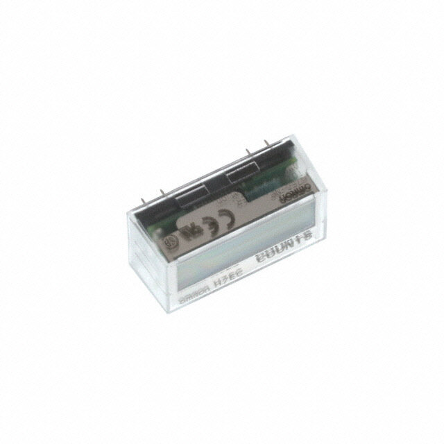
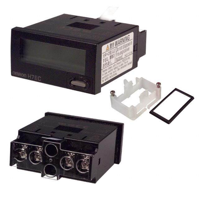
LC2H LC2H DIN HALF SIZE LCD COUNTER Counters Features 1. 8.7 mm .343 inch Character Height 6. Screw Terminals Designed for (previously 7 mm) Safety Easy-to-read character height increased Built in finger protection. from 7 mm to 8.7 mm .276 inch to .343 7. Panel Covers Replacable inch. (Standard color is ash gray.) Panel mounting type Change the panel design by replacing One-touch installation type 8.7mm with a black panel cover. .343inch 8. Conforms to IP66 Protective Construction (Only installation frame 2. Plenty of Digits type.) (Front panel surface) 9. Input Methods 1) Non-voltage input method 2) Voltage input method 8 digits Panel mounting type 3) Free voltage input method Installation frame type 3. Counting Speed Switchable 10. Backlight Type Added to Series between 2 kHz and 30 Hz and Now 2-color Switchable (green/ 4. Panel Mounting Type Features red) 2 Installation Methods Easy viewing even in dark places and Comes with very easy one-touch switchable between green and red installation type and also installation (Voltage input type). PC board mounting type frame type that uses the bracket on the 11. Compliant with UL, c-UL and CE. timer/counter. Choose a method that suits the application. 5. Battery Replacement Easy on Environment To replace battery simply remove body for the one-touch installation type, and remove battery lid for the installation frame type. Product chart Type Standard type Backlight type Voltage input type Free voltage input type Voltage input type Installation type Non-voltage input type (4.5 to 30 V DC) (24 to 240 V AC/DC) (4.5 to 30 V DC) Panel One-touch installation type (cid:1) (cid:1) (cid:1) (cid:1) mounting type Installation frame type (cid:1) (cid:1) (cid:1) (cid:1) PC board mounting type (cid:1) — — — Product types 1. Panel mounting type 1) One-touch installation type 1 Standard type No. digits Counting speed Front reset Input method Part No. Non-voltage input type LC2H-FE-2KK 2 kHz/30 Hz switchable 8 digits Yes Voltage input type (4.5 to 30 V DC) LC2H-FE-DL-2KK 30 Hz Free voltage input type (24 to 240 V AC/DC) LC2H-FE-FV-30 Note) Please ask us about types without front resetting. 2 Backlight type No. digits Counting speed Front reset Input method Part No. 8 digits 2 kHz/30 Hz switchable Yes Voltage input type (4.5 to 30 V DC) LC2H-FE-DL-2KK-B 98 CTi Automation - Phone: 800.894.0412 - Fax: 208.368.0415 - Web: www.ctiautomation.net - Email: info@ctiautomation.net
LC2H 2) Installation frame type 1 Standard type No. digits Counting speed Front reset Input method Part No. Non-voltage input type LC2H-F-2KK 2 kHz/30 Hz switchable 8 digits Yes Voltage input type (4.5 to 30 V DC) LC2H-F-DL-2KK 30 Hz Free voltage input type (24 to 240 V AC/DC) LC2H-F-FV-30 Note) Please ask us about types without front resetting. 2 Backlight type No. digits Counting speed Front reset Input method Part No. 8 digits 2 kHz/30 Hz switchable Yes Voltage input type (4.5 to 30 V DC) LC2H-F-DL-2KK-B 2. PC board mounting type No. digits Counting speed Front reset Input method Part No. 2 kHz LC2H-C-2K-N 8 digits No Non-voltage input type 30 Hz LC2H-C-30-N Specifications 1. Panel mounting type Type Standard type Backlight type Standard type Item Non-voltage input Voltage input Free voltage type No. digits 8 digits External power supply Not required (built-in battery) Max. counting speed 2 kHz/30 Hz (Switchable by switch) 30 Hz (Note 2) Min. input signal width 0.25 ms/16.7 ms (Switchable by switch) 16.7 ms (ON: OFF = 1:1) High level: Non-voltage input using High level: 4.5 to 30 V DC 24 to 240 V AC/DC Input method (signal) contacts or open collector Low level: 0 to 2 V DC Low level: Count connection 0 to 2.4 V AC/DC input When shorted: Input impedance Max. 10 kΩ Approx. 4.7 kΩ — When open: Max. 750 kΩ Residual voltage Max. 0.5 V — — Min. input signal width 200 ms Non-voltage input using Non-voltage input using High level: 4.5 to 30 V DC Input method (signal) contacts or open collector contacts or open collector Low level: 0 to 2 V DC connection connection Reset input When shorted: When shorted: Input impedance Max. 10 kΩ Appox. 4.7 kΩ Max. 10 kΩ When open: When open: Max. 750 kΩ Max. 750 kΩ Residual voltage Max 0.5 V — Max. 0.5 V 7-segment LCD Display method 7-segment LCD 7-segment LCD With green/red backlight Between charged and Breakdown voltage (initial) Between charged and uncharged parts: 1,000 V AC for 1 minute. uncharged parts: 2,000 V AC for 1 minute. Insulation resistance (initial) Min. 100 MΩ (measured at 500 V DC) Measurement location same as for break down voltage. Backlight power — 24 V DC (±10%) — Protective construction (Note 3) IEC Standard IP66 (only panel front: when using rubber gasket) Accessories (Note 3) Rubber gasket, mounting bracket Battery life 7 years (at 25°C 77°F) Note 1 6 years (at 25°C 77°F) Notes)1.The value given for battery life is calculated based on continuous operation (count input signal ON/OFF = 1:1), therefore, this value is not guaranteed. Also, battery life is decreased 30% when operation is continuous with 2 kHz count inputting in 2 kHz mode. 2.Operation is at 25 Hz when using 24 V AC. 3.Only for installation frame type. 99 CTi Automation - Phone: 800.894.0412 - Fax: 208.368.0415 - Web: www.ctiautomation.net - Email: info@ctiautomation.net
LC2H 2. PC board mounting type Type PC board mounting type Item Input method Non DC voltage input No. digits 8 digits Rated operation voltage 3 V DC Allowable operation voltage range 2.7 to 3.3 V DC Current consumption Max. 30 µA (max. 250 µA during reset input) Max. counting speed 2 kHz 30 Hz Min. input signal width 0.25 ms 16.7 ms (ON: OFF = 1:1) Count Input method Non-voltage input using contacts or open collector connection input When shorted: Max. 10 kΩ Input impedance When open: Max. 750 kΩ Residual voltage Max. 0.5 V Min. input signal width 10 ms Input method Non-voltage input using contacts or open collector connection Reset input Input impedance WWhheenn sohpoernte: dM: aMxa. x7. 5100 kkΩΩ Residual power Max. 0.5 V Break down voltage (initial) Between charged and uncharged parts: 1,000 V AC for 1 minute. Insulation resistance (initial) Min. 100 MΩ (measured at 500 V DC) Measurement location same as for break down voltage. 3. Common Type Panel mounting/PC board mounting types Item Functional 10 to 55 Hz (1 cycle/min.), single amplitude: 0.15 mm .006 inch (10 min. on 3 axes) Vibration resistance Destructive 10 to 55 Hz (1 cycle/min.), single amplitude: 0.375 mm .015 inch (1 hr. on 3 axes) Functional Min. 98 m/s2 (4 times on 3 axes) Shock resistance Destructive Min. 294 m/s2 (5 times on 3 axes) Operation temperature –10 to +55°C +14 to +131°F (without frost or dew) Storage temperature –25 to +65°C –13 to +149°F (without frost or dew) Ambient humidity 35 to 85% RH (non-condensing) Applicable standard Safety standard EN61010-1 Pollution Degree 2/Overvoltage Category III (EMI)EN61000-6-4 Radiation interference electric field strength EN55011 Group1 ClassA Noise terminal voltage EN55011 Group1 ClassA (EMS)EN61000-6-2 Static discharge immunity EN61000-4-2 4 kV contact 8 kV air EMC RF electromagnetic field immunity EN61000-4-3 10 V/m AM modulation (80 MHz to 1 GHz) 10 V/m pulse modulation (895 MHz to 905 MHz) EFT/B immunity EN61000-4-4 2 kV (power supply line) Conductivity noise immunity EN61000-4-6 10 V/m AM modulation (0.15 MHz to 80 MHz) Power frequency magnetic field immunity EN61000-4-8 30 A/m (50 Hz) 100 CTi Automation - Phone: 800.894.0412 - Fax: 208.368.0415 - Web: www.ctiautomation.net - Email: info@ctiautomation.net
LC2H Part names 1. Front reset button COUNTER Count speed switch This button resets the count value. It does not work when the lock switch is ON. Be aware that battery life will RESET decrease if this switch is used frequently. LC2H 2. Lock switch (Refer to chart on right.) Front reset button Disable the front reset button. Lock switch Note)Turn ON at the LCD side (reset disabled) and OFF at the terminal block side (reset enabled). 3. Count speed switch (Refer to chart on right.) Use this switch to switch the count speed Non-voltage input/voltage input Free voltage input between 30 Hz and 2 kHz. (On the non- voltage and voltage input types, 30 Hz is (Terminal block side) OFF❇ on the LCD side and 2 kHz is on the Lock switch terminal block side. Fixed at 30 Hz for (Unit display 1) free voltage input type.) (LCD side) ON Note)You must press the front reset button when you change the count speed switch setting. Confirm, however, that the Lock Switch is OFF (Terminal block side) 2k Hz (front switches operable). Count speed — switch (Unit display 2) (LCD side) 30Hz❇ (Fixed at 30 Hz) Notes)1.❇Default setting when shipped. 2.Make the switch setting before installing to panel. Dimensions mm inch General tolerance: ±1.0 ±.039 1. Panel mounting type • External dimensions • Panel installation diagram 1) One-touch installation type 44.8 1.764 Panel (1 to 4.5mm 25.41.442 .t0h3ic9k ntoe s.1s)77inch Rubber spacer Note)When installing to a 4.5 mm .177 inch thick panel, remove the rubber spacer first. When installing the one-touch installation type model, make sure that the installation spring does not pinch the rubber gasket. 10.4 (44) 5 48 .409 (1.732) .197 1.890 To prevent the installation spring COUNTER from pinching the rubber gasket: 1. Set the rubber gasket on both 22 24 .866 .945 RESET ends of the installation spring LC2H (left and right). 7 2. Confirm that the installation .276 Reset button spring is not pinching the rubber gasket, and then insert and fix the installation spring in place from the rear of the timer unit. 101 CTi Automation - Phone: 800.894.0412 - Fax: 208.368.0415 - Web: www.ctiautomation.net - Email: info@ctiautomation.net
LC2H 2) Installation frame type • Panel mounting diagram 44.8 Mounting screws Mounting frame 1.764 (found on mounting frame) ATH3803 (included) 54.4 37 2.142 1.457 Rubber gasket Panel ATH3804 (included) (1 to 4.5mm .039 to .177inch thickness) 10.4 44 5 48 .409 1.732 .197 1.890 COUNTER 22 24 .866 .945 RESET LC2H 7 .276 Reset button • Panel cut-out dimensions • For connected installation (sealed installation) The standard panel cut-out is shown below. (Only installation frame type.) Use the mounting frame (ATH3803) and the rubber packing (ATH3804). (Only installation frame type.) 2.827.24++00.00.520 A 60 min. A=A(1=.(84980××nn-2-..059)+810.)0+.0039 2.362 min. 1.74752++00.00.520 Notes)1. Suitable installation panel thickness is 1 to 4.5 mm .039 to .177 inch. 2. Waterproofing will be lost when installing repeatedly (sealed installation). 2.827.24++00.00.520 • Terminal layout and wiring diagrams 1) Standard type Non voltage input type Voltage input type Free voltage input type Count input Reset input Count input Reset input Count input Reset input +V +V 1 2 3 4 1 2 3 4 or 1 2 3 4 0V 0V W-R are connected internally. 2) Backlight type Voltage input type Backlight <When green> <When red> 0V +V Count input Reset input +V +V 5 5 5 1 2 3 4 1 2 3 4 1 2 3 4 6 6 6 0V 0V 0V +V 102 CTi Automation - Phone: 800.894.0412 - Fax: 208.368.0415 - Web: www.ctiautomation.net - Email: info@ctiautomation.net
LC2H 2. PC board mounting type General tolerance: ±1.0 ±.039 mm inch • External dimensions PC board pattern (BOTTOM VIEW) 33.02±0.3 .52.0008±±.00.132 1.300±.012 5.2.0080±±0.0.312 2.54 Mounting area 0.6±0.1 .100 1.9 .024±.004 DIP switch × 8 .075 2.54 .133.03±±.00.31 2 8-0.8 di.a1.00 1.56.0204 C28o npnine cDtiIoPn t esromckineatsl 8-.031 dia. 1.9 14.37.049 1.678.31 0.0.520±0±.3.012 5.2.0080 5.2.1094.075 5.19 5.08 .204 .200 19 15.24±0.3 33.02 .748 .600±.012 1.300 COUNTER LC2H General tolerance: ±0.1 ±.004 0.3±0.1 .012±.004 • Terminal layout and wiring diagrams Note: The AXS212811K is recommended as a compatible connection socket. 15 17 26 28 Count input Reset input 14 12 3 1 Q-E, }-w, e-t and S-F are connected internally. An external power supply is required. Input method 1. Standard type Non-voltage input type Panel mounting type PC board mounting type Transistor input Transistor input Contact input Contact input NPN transistor NPN transistor Cinopuuntt 1 2 3 4 Rinepsuett Cinopuuntt 1 2 3 4 Rinepsuett Cinopuuntt 1154 1127 236 218 Rinepsuett Cinopuuntt 1154 1127 236 218 Rinepsuett 0V 0V (W and R are connected internally.) (W and R are connected internally.) 3V DC 3V DC Notes)1.When using contact input, since current flow is small from terminals 1 and 3 on the panel mounting type and terminals e to t and S to F on the PC board mounting type, please use relays and switches with high contact reliability. 2.When using transistor input, use the following as a guide for which transistors (Tr) to use for inputting. (Collector withstand voltage Q 50 V, leakage current < 1 µA) Voltage input type Transistor input Free voltage input type Contact input NPN transistor PNP transistor +V +V +V +V Count Reset input 1 2 3 4 input Cinopuuntt 1 2 3 4 Rinepsuett Cinopuuntt 1 2 3 4 Rinepsuett Count input or or 1 2 3 4 or Reset input Notes)1.2 and 4. (The input and reset circuits are functionally insulated.) 2.When using transistor (Tr) input, use the right as a guide. (Collector withstand voltage Q 50 V, leakage current < 1 µA) 3.Be aware that the application of voltage that exceeds the voltage range of the H level to the count input terminal, and the application of voltage to the reset input terminal, can cause damage to the internal elements. 103 CTi Automation - Phone: 800.894.0412 - Fax: 208.368.0415 - Web: www.ctiautomation.net - Email: info@ctiautomation.net
LC2H 2. Backlight type Voltage input type Transistor input Backlight connection Contact input NPN transistor PNP transistor Green Red +V +V +V +V Count Reset 24V DC input input 1 2 56 3 4 Cinopuuntt 1 2 56 3 4 Rinepsuett Cinopuuntt 1 2 56 3 4 Rinepsuett 1 2 56 3 4 1 2 56 3 4 0V 0V 24V DC Notes)1.Do not reverse the polarities when connecting the DC voltage for the backlight. 2.2 and 4. (The input and reset circuits are functionally insulated.) 3.When using transistor (Tr) input, use the right as a guide. (Collector withstand voltage Q 50 V, leakage current < 1 µA) 4.Be aware that the application of voltage that exceeds the voltage range of the H level to the count input terminal, and the application of voltage to the reset input terminal, can cause damage to the internal elements. Explanation of operation 1. Counting takes place when the count input signal is ON. Count input 2. Counting resumes again when the count value reaches 99999999 (full scale ❇ Reset input value) and then returns to “0” with a new count input. Count value 0 1 99999999 0 1 0 1 3. No measurement takes place when a Note) ❇Count becomes “1” when the reset input is turned OFF while the count signal is being input. reset is input. 1) When reset is ON, resetting takes place and the count becomes “0”. 2) Press the front reset button when you want to reset manually (only panel installation type). Note)Be aware that battery life will decrease if the count input or reset input are left ON. 104 CTi Automation - Phone: 800.894.0412 - Fax: 208.368.0415 - Web: www.ctiautomation.net - Email: info@ctiautomation.net
LC2H Cautions for use 1. Non-voltage input type 2) For external resetting use H level Voltage input type For both panel mounting and PC (application of 4.5 to 30 V DC) between +V +V board mounting types reset terminals 3 and 4 of the rear R Tr 1) Never apply voltage to the non-voltage terminals. In this case, connect + to 3 4 3 4 3 4 or 3 4 input type. This will damage the internal terminal 3 and – to terminal 4. This is elements. Also, since there is a possibility the valid polarity; therefore, the counter Note)Make sure that H (reset ON) level is at least 4.5 of erroneous operation, do not connect in will not work if reversed. V. parallel the inputs of a non-voltage input 3) When wiring, try to keep all the input 5. Backlight luminance type and another counter from a single lines to the count and reset inputs as To prevent varying luminance among input signal. short as possible and avoid running them backlights when using multiple Backlight 2) Since the current flow is very small together with high voltage and power types, please use the same backlight from the count input and reset input transmission lines or in a power conduit. power supply. terminals (1 and 3 on the panel Also, malfunctions might occur if the mounting type and terminals e to t and floating capacitance of these wires S to F on the PC board mounting type) exceeds 500 pF (10 m 32.808 ft. for 24V DC 2 5 2 5 2 6 2 6 24V DC please use relays and switches with high parallel wires of 2 mm2). Green Red contact reliability. 3. Free voltage input type 6. Environment for use 3) When inputting with an open collector 1) Use count input terminals 1 and 2 for 1) Ambient conditions of a transistor, use a transistor for small free voltage input and reset terminals 3 • Overvoltage category II, pollution level 2 signals in which ICBO is 1 µA or less and and 4 for non-voltage input. • Indoor use always input with no voltage. 2) Be aware that the application of • Acceptable temperature and humidity 4) When wiring, try to keep all the input voltage that exceeds the voltage range of range: –10 to +55°C, 35 to 85%RH (with lines to the count and reset inputs as the H level to the count input terminal, no condensation at 20°C) short as possible and avoid running them and the application of voltage to the reset • Under 2000 m elevation together with high voltage and power input terminal, can cause damage to the 2) Use the main unit in a location that transmission lines or in a power conduit. internal elements. matches the following conditions. Also, malfunctions might occur if the 3) Since the current flow is very small • There is minimal dust and no corrosive floating capacitance of these wires from reset input terminal 3, please use gas. exceeds 500 pF (10 m 32.808 ft. for relays and switches with high contact • There is no combustible or explosive parallel wires of 2 mm2). When using 2 reliability. gas. kHz mode, use with a wiring floating 4) When inputting a reset with an open • There is no mechanical vibration or capacitance of 120 pF (3 m 9.843 ft. for collector of a transistor, use a transistor impacts. parallel wires of 2 mm2). In particular, for small signals in which ICBO is 1 µA or • There is no exposure to direct sunlight. when using shielded wiring, be careful of less and always input with no voltage. • Located away from large-volume the capacitance between wires. 5) To reset externally, short reset input electromagnetic switches and power PC board mounting type terminals 3 and 4 on the rear. lines with large electrical currents. 1) For external power supply use 6) Input uses a high impedance circuit; 3) Connect a breaker that conforms to manganese dioxide or lithium batteries therefore, erroneous operation may occur EN60947-1 or EN60947-3 to the voltage (CR type: 3V). if the influence of induction voltage is input section. 2) Always reset after external power is present. If you plan to use wiring for the 4) Applied voltage should be protected applied and confirm that the display input signal that is 10 m or longer (wire with an overcurrent protection device reads “0”. capacitance 120 pF/m at normal (example: T 1A, 250 V AC time lag fuse) 3) Make the wiring from the battery to the temperature), we recommend the use of that conforms to the EN/IEC standards. counter unit as short as absolutely a CR filter or the connection of a bleeder (Free voltage input type) possible. Also, be careful of polarity. resistor. 4) Calculate battery life with the following 4. How to reset multiple panel formula. mounting type counters all at once t = A/I (input is the same for count) t: battery life [h] Non-voltage input type I: LC2H current consumption [mA] A: battery capacity until minimum D D D Tr operation voltage is reached [mAh] 3 4 3 4 3 4 or 5) Hand solder to the lead terminal. Do not dip solder. With the tip of the Notes)1.Use the following as a guide for choosing soldering iron at 300°C 572°F perform transistors used for input (Tr). Leakage current < 1 µA soldering within 3 seconds (for 30 to 60 2.Use as small a diode (D) as possible in the W soldering iron). forward voltage so that the voltage between terminals 3 and 4 during reset input meets 2. Voltage input type the standard value (0.5 V). 1) Be aware that applying more than 30 V ( At IF = 20 µA, forward voltage 0.1 and DC to count input terminals 1 and 2, higher.) and reset input terminals 3 and 4 will cause damage to the internal elements. 105 CTi Automation - Phone: 800.894.0412 - Fax: 208.368.0415 - Web: www.ctiautomation.net - Email: info@ctiautomation.net
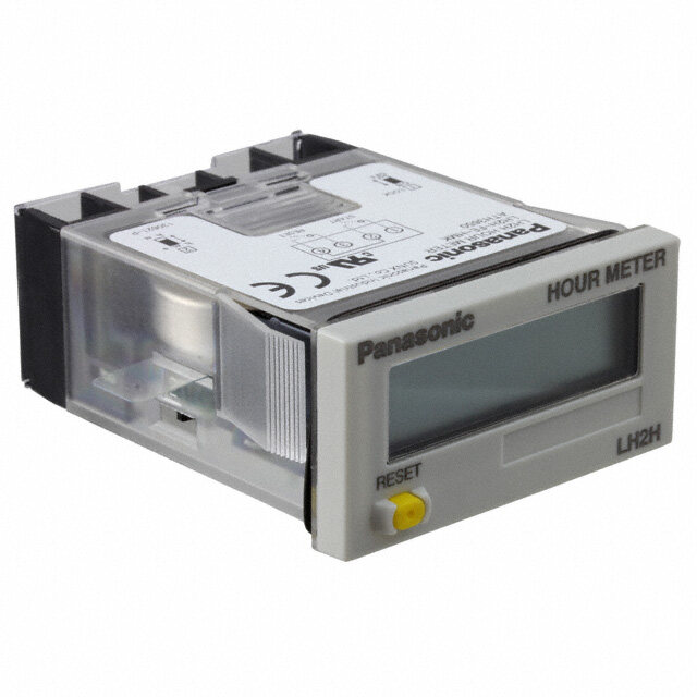
LC2H LC2H PRESET COUNTER Counter Features 1. Preset function equipped in half 3. 8.7 mm 0.343 inch Character Height size (24 × 48 mm 0.945 × 1.890 inch). (previously 7 mm 0.276 inch) 2. Display has backlight for instant Easy-to read character height increased recognition. from 7 mm to 8.7 mm 0.276 inch to 0.343 inch. Counting Counting up Red or (Green) 8.7mm (backlight) .343inch Green or (Red) 4. Plenty of Digits (backlight) (Lit or Flashing) Red or (Green) 8 digits (backlight) Green or Red can 5. Counting Speed Switchable be selected at setup. between 30 Hz and 5 kHz 6. Conforms to IP66 Protective (Lit or Flashing) Construction (Front panel surface) Lit or Flashing can Weatherproofing supported by using be selected at setup. optional mounting frame and rubber gasket 7. Includes reassuring lock mode and lock switch to prevent erroneous operation. 8. Screw terminals are constructed to protect fingers to ensure safety. 9. Compliant with UL, c-UL and CE. Product types No. digits Counting speed Output mode Output Operating voltage Part No. • Maintain output/hold count 30 Hz/5 kHz • Maintain output/over count 8 digits Transistor (1a) 24 V DC LC2HP-FEW-B-DC24V switchable • One shot/over count • One shot/recount Mounting frame ATH3803 Options Use for waterproofing (front panel surface) Rubber gasket ATH3804 Note:Mounting frame and rubber gasket are not included. 106 CTi Automation - Phone: 800.894.0412 - Fax: 208.368.0415 - Web: www.ctiautomation.net - Email: info@ctiautomation.net
LC2H Specifications Item Descriptions Rated operating voltage 24 V DC Rated power consumption Max. 1.5 W Rated control capacity 100 mA 30 V DC Input mode Addition/Subtraction (selectable by front switch) Max. counting speed 30 Hz/5 kHz (selectable by slide switch on side) Min. input signal width: 16.7 ms at 30 Hz/0.1 ms at 5 kHz, Counting input ON time : OFF time = 1 : 1 Reset input Min. input signal width: Min. 30 ms • Non-voltage input using contacts or open-collector connection Rating Input signal • Input impedance; when shorted: Max. 1 kΩ, when open: Min. 100 kΩ • Residual voltage: Max. 2 V • Maintain output/hold count • Maintain output/over count Output mode • One shot/over count • One shot/recount (Selectable by front switch) 7-segment LCD Display method (Switch between red and green for backlight, and between lit and flashing for count up.) –9999999 to 99999999 (–7 digits to +8 digits) Digit (0 to 99999999 for preset value) Memory EEP-ROM (Overwriting times: 105 operations or more) Contact arrangement 1 Form A (Open collector) Electrical life (contact) 107 operations (at rated control voltage) Allowable operating voltage range 85 to 110% of rated operating voltage Electrical Break down voltage (Initial value) Between input and output: 1,500 V AC, for 1 min. Insulation resistance (Initial value) Between input and output: 100 MΩ (at 500 V DC) Functional vibration resistance 10 to 55 Hz (1 cycle/min), Single amplitude: 0.15 mm (10 min. on 3 axes) Destructive vibration resistance 10 to 55 Hz (1 cycle/min), Single amplitude: 0.375 mm (1 hr. on 3 axes) Mechanical Functional shock resistance Min. 98 m/s2 (4 times on 3 axes) Destructive shock resistance Min. 294 m/s2 (5 times on 3 axes) Operation temperature –10 to 55°C +14 to +131°F (without frost or dew) Operating Storage temperature –25 to +65°C –13 to +149°F (without frost or dew) conditions Ambient humidity 30 to 85% RH (at 25°C 77°F, non-condensing) Protective construction IP66 (front panel with mounting bracket and rubber gasket) * The factory default preset value is set to 1000000. Applicable standard (EMI)EN61000-6-4 Radiation interference electric field strength EN55011 Group1 ClassA Noise terminal voltage EN55011 Group1 ClassA (EMS)EN61000-6-2 Static discharge immunity EN61000-4-2 4 kV contact 8 kV air EMC RF electromagnetic field immunity EN61000-4-3 10 V/m AM modulation (80 MHz to 1 GHz) 10 V/m pulse modulation (895 MHz to 905 MHz) EFT/B immunity EN61000-4-4 2 kV (power supply line) 1 kV (signal line) Conductivity noise immunity EN61000-4-6 10 V/m AM modulation (0.15 MHz to 80 MHz) Power frequency magnetic field immunity EN61000-4-8 30 A/m (50 Hz) 107 CTi Automation - Phone: 800.894.0412 - Fax: 208.368.0415 - Web: www.ctiautomation.net - Email: info@ctiautomation.net
LC2H Part names 1. Front reset key 5 This key resets the count value. It does not work when the lock switch is ON. COUNTER 2. Mode key Use to switch between each mode. 3. Setting key RESET MODE SET LC2H Used to set digits of preset values or set 1 2 3 4 6 each mode. 4. Set key Use to set preset values or to switch between modes. 5. Lock switch ❇: Default setting when shipped. Disable the operation of the front panel reset key and the mode key. With the lock (Terminal block side) OFF❇ switch on, is displayed for about Lock switch two seconds when the reset key or mode 5 (unit display 1) switch is operated. (LCD side) ON 6. Count speed switch Use this switch to switch the count speed between 30 Hz and 5 kHz. (Terminal block side) 5kHz Count speed switch 6 (unit display 2) (LCD side) 30Hz❇ Notes:1.Make the switch setting before installing to panel. 2.Please turn the power off if you change the setting of the count speed switch when the power is on. The setting will become valid when the power is turned back on. Dimensions mm inch General tolerance: ±1.0 ±.039 • External dimensions 44.8 1.764 When installing the one-touch installation type model, make sure that the installation spring does not pinch the rubber gasket. To prevent the installation spring from pinching the rubber gasket: 54.4 2.142 1. Set the rubber gasket on both ends of the installation spring (left and right). 2. Confirm that the installation spring is not pinching the rubber 10.4 44 5 48 .409 1.732 .197 1.890 gasket, and then insert and fix the COUNTER installation spring in place from the 22 24 rear of the timer unit. .866 .945 RESET MODE SET LC2H 7 .276 • Panel cut out dimensions • When installing repeatedly (sealed installation) The standard panel cut out is shown below. (Only installation frame type) Use the mounting bracket (ATH3803) and the rubber gasket (ATH3804). (Only installation frame type) 2.827.24++00.00.520 A 60 min. A=A(1=.(84980××nn-2-..059)+810.)0+.0039 2.362 min. 1.74752++00.00.520 Notes:1.Suitable installation panel thickness is 1 to 4.5 mm 0.39 to 0.177 inch. 2.Waterproofing will be lost when installing repeatedly (sealed installation). 2.827.24++00.00.520 108 CTi Automation - Phone: 800.894.0412 - Fax: 208.368.0415 - Web: www.ctiautomation.net - Email: info@ctiautomation.net
LC2H How to set 1. Preset value setting mode 2) The display reads “Un-Lock” after 4) The backlight changes from flashing This is the mode for setting preset values. entering the lock mode (initial setting). green to flashing red to lit green and to lit red with each press of the setting key. Display after entering lock mode 5) Pressing the front panel reset key sets (Example showing “Un-Lock”.) Press the MODE key. Set the digit. Set the value. the current backlight color and returns 3) Pressing the setting key changes the you to regular operation mode. 1) Pressing the MODE key takes you to display between “ Lock” and “Un- Note:You will not be returned to regular operation the preset value setting mode. lock”. mode if you do not press the front panel reset key. Sample display in preset value 4. Input setting mode setting mode (Example showing “ Lock”.) (when preset value is 1000) This is the mode for setting addition or 2) Pressing the setting key moves the 4) Pressing the front panel reset key sets subtraction. flashing digit left by one. Following the the content displayed and returns you to + highest digit it returns to the lowest digit regular operation mode. Press the SET key while pressing Addition Subtraction and each time the digit setting key is Note:You will not be returned to regular operation the MODE key. mode if you do not press the front panel reset pressed it moves one to the left. key. 1) Pressing the SET key three times 3) Pressing the set key increases the 5) When the lock mode display reads while holding down the MODE key takes value by one. (After 9 it returns to 0 and “ Lock”, you will not be able to move you to the input setting mode. then changes to 1, 2, 3, etc.) to the backlight setting mode, the input 2) The display after entering the input 4) Pressing the front panel reset key sets setting mode, or the output setting mode. setting mode reads “ UP” (initial the displayed preset value and returns 3. Backlight setting mode setting). you to the regular operation mode. This is the mode for setting the backlight 5) In the preset value setting mode if you during count up. Display after entering input setting mode do not operate the digit setting key or the (Example showing “UP”) set key for ten seconds or more you will + 3) Pressing the setting key changes the be returned to regular operation. In this Press the SET key while pressing Lit red Flashes green the MODE key. Lit green Flashes red display to “dn” (subtraction) and pressing case the preset value will not change. it again changes it to “UP” (addition). The 2. Lock mode 1) Pressing the SET key two times while display alternates between “dn” and “UP”. This mode prohibits everything except holding down the MODE key takes you to the preset value setting mode. the backlight setting mode. (Example showing “dn”) 2) The display in the backlight setting + mode reads “ LEd” 4) Pressing the front panel reset key sets Press the SET key while pressing Un-Lock Lock the content displayed and returns you to the MODE key. Display after entering regular operation mode. the backlight setting mode. 1) Pressing the set key while holding Note:You will not be returned to regular operation down the mode key takes you to the lock 3) The LED backlight will be red (initial mode if you do not press the front panel reset mode. setting). key. 109 CTi Automation - Phone: 800.894.0412 - Fax: 208.368.0415 - Web: www.ctiautomation.net - Email: info@ctiautomation.net
LC2H 5. Output setting mode This sets the operation mode. 2) Lock mode + + Press the SET key while pressing HOLD-A HOLD-B Press the SET key while pressing Un-Lock Lock the MODE key. SHOT-B SHOT-A the MODE key. 1) Pressing the SET key four times while When the lock is set, you cannot enter modes other than backlight setting mode. holding down the MODE key takes you to 3) Backlight setting mode the output setting mode. + 2) The display reads “HoLd-A” (initial Press the SET key while pressing Lit red Flashes green the MODE key. Lit green Flashes red setting) after entering the output setting mode. Front panel reset key 4) Input setting mode + Press the SET key while pressing Addition Subtraction Regular operation mode 3) Pressing the setting key causes the the MODE key. display to change as follows: HOLD-B (Output maintain/over count I) 5) Output setting mode + Press the SET key while pressing HOLD-A HOLD-B the MODE key. SHOT-B SHOT-A SHOT-A (One shot/over count) Mode changes as follows by pressing the SET key while holding down the MODE key. Lock mode Backlight setting mode Output setting mode Input setting mode SHOT-B (One shot/recount I) Please be aware that after doing a front Preset Output Count value panel reset key and returning to regular value change operation mode, the preset values, count Lock × × × mode value and output will be as shown in this HOLD-A (Output maintain/hold count) table. Bseatctiknlgig ht × × × 4) Pressing the front panel reset key sets mode the display content and returns you to Input Addition: “0” regular operation mode. setting × Subtraction: ON➝OFF Note:You will not be returned to regular operation mode “Preset value” mode if you do not press the front panel reset Output Addition: “0” key. setting × Subtraction: ON➝OFF mode “Preset value” Note: “×” sign: No change Changing the preset value 1. It is possible to change the preset 2) Suppose that the counter is preset to 1) Addition (up-count) input when value even during counting. However, count down. Whether a preset count counting is set to the addition direction, be aware of the following points. down value is smaller or larger than the counting will continue until full scale is 1) If the preset value is changed to less count value, the counter counts down to reached, return to zero, and then than the count value with counting set to “0 (zero)”. complete count-up. the addition direction, counting will 2. If the preset value is changed to “0”, 2) Subtraction (down-count) input when continue until it reaches full scale, returns the counter will not complete count- counting is set to the subtraction direction, to zero, and then reaches the new preset up. It starts counting up when the counting will continue until full scale value. If the preset value is changed to a counting value comes to “0 (zero)” “–9999999” is reached, and then the value above the count value, counting will again. display will change to “ ”. continue until the count value reaches the new preset value. Compliance with the CE marking • EMC Directive (89/336/EEC) The LC2H Preset Counter conforms to the EMC Directive as a simple counter. Applicable standards: EN61000-6-4, EN61000-6-2 110 CTi Automation - Phone: 800.894.0412 - Fax: 208.368.0415 - Web: www.ctiautomation.net - Email: info@ctiautomation.net
LC2H Operation mode Output mode Operation Example when input mode is either addition or Subject:ubtraction Output control is maintained after count-up completion and until resetting. Output OFF ON Output maintain/ During that time, the count display does not Counting able/unable Able Unable hold count change from that at count-up completion. Addition 0 1 2 3 4 n–1 n HOLD-A Subtraction n n–1 n–2 n–3 n–4 1 0 n: Preset value Output control is maintained after count-up completion and until resetting. However, Output OFF ON Output maintain/ counting is possible despite completion of Counting able/unable Able over count I count-up. Addition 0 1 2 3 n–2 n–1 n n+1 n+2 n+3 HOLD-B Subtraction n n–1 n–2 n–3 2 1 0 –1 –2 –3 n: Preset value Output control is maintained after count-up One shot pulse width: approx. 1 sec. completion for a fixed time (approx. 1 sec.). Counting is possible despite completion of Output OFF ON One shot/ count-up. Counting able/unable Able over count SHOT-A Addition 0 1 2 3 n–2 n–1 n n+1 n+2 n+3 Subtraction n n–1 n–2 n–3 2 1 0 –1 –2 –3 n: Preset value Output control is maintained after count-up One shot pulse width: approx. 1 sec. completion for a fixed time (approx. 1 sec.). Counting is possible despite completion of Output OFF ON One shot/ count-up. However, reset occurs Counting able/unable Able recount I simultaneous with completion of count-up. SHOT-B While output is being maintained, restarting Addition 0 1 2 3 n–1 0 1 2 3 4 of the count is not possible. Subtraction n n–1 n–2 n–3 1 n n–1 n–2 n–3 n–4 n: Preset value 111 CTi Automation - Phone: 800.894.0412 - Fax: 208.368.0415 - Web: www.ctiautomation.net - Email: info@ctiautomation.net
LC2H Cautions for use 1. Input and output connection VCEO = Min. 20 V (3) Input wiring 1) Input connection IC = Min. 20 mA When wiring, use shielded wires or (1) Contact input ICBO = Max. 6 µA metallic wire tubes, and keep the wire Use highly reliable metal plated contacts. Also, use transistors with a residual lengths as short as possible. Since the contact’s bounce time leads voltage of less than 2 V when the 2) Output connection directly to error in the count value, use transistor is on. Since the transistor output of counter is contacts with as short a bounce time as * The short-circuit impedance should be less insulated from the internal circuitry by a possible. In general, select input to have than 1 kΩ. photo-coupler, it can be used as an NPN a maximum counting speed of 30 Hz. (When the impedance is 0 Ω, the current output or PNP (equal value) output. coming from the count input terminal is As NPN output approximately 5 mA and from the reset Count 5 Reset input 1 2 6 3 4 input input terminal is approximately 1.5 mA.) Load (2) Non-contact input (Transistor input) Abels om, othree tohpaenn 1-c0i0rc kuΩit .impedance should 1 2 56 3 4 Lsuopapdl’ys power Connect with an open collector. Use As PNP output transistors whose characteristics satisfy Count 5 Reset the criteria given below. input 1 2 6 3 4 input 1 2 56 3 4 Lsuopapdl’ys power Load 2. Self-diagnosis function 3. Terminal connection If a malfunction occurs, one of the following displays will appear. 1) When wiring the terminals, refer to the terminal layout and Output Restoration Preset values after wiring diagrams and be sure to perform the wiring properly Display Contents condition procedure restoration without errors. The preset value at An external power supply is required in order to run the main Err-00 Malfunctioning Enter front start-up before the unit. CPU reset key or CPU malfunction Power should be applied between OFF restart occurred. terminals (1) and (2). Terminal (1) acts 1 2 5 3 4 Err-01 Malfunctioning counter 0 as the positive connection and terminal 6 memory* (2) as the negative. * Includes the possibility that the EEP-ROM’s life has expired. Operating voltage 2) After turning the counter off, make sure that any resulting induced voltage or residual voltage is not applied to power supply terminals (1) through (2). (If the power supply wire is wired parallel to the high voltage wire or power wire, an induced voltage may be generated at the power supply terminal.) 3) Have the power supply voltage pass through a switch or relay so that it is applied at one time. 112 CTi Automation - Phone: 800.894.0412 - Fax: 208.368.0415 - Web: www.ctiautomation.net - Email: info@ctiautomation.net
LC2H PRECAUTIONS IN USING THE LC2H SERIES Cautions for use 1. Insulation sheet •LC2H preset counter 5. Cautions regarding battery Before using a panel mounting type, 1) The front plate will not be waterproof replacement please pull and remove the insulation when this product is installed on a panel. 1) Remove wiring before replacing the sheet from the side of the product in the To make the front plate waterproof, battery. You may be electrocuted if you direction of the arrow. please install the following. come into contact to a part where high In consideration that the product might be When using the waterproof type (IP66: voltage is applied. stored for long periods without being panel front only), install the counter to the 2) Make sure you are not carrying a static used, an insulation sheet is inserted front plate with mounting frame ATH3803 electric charge when replacing the before shipping. Remove the insulation (sold separately) and rubber gasket battery. sheet and press the front reset button. ATH3804 (sold separately). Be sure to 3) Battery replacement procedure •LC2H total counter (one-touch tighten using mounting screws. For LC2H total counter (one-touch installation type) installation type) Mounting frame (ATH3803) (1)Remove the up/down hook of the case using a tool. (2)Pull the unit away from the case. (3)Remove the battery from the side of the unit. Do not touch the display or other parts. (4)Before inserting wipe clean the Rubber gasket (ATH3804) surface of the new battery. Insulation sheet Reset button When installing the mounting frame (5)Insert the new battery with the “+” •LC2H total counter (installation and rubber gasket please remove the and “–” sides in the proper position. pre-attached o-ring. (6)After replacing the battery, return frame type) the unit to the case. Verify that the 2) Panel installation order hook of the case has properly (1)Remove o-ring. engaged. (2)Place rubber gasket. (7)Before using, press the reset button (3)Insert counter into panel. on the front. (4)Insert mounting frame from the rear. Tool (5)Secure with mounting screws (two locations) 1 Insulation sheet Reset button 3. Do not use in the following environments 2. Waterproof construction 1) In places where the temperature •LC2H total counter (installation 2 changes drastically. frame type) 2) In places where humidity is high and The operation part of the panel there is the possibility of dew. installation type (installation frame type) (When dew forms the display may vanish is constructed to prevent water from and other display errors may occur.) entering the unit and a rubber gasket is 4. Conditions of use 1 provided to prevent water from entering 1) Do not use on places where there is the gap between the unit and the panel flammable or corrosive gas, lots of dust, cutout. presence of oil, or where the unit might There must be sufficient pressure applied be subject to strong vibrations or shocks. to the rubber gasket to prevent water 2) Since the cover is made of from entering. polycarbonate resin, do not use in places Be sure to use the mounting reinforcement screws when installing the where the unit might come into contact 3 with or be exposed to environments that mounting frame (ATH3803). contain organic solvents such as methyl Note: The one-touch installation type is alcohol, benzene and thinner, or strong 6 not waterproof. alkali substances such as ammonia and Mounting frame caustic soda. (ATH3803) 7 113 CTi Automation - Phone: 800.894.0412 - Fax: 208.368.0415 - Web: www.ctiautomation.net - Email: info@ctiautomation.net
LC2H For LC2H total counter 6. Terminal connection (installation frame type) 1 Tighten the terminal screws with a torque (1)Remove the battery cover from the of 0.8 N·cm or less. case. (2)Remove the battery from the side of the case. The battery will come loose if you put the battery side face down and lightly shake the unit. (3)Before inserting wipe clean the surface of the new battery. (4)Insert the new battery with the “+” and “–” sides in the proper position. (5)After replacing the battery, return 2 the battery cover to the case. Verify “+” side that the hook of the battery cover is properly engaged. (6)Before using press the reset button 5 on the front. “−” side 6 Options 1. Accessories (for LC2H total 2. Lithium battery (3 V) 3. Installation parts counter) Mounting frame Panel cover (black) JACPP3ARaVN2n4a7so7nic (toStuailt acboluen ftoerr iannstda lLlaCti2oHn fprraemseet t ycpoeu nLtCer2)H COUNTER Part No.: ATH3802 Packaged with the LC2H (excluding the RESET PC board mounting type). LC2H Part No.: AEL3801 Warning You can change the design of the front panel by replacing it with this black panel • Make sure the “+” and “−” polarities are Part No.: ATH3803 positioned correctly. cover. The counter comes with an ash Packaged with the mounting bracket type • Do not throw the old battery into a fire, gray panel cover as standard. short circuit it, take it apart, or allow it to LC2H total counter Note:No panel cover accessory (black) is available come into contact with heat. for the LC2H preset counter. • The battery is not rechargeable. Rubber gasket (Suitable for installation bracket type LC2H total counter and LC2H preset counter) Part No.: ATH3804 Packaged with the mounting bracket type LC2H total counter 114 CTi Automation - Phone: 800.894.0412 - Fax: 208.368.0415 - Web: www.ctiautomation.net - Email: info@ctiautomation.net
COUNTERS SELECTOR CHART Contact Contact Open output output collector (1 Form C) (1 Form A) output Classification Electronic counters Name of product LC2H Counter LC2H Counter LC4H/-L Counter LC4H-S Counter LC4H-W Counter Type Total counter Preset counter Preset counter Preset counter Preset counter UP, DOWN, and DIR UP, DOWN, and DIR UP, DOWN, and DIR Input mode/Input method UP type UP, DOWN type (multi-mode) 2 modes (multi-mode)/DIP switch (multi-mode)/DIP switch selectable/DIP switch Flush mounting type Appearance PC board mounting type 4-digit 6-digit 4-digit 6-digit display display display display AEL3 AEL3 8.7 mm tall 8-digit display 8.7 mm tall 8-digit display Bright and easy-to-read Bright and easy-to-read Bright and easy-to-read Bright 2-color back light Preset function equipped display display display in half size Simple operation Simple operation Simple operation Display has backlight for Short body Pre-scale function Built-in Upper and lower limit instant recognition Conforms to IP66’s power supply for high- settings are available. Features weather resistant capacity sensor (100 to Conforms to IP66’s standards 240 V AC type) weather resistant Conforms to IP66’s standards weather resistant standards Flush mounting type: 24 V DC 100 to 240 V AC 100 to 240 V AC 100 to 240 V AC Unnecessary (Built-in 24 V AC, 12 to 24 V DC 24 V AC battery) 12 to 24 V DC Rated operating voltage PC board mounting type: 3 V DC (Battery in externally installed) 8-digit 8-digit 4-digit 6-digit 4-digit 6-digit 6-digit 0 0 0 0 0 0 0 Number of digits (counter capacity) 9 9 9 9 9 9 9 9 9 9 9 9 9 9 9 9 9 9 9 9 9 9 9 9 9 9 9 9 9 9 9 9 9 9 9 9 9 9 9 9 9 9 Zero-suppress function Zero-suppress function 7-segment LCD 7-segment LCD 7-segment LCD (LCD) (LCD) Counter value Counter value Counter value Counter/Indication (backlight red LED) (backlight red LED) (backlight red LED) Setting value Setting value Setting value (backlight yellow LED) (backlight yellow LED) (backlight yellow LED) Flush mounting type: 2kHz/30Hz 30Hz/5kHz Counting speed (Changeable by a switch) 30Hz/5kHz 30Hz/5kHz 30Hz/5kHz PC board mounting type: (switchable) 2kHz/30Hz (Different type) Counting (signal) input and Counting (signal) input and 2-input (multi-mode) and 2-input (multi-mode) and 2-input (multi-mode) and reset input reset input reset input reset input reset input •Input by short-circuiting •Input by short-circuiting •Input by short-circuiting •Input by short-circuiting •Input by short-circuiting Input or opening contacts or opening contacts or opening contacts. or opening contacts. or opening contacts. •Open collector input •Open collector input •Open collector input •Open collector input •Open collector input •Voltage input •Front reset button and •Manual reset with and •Manual reset with and •Manual reset with and •Manual reset with and Reset external reset input external terminal and external terminal and external terminal and external terminal and (Reset input terminal front reset key front reset key front reset key front reset key specifications conform to •External reset dip •Manual reset types •Manual reset types •Manual reset types •Manual reset types those of counting input) terminal inside one-short output inside one-short output inside one-short output inside one-short output models models models models •Counter number setting •Operation mode setting •Operation mode setting •Output mode setting with key switches with dip switches with dip switches with dip switches Preset — •Counter number setting •Counter number setting •Counter number setting with key switches with key switches with key switches Control output — or or or External power supply 12 V DC — Power supply output — — — 100 mA max. (AC type only) Options Flush mounting type (No Mounting frame, rubber 11 P plug-in 11 P plug-in 11 P plug-in need for easy installation gasket (terminal block, socket) (terminal block, socket) (terminal block, socket) type) 8 P plug-in Mounting frame, rubber (terminal block, socket) gasket Available standards UL, c-UL, CE UL, c-UL, CE UL, c-UL, CE UL, c-UL, CE UL, c-UL, CE Page P. 98 P. 106 P. 115 P. 123 P. 132 93 CTi Automation - Phone: 800.894.0412 - Fax: 208.368.0415 - Web: www.ctiautomation.net - Email: info@ctiautomation.net
TYPICAL COUNTER APPLICATIONS The highly accurate, reliable counters can be controlled from the front panel and are suitable for a wide range of applications. DOWN and HOLD-A modes IND and HOLD-D modes PHASE and HOLD-A modes for shipment quantity counting for parking lots for valve control Rotary encoder To valve FULL VACANT IN2 (down count) Photoelectric IN1 switch Motor (up count) (stop/start) Entrance Photoelectric Exit switch Shipment quantities are counted to con- Incoming and outgoing cars are counted Rotary encoder signals are counted to trol the conveyor line flow. to switch the FULL and VACANT signs. control a valve aperture. UP and SHOT-A modes UP and SHOT-B modes UP and SHOT-C modes for packing a specified number of copies for packing medicine tablets for counting acceptables Electric counter IN1 Motor Photoelectric Marking (up count) switch Film Labeling Cutter machine Sorting Printing machine machine Acceptables Mark sensor Mark sensor Rejectables IN2 (down count) Printed matter is counted to package a Medicine tablets are packed in specified Labeled cans alone are counted up. specified number of copies. quantities. Rejected cans are not counted. UP and SHOT-D modes DIR input mode PHASE input mode for sizing for winding leader sheet for controlling part stocks Mark Electric counter sensor Cutter Leader sheet IN2 (down count) Rotary encoder IN1 (counting) eRnoctaordyer IN1 (up count) I(Nup2/down count selection) Pipe (single-phase) Extra leader sheet that is now wound is Incoming and outgoing parts are counted Teamed up with a rotary encoder, the counted by a rotary encoder and a color to keep parts feeders well-stocked. counter is used to control the cutting detecting sensor. length of pipes. CTi Automation - Phone: 800.894.0412 - Fax: 208.368.0415 - Web: www.ctiautomation.net - Email: info@ctiautomation.net
COUNTER-RELATED TERMINOLOGY TYPES OF COUNTERS 8. Recount 5. Automatic Reset 1. Electro Preset Counter When counting is up, the counter display When counting is up, internal circuitry is The counter is equipped with semicon- resets to zero and counting restarts. activated to automatically reset the ductor counting circuitry. When the counter. counter counts up to a preset number, its 9. Down Count output circuit sends a signal. Numbers are counted down one by one 6. Reset Signal Width from a preset number. This is the time during which the power 2. Electro Magnetic Counter is off so as to reset the counter or during A magnet is magnetized and demagne- 10. Up Count which an external (manual) reset signal tized to drive the dial and count up num- Numbers are counted up one by one is sent. bers. from zero. 7. Reset time RATING 11. Up/Down Count This is the time from the moment a reset 1. Rated Operating Voltage Numbers are counted up or down signal is sent to the instant the counter is The voltage is applied to start the depending on input ready to start counting again. counter. conditions. OTHERS COUNTINGS 12. Rejection (gate) Input 1. Function of Memorizing Condition This signal is used to keep the counter 1. Pulse Counting data up until the operating from counting. This is a voltage or current signal sent at voltage is turned off can be stored in intermittent time intervals. memory. When the power is reactivated, OUTPUTS the data can be reproduced. 2. Count 1. Count Up Pulses are used to count up and down. When a preset number is reached, the 2. Anti-surge output circuit sends a signal. The strength against power voltage 3. Miss-count surge is determined by applying a single- This happens if the number of pulses 2. Retained Output pole full-wave voltage (several hundred does not correspond to the number of The output is held until a reset signal is to several thousand volt wave for ±(1.2 × counts. sent. 50) µs) acrosss the control power terminals. 4. Hertz 3. One Shot Output Surge waveform This unit of counting speed is used to This output has a specified width of time. [Single-pole full-wave voltage for ±(1.2 × give the number of counts per one 50) µs] second. RESETTINGS 100 90 5. Make Ratio 1. Reset )% The counting process, display and output (e This is the ratio of ON time (Ta) to OFF ag Peak value time (Tb). ssetacttuiosn.s are all brought back to the initial urge volt 5300 S 2. Power off Reset 0 0 1.2 50 The operating voltage is turned off to Time (µs) Ta Tb reset the counter. 3. Noise Immunity Time This is the strength against external 3. Manual Reset 6. Maximum Counting Speed noise. Relay noise tests, noise simulator The counter is manually reset. Suppose that the counter is operated tests, etc. are conducted. with an input pulse of a make ratio of 1. 4. Remote Reset The highest counting speed is the peak A signal is sent from a remote point to of a range in which the output circuit can the reset terminal so as to reset the send signals without mis-counting. The counter. speed is expressed in units of Hz (cps: counts per a second). 7. Over Count Counting continues beyond a preset number. CTi Automation - Phone: 800.894.0412 - Fax: 208.368.0415 - Web: www.ctiautomation.net - Email: info@ctiautomation.net
PRECAUTIONS IN USING THE COUNTER Cautions for circuits 1. Protective circuit for counter contact In the circuit that switches an inductive load, a contact failure may occur at a contact point due to surge or inrush current resulting from that switching. Therefore, it is recommended that the following protective circuit be used to protect the contact point. CR circuit (r: resistor c: capacitor) Diode circuit Varistor circuit Counter contact Counter contact Counter contact Counter contact Circuit r c Inductive load cr Inductive load Diode Inductive load ZNRvaristor Inductive load AC (see note.) Available Not available Available Application DC Available Available Available Available If the load is a relay or solenoid, the release time lengthens. The diode connected in parallel caus- Using the rated voltage characteris- Effective when connected to both contacts if the power supply voltage is es the energy stored in the coil to tics of the varistor, this circuit pre- 24 or 48 V and the voltage across the load is 100 to 200 V. flow to the coil in the form of current vents excessively high voltages and dissipates it as joule heat at the from being applied across the con- If the load is a timer, leakage current resistance component of the induc- tacts. This circuit also slightly Features/Others flows through the CR circuit causing tive load. delays the release time. faulty operation. This circuit further delays the release — Note: If used with AC voltage, be sure time compared to the CR circuit. the impedance of the load is sufficiently (2 to 5 times the release time listed in smaller than that of the CR circuit. the catalog) As a guide in selecting r and c, Use a diode with a reverse break- c: 0.5 to 1 µF per 1 A contact current down voltage at least 10 times the r: 0.5 to 1 Ωper 1 V contact voltage circuit voltage and a forward cur- Values vary depending on the properties of the load and variations in counter charac- rent at least as large as the load Device Selection teristics. current. — Capacitor c acts to suppress the discharge the moment the contacts open. Resistor r In electronic circuits where the cir- acts to limit the current when the power is turned on the next time. Test to confirm. cuit voltages reverse breakdown Use a capacitor with a breakdown voltage of 200 to 300 V. Use AC type capacitors voltage of about 2 to 3 times the (non-polarized) for AC circuits. power supply voltage. 2. Type of Load and Inrush Current various kinds of input signals, therefore, 4. Long Continuous Current Flow The type of load and its inrush current use a power transformer in which the pri- Avoid keeping the counter on for a long characteristics, together with the switch- mary side is separated from the period of time (over one month). ing frequency, are important factors ungrounded secondary side as shown in Otherwise heat is generated and accu- which cause contact welding. Fig. A, for the power supply for a sensor mulated inside the counter, which may Particularly for loads with inrush cur- and other input devices so that short-cir- deteriorate its electronic parts. If the rents, measure the steady state current cuiting can be prevented. counter must be kept on for a long period and inrush current and use a relay or of time, a relay is added. See the circuit magnet switch which provides an ample (Fig. A) Good diagram below. margin of safety. The table below shows Insurating transformer the relationship between typical loads (+) In(psuetn esqour,i pemtce.)nt and their inrush currents. (–) R C R R (–) TRyepseis tiovfe llooaadd SItenarduys sht acteu rcruerrnetnt Counter R Relay C Counter fRroemce civoen toaucttput at relay R Solenoid load 10 to 20 times the steady state current Motor load 5 to 10 times the steady state current (Fig. B) No good AC power supply Incandescent lamp load 10 to 15 times the steady state current Insurating transformer Mercury lamp load 1 to 3 times the steady state current (+) Input equipment (–) (sensor, etc.) Sodium vapor lamp load 1 to 3 times the steady state current Capacitive load 20 to 40 times the steady state current (–) Transformer load 5 to 15 times the steady state current Counter When you want large load and long life of the counter, do not control the load AC power supply Single coil transformer direct with a counter. When the counter (+) Input equipment (–) (sensor, etc.) is designed to use a relay or a magnet switch, you can acquire the longer life of (–) the counter. Counter AroCu tpinogwer 3. Connection of input Do not use a single coil transformer (e.g., (Except for LC4H-S/AC type) Sly-Duck). Otherwise, the internal circuit The LC4H series use power supply with- of the counter will be short-circuited as out a transformer (power and input termi- shown in Fig. B resulting in breakdown. nals are not insulated). In connecting CTi Automation - Phone: 800.894.0412 - Fax: 208.368.0415 - Web: www.ctiautomation.net - Email: info@ctiautomation.net
PRECAUTIONS IN USING THE COUNTER 5. Leakage current 1) For connecting operating voltage to 2) If the counter the counter, a circuit should be used, (Fig. A) (Fig. B) is directly which will prevent the flow of leakage switched with a Leakage current current. For example, a circuit for con- R non-contact ele- tact protection as shown in Fig A. will Ovoplteargaeting R C C Ovoplteargaeting C ment, leak cur- permit leakage current flow through R Counter C Counter rent may flow and C, causing erroneous operation of into the counter the counter. Instead, the circuit shown in and cause it to Fig. B should be used. malfunction. Cautions for use 5. Superimposed surge of power 3) The counter cover (case), the knobs, supply and the dials are made of polycarbonat- (common for all models) For the superimposed surge of power ed resin. Therefore, prevent the counter 1. Terminal connections supply, the standard waveform (±1.2 × from being exposed to organic solvents Correctly connect the pins while seeing 50µs or ±1 ×40µs) is taken as the stan- such as methyl alcohol, benzine, and the terminal layout/wiring diagram. In dard value for surge-proof voltage. (The thinner, strong acid substances such as particular, the DC type, which has polari- positive and negative voltages are caustic soda, and ammonia and avoid ties, does not operate with the polarities applied each three or five times between using the counter in atmosphere contain- connected reverse. Any incorrect con- the power pins.) ing any of those substances. nection can cause abnormal heating or For the standard values for the LC4H 4) If the counter is used where noises ignition. type counters, see the respective items are emitted frequently, separate the input in "Cautions for use." signal elements (such as a sensor), the 2. Connection to operating voltage wiring for the input signal line, and the 1)Apply the entire supply voltage through • Single-pole, full-wave voltage for surge counter as far as possible from the noise a switch, relay or other contact. waveform [±(1.2 ×50) µs] source and the high power line contain- 2) The operating voltage for the DC type ing noises. must be at the specified ripple percent- 100 afraaglnle gw oeitr.h liens tsh. e T ahlleo wavaebrlea goep evoralttaingge vmoultastge ()Surge voltage % 953000 Peak value Input line Seentcs.or, Counter As remote as possible Rectification type Ripple percentage 0 0 1.2 50 Single-phase, full-wave Approx. 48% Time (µs) Three-phase, full-wave Approx. 4% If external surge occurs exceeding the Three-phase, half-wave Approx. 17% specified value, the internal circuit may Power line, etc. 3) Make sure that no induced voltage break down. In this case, use a surge 8. Checking the actual load and residual voltage are applied between absorption element. The typical surge In order to increase the reliability in the the power terminals on the counter after absorption elements include a varistor, a actual use, check the quality of the the power switch is turned OFF. capacitor, and a diode. If a surge counter in the actual usage. absorption element is used, use an oscil- (If the power line is wired in parallel with the high-voltage and motor lines, loscope to see whether or not the foreign 9. Others induced voltage may be produced surge exceeding the specified value 1) If the counter is used exceeding the between the power pins.) appears. ratings (operating voltage and control capacity), the contact life, or any other 3. Control output 6. Signal input specified limit, abnormal heat, smoke, or 1) Keep the load capacity below the The counter's signal input comes in two ignition may occur. counter's rated control capacity. If used ways. One is by opening and closing the 2) The LC2H series counter, incorpo- above the rating, the counter's service input terminal. The other is by applying a rates a lithium battery. life may shorten. With the transistor out- specified H-level or L-level voltage to the Never disassemble the lithium battery or put type counters, transistors may be input terminal. throw it into fire because this may affect damaged. For an input sensor's residual voltage, humans and facilities. The lithium bat- input impedance, input voltage level and tery must be disposed of as an incom- 4. Installing the counter other signal input conditions, see the rat- bustible like other used batteries. 1) To install the counter, use the dedicat- ings for each type of product. 3) If any malfunction of the counter is ed pin bracket or socket (cap). Avoid likely to affect human life and properties, connecting the pins on the counter by 7. Operating environment give allowance to the rated values and directly soldering them. 1) For the ambient operating tempera- performance values. In addition, take 2) In order to maintain the characteris- ture and humidity, see the ratings for appropriate safety measures such as a tics, do not remove the counter cover each type of product. duplex circuit from the viewpoint of prod- (case). 2) Avoid using the counter in a location uct liabilities. where inflammable or corrosive gas is generated, the counter is exposed to much dust and other foreign matter; water or oil is splashed on the counter; or vibra- tions or shocks are given to the counter. CTi Automation - Phone: 800.894.0412 - Fax: 208.368.0415 - Web: www.ctiautomation.net - Email: info@ctiautomation.net
DIN SIZE COUNTERS COMMON OPTIONS Terminal sockets (Unit: mm inch, Tolerance: ±1 ±.039) Terminal wiring Type Appearance Dimensions Mounting hole dimensions (Top view) •• DDIINN rraaiill ssoocckkeett ((88--ppiinn)) 24 .945 19 .748 50 1.969 M3.5 40 1.575 M.138 50 6 5 4 3 1.969 2– φ 4.5 LC4H 24 6 5 4 3 2– φ .177 70 LC4H-L .945 70 2.756 2.756 2-M4 2-M.157 (8-pin type) 70 2.77056 13.53.930 7 8 1 2 s(ocrr e4w.2 h±0o.1le.1s65±0.1 1.59069 2.756 7 8 1 2 Note: Terminal No. 1.54705±±0.0.208.51132 baTerhetewp amereiannlil methlu edm rhi llo dedlidesiat.sa. wnhcoheliecsh) on the main body 4 .157 are identifical to those on the termi- ATC180031 nal socket. •• DDIINN rraaiill ssoocckkeett ((1111--ppiinn)) 50 1.969 30.5 M3.5 1.201 40 1.575 M.138 29.5 1.161 50 8 7 6 5 1.969 8 7 6 5 2- φ 4.5 4 LC4H 2- φ .177 LC4H-L 13.02.051 4 2.77506 (11LL-CCp44inHH t--yWSpe) 1.59069 2.77056 2.77056109 11 1 32 13.53.930 Note: 9T1e0r1m1i1na2l 3No. 1.54705±±0.0.208.51132 baTerhetewp amereiannlil methlu edm rhi llo ds2(edolic-desiMrart.s ea.4 4 wwnh. 22c ohh±e-li0eoMc.1shle..)11s5675±0.1 on the main body 4 are identifical to .157 those on the termi- ATC180041 nal socket. Note: The terminal numbers on the counter are identifical to those on the terminal socket. Sockets (Unit: mm inch, Tolerance: ±1 ±.039) Terminal wiring Type Appearance Dimensions Mounting hole dimensions (Top view) • Rear terminal socket 21 M3.5 38 .827 3 4 5 6 21 M.138 1.496 .61360 .827 — 4 3 4 5 6 1.34896 1.46114 411.61 2 1 8 7 2 1 8 7 LC4H AT78041 LC4H-L (8-pin type) • 8P cap 34.6 1.362 φ31.4 φ14 φ30 φ1.236 φ.551φ1.181 4 5 φφ311.2.436 φφ310.181 8 23 67 — .315 1 8 8.6 26 φ32.5 .339 1.024 AD8-RC φ1.280 ((13.43.662)) 5 • Rear terminal socket M3.5 45 1.772 .197 .82217 4 5 6 7 8 M.138 16 21 .630 .827 11 — 4 5 6 7 8 LC4H 1.47572 14.37.049 14.37.742 11 LC4H-L AT78051 3 2 1 10 9 3 2 1 10 9 LC4H-S LC4H-W • 11P cap (11-pin type) 13.43.662 φφ311.2.436 φφ1.5451φφ310.181 5 67 φφ311.2.436 φφ310.181 8.6 8.23615 3421111809 — φ32.5 .339 1.024 AT8-DP11 φ1.280 ((13.43.662)) Note: The terminal numbers on the counter are identifical to those on the socket. 143 CTi Automation - Phone: 800.894.0412 - Fax: 208.368.0415 - Web: www.ctiautomation.net - Email: info@ctiautomation.net
DIN SIZE COUNTERS COMMON OPTIONS Mounting parts • Rubber gasket • Mounting frame Applicable for LC4H series 50.0 1.969 48 Applicable for LC4H 1.890 50.0 1.0 series 1.969 .039 ATC18002 AT8-DA4 48 1.890 68 2.677 The rubber gasket is enclosed in the LC4H series. • Mounting rails (Applicable for 1,000±139.37±.039 • Fastening plate 50 5.5 1.969 DIN and IEC standards) .217 2.75R .108R .41722 MM4.157 5 15 10 15 15 10 15 5 10 .394 .197.591.394.591 .591.394.591.197 Oval hole, 40-5.5×15 40-.217×.591 AT8-DLA1 1.33578.92445.015.59 217.063 ATA4806 ATA4806 UP .31904 Length: 1 m aluminum 7.5 For holding DIN rails .295 • Protective cover for DIN 48 size Flexible type 11 50 .433 1.969 50 1.969 AQM4803 Accessories • Panel cover (Black) LC4H Panel cover (4 digits) LC4H Panel cover (6 digits) LC4H-S Panel cover (4 digits) LC4H-S Panel cover (6 digits) LC4H-W Panel cover COUNTER COUNTER COUNTER COUNTER COUNTER RLEOSCEKT UP RLEOSCEKT SERTE/SLOETCK UP SERTE/SLOETCK SERTE/SLOETCK LC4H LC4H DOWN LC4H DOWN LC4H LC4H-W AEL58011 AEL58012 AEL58013 AEL58014 AEL68011 The black panel cover is also available so that you can change the appearance of the panel by changing the panel cover. The color of the standard panel cover is ash gray. CTi Automation - Phone: 800.894.0412 - Fax: 208.368.0415 - Web: www.ctiautomation.net - Email: info@ctiautomation.net
INSTALLING DIN SIZE COUNTER Installation methods 1. Surface mount 2) How to mount the counter 5) Correctly connect the terminals while 1) For the counters of LC4H series, use From the panel front, pass the counter seeing the terminal layout and wiring the pin type counter. through the square hole. Fit the mount- diagram. ing frame from the rear, and then push it 6) If the pin type is used, the rear pin- in so that the clearance between the bracket (AT8-RR) or the 8P cap (AD8- mounting frame and the panel surface is RC) is necessary to connect the pins. minimized. In addition, lock the mount- For the 11-pin type, use the 11P cap ing frame with a screw. (AT8-DP11) and avoid directly soldering the round pins on the counter. 2) Put the terminal socket on the board • LC4H series 7) Panel cutout dimensions directly or put it on the DIN rail (Fig. 1). Panel cover The standard panel 3) Insert the counter into the terminal Mounting flame cutout dimensions are socket and fix it with clip (Fig. 2) PUSH 1.74752++00.00.624 shown in the left fig- 4) On DIN rail mounting, mount the ure. (Panel thickness: cporoupneter rd oimn ethnesi oDnIN (F riagi.l 3tig).htly to get the 1.4757+200.+6.0024 1in ctoh )5 mm .039 to .197 8) Although the (Fig. 1) (Fig. 2) Rubber Screw cmoouunntetersd caadnja b-e 1.4757+200.+6.0024M3i.n1.5 800 gasket 3) Caution in mounting the counter coethnet rt oin e tahcish 1.4757+200.+6.0024 Terminal socket • LC4H series (cid:1)a If the LC4H series are used as the case, it is rec- Min. 80 3.150 ommended to waterproof types (IEC IP66), tighten the arrange the reinforcing screws on the mounting mounting holes frames so that the counters, the rubber (Fig. 3) as shown in the gaskets, and the panel surfaces are figure to facili- tightly contacted with each other. tate attaching DIN rail (foTrigceh taennd t hmea tkweo ssucrree wthsa tw tihthe ruen iisfo nrmo rat- and detaching 1.4757+200.+6.0024 the mounting tling. If the screws are tightened too frame. A excessively, the mounting frame may 9) Adjacent mounting 5) 8-pin type should be connected with come off.) (cid:1) Although the counters can be mounted terminal socket AT8-DF8K. 11-pin type b If the counter is installed with the adjacent to each other, remember that should be connected with terminal sock- panel cover and the rubber gasket the panel surface of LC4H series counter et AT8-DF11K. removed, the waterproofing characteris- will lose its water-resistant effect. (Panel 6) DIN rail (AT8-DLA1) is also available tic is lost. thickness: 1 to 5 mm .039 to .197 inch) (1 m). 4) Removal Loosen the screws on the mounting A = (48 ×n – 2.5)++00.6 When lining up the counters horizontally, 2. Flush mount frame, spread the edge of frame and set the frames in such a position so the 1) For the counters of LC4H series, it is remove it. formed spring areas are at the top and recommended to use the built-in screw bottom. terminal type for flush mount. (Mounting When lining up frame and rubber gasket are provided the counters when counter is shipped.) vertically, set the frames in such a position Formed spring Pull the mounting 1 as the formed frame backward spring areas while spreading out are at the right its hooks with your and left. thumbs and index 2 fingers. Formed spring 1 145 CTi Automation - Phone: 800.894.0412 - Fax: 208.368.0415 - Web: www.ctiautomation.net - Email: info@ctiautomation.net
DISCONTINUED MODELS AND RECOMMENDED SUBSTITUTES Timers Discontinued models Recommended substitutes Attachment Discontinued models Recommended substitutes Attachment MHP-NS Exposed type MHP-N Exposed type Terminal base AT8-RFD CHP-NF Exposed type PM4H-F Attachment frame Square plug-in/ Round plug-in/ should be used. Round plug-in/ AT7821 should be used. horizontal type vertical type vertical type * External dimensions, however, differ. In addition, the reset method changes from voltage input to non-voltage input. MHP-NS- MHP-N- CHP-NF PM4HF- MHP-M Exposed type MHP-NM Exposed type Terminal base AT8-RFD CHP-SD PM4H-SD With exposed attachment, Round plug-in/ Round plug-in/ should be used. terminal base ATC180041 horizontal type vertical type should be used. * External dimensions and contact capacity, however, differ. In addition, with the PM4H-SD: 1) (1) to (8) have no internal connection, and 2) the input (star) changes MHP-M- MHP-NM- CHP-SD- PM4HSD- to 1a. MHP-YC Embedded type MHP-N Exposed type Attachment frame PM48A PM4H-A With exposed With attachment Without AT7821 should be used. attachment, terminal frame attachment frame base ATC180041 should be used. MHP-YC- MHP-N- PM48A- PM4HA- MHP-YM Embedded type MHP-NM Exposed type Attachment frame PM48 PM4H-S With exposed With attachment Without AT7831 should be used. attachment, terminal frame attachment frame base ATC180031 should be used. MHP-YM- MHP-NM- PM48 PM4HS- CHP-N Exposed type PM4H-S The external dimension PM48M PM4H-M With exposed with attachement PMH and contact capacity are attachment, terminal frame type different. base ATC180031 for F8 type and F8R type ATC180041 for F11R type. PM4HS- CHP-N- PMH- PM48M- PM4HM- CHP-N Exposed type PM4H-S The external dimension PM48F PM4H-F With exposed without attachment PMH and contact capacity are attachment, terminal frame type different. base ATC180031 for F8 type and F8R type ATC180041 for F11R type. PM4HS- CHP-N- PMH- PM48F- PM4HF- CHP-NF Exposed type PM4H-F * External dimensions, PM48SD PM4H-SD With exposed without attachment however, differ. In attachment, terminal frame type addition, the reset method base ATC180031 should changes from voltage be used. input to non-voltage input. CHP-NF- PM4HF- PM48SD PM4HSD 180 CTi Automation - Phone: 800.894.0412 - Fax: 208.368.0415 - Web: www.ctiautomation.net - Email: info@ctiautomation.net
Timers Discontinued models Recommended substitutes Attachment Discontinued models Recommended substitutes Attachment PM48W PM4H-W With exposed LT48 (8-pin) LT4H (8-pin) attachment, terminal base ATC180031 should be used. LT4H PM48W PM4HW- LT48 LT4H-L PMH-M PM4H-M/PM4S The external dimension LT48W (8-pin) LT4H-W (8-pin) and contact capacity are different. PMH-M- PM4HM-/PM4S- LT48W LT4HW CDX Time relay S1DXM-A Timer/ DIN rail socket (8-pin) DIN rail socket (8-pin) S1DX Timer CDX S1DXM-/S1DX- ATC18003 ATC180031 PDX Timer S1DXM-A Timer/ DIN rail socket (11-pin) DIN rail socket (11-pin) S1DX Timer PDX S1DXM-/S1DX- ATC18004 ATC180041 VHP digital high-power timer QM4H digital timer The size is different. Compact size DIN48 VHP QM4H QM48S (8-pin) QM4H (8-pin) QM48S QM4H QM72S (Screw terminal) QM4H (8-pin) The size is different. (cid:1)72 (cid:1)48 QM72S QM4H In some cases, the specifications of the recommended substitutes are not exactly the same as those of the discontinued model. Please confirm the specifications before using the recommended substitutes. CTi Automation - Phone: 800.894.0412 - Fax: 208.368.0415 - Web: www.ctiautomation.net - Email: info@ctiautomation.net
Counters Hour meters Discontinued models Recommended substitutes Attachment Discontinued models Recommended substitutes Attachment MC electromagnetic LC4H The size and Body counters attachment method are different. Round type The input method is (attachment hole φ 45) different. (Voltage input → non-voltage input) Square type (attachment hole (cid:1)45) LC4H TH11* TH141S MC6 LC4H-L TH12* TH142S LC48 Relay type: 8-pin LC4H Relay type: 8-pin Body Tr type: 11-pin Tr type: 11-pin Square type (attachment hole (cid:1)47) Square type (attachment hole (cid:1)45) LC4H TH21* TH241S LC48 LC4H-L TH22* TH242S LC48W (11-pin) LC4H-W (11-pin) TH30 LT4H (~999.9 h) The size and attachment method are different. The input method is different. (Voltage input → non-voltage input) LC48W LC4H-W TH30 LT4H EM48S (8-pin) LC4H (8-pin) LT4H-W (~9999 h) LC4H EM48S LC4H-L LT4HW EM72S (Screw terminal) LC4H (Screw terminal) The size is different. LH24 LH2H The both one-touch (cid:1)72 Panel-mounting type Panel-mounting type installation type and installation frame type are available. (cid:1)48 • One-touch installation • One-touch installation LC4H type type EM72S LC4H-L LH24 LC24 LC2H The both one-touch Panel-mounting type Panel-mounting type installation type and installation frame type are available. • Installation frame type LH2H LH24 LH2H • One-touch installation • One-touch installation PC board mounting type PC board mounting type type type LC24 • Installation frame type LC2H LH24 LH2H LC24 LC2H PC board mounting type PC board mounting type LC24 LC2H In some cases, the specifications of the recommended substitutes are not exactly the same as those of the discontinued model. Please confirm the specifications before using the recommended substitutes. CTi Automation - Phone: 800.894.0412 - Fax: 208.368.0415 - Web: www.ctiautomation.net - Email: info@ctiautomation.net
FOREIGN SPECIFICATIONS OVERVIEW 1. International Standards 3. Europe IEC standard EN standard International Electrotechnical Commission European Standards/Norme Europeennee By promoting international cooperation toward all (France)/Europaishe Norm (Germany) problems and related issues regarding Abbreviation for European Standards. A unified standardization in the electrical and electronic standard enacted by CEN/CENELEC (European technology fields, the IEC, a non-governmental Standards Committee/European Electrical organization, was started in October, 1908, for the Standards Committee). EU and EFTA member purpose of realizing mutual understanding on an nations employ the content of the EN standards into international level. To this end, the IEC standard their own national standards and are obligated to was enacted for the purpose of promoting abolish those national standards that do not agree international standardization. with the EN standards. 2. North America (1) Germany UL (Underwiters Laboratories Inc.) VDE (Verband Deutscher Elektrotechniker) This is a non-profit testing organization formed in The VDE laboratory was established mainly by the LISTING MARK 1894 by a coalition of U.S. fire insurance firms, German Electric Technology Alliance, which was which tests and approves industrial products formed in 1893. It carries out safety experiments (finished products). When electrical products are VDE and passes approval for electrical devices and marketed in the U.S., UL approval is mandated in parts. Although VDE certification is not enforced many states, by state law and city ordinances. In under German law, punishment is severe should Fig. 1 order to obtain UL approval, the principal parts electrical shock or fire occur; therefore, it is, in fact, contained in industrial products must also be UL- like an enforcement. approved parts. RECOGNITION MARK UL approval is divided into two general types. One TÜV (Technischer Überwachungs-Verein) is called “listing” (Fig. 1), and applies to industrial TÜV is a civilian, non-profit, independent products (finished products). Under this type of organization that has its roots in the German Boiler Fig. 2 approval, products must be approved Surveillance Association, which was started in 1875 unconditionally. The other type is called for the purpose of preventing boiler accidents. A “recognition” (Fig. 2), and is a conditional approval major characteristic of TÜV is that it exists as a which applies to parts and materials. combination of 14 independent organizations (TÜV Rheinland, TÜV Bayern, etc.) throughout Germany. Certification CSA (Canadian Standards Association) TÜV carries out inspection on a wide variety of This was established in 1919 as a non-profit, non- industrial devices and equipment, and has been governmental organization aimed at promoting entrusted to handle electrical products, as well, by standards. It sets standards for industrial products, the government. TÜV inspection and certification is parts, and materials, and has the authority to judge based mainly on the VDE standard. Fig. 3 electrical products to determine whether they TÜV certification can be obtained from any of the 14 conform to those standards. The CSA is the ultimate TÜV Rheinland TÜVs throughout Germany and has the same authority in the eyes of both the government and the effectiveness as obtaining VDE certification. Component Acceptance people in terms of credibility and respect. Almost all states and provinces in Canada require CSA approval by law, in order to sell electrical products. 4. Shipping Standards As a result, electrical products exported from Japan (1) Lloyd’s Register of Shipping to Canada are not approved under Canadian laws Standards from the Lloyd’s Register shipping asso- Fig. 4 unless they have received CSA approval and ciation based in England. These standards are display the CSA mark. Approval is called safety standards for environmental testing of the “certification”, and products and parts which have temperature and vibration tolerances of electrical been approved are called “certified equipment”, and components used for UMS (unmanned machine display the mark shown in Fig. 3. The mark shown rooms in marine vessels) applications. These stan- in Fig. 4 is called the “Component Acceptance” dards have become international standards for mark, and indicates conditional approval which is control equipment in all marine vessel applications. applicable to parts. The C-UL mark shown in Fig. 5 No particular action is taken to display the confor- Fig. 5 (finished products) and Fig. 6 (parts) indicates that mation to these standards on the products. the product has been tested and approved in UL laboratories, based on UL and CSA standards, through mutual approval activities. Fig. 6 CTi Automation - Phone: 800.894.0412 - Fax: 208.368.0415 - Web: www.ctiautomation.net - Email: info@ctiautomation.net
5. Pilot Duty One of the specifications in the “UL508 Industrial Control Equipment” regulations at UL (Underwriters Laboratories Inc.), has to do with the grade of contact control capacity by NEMA (National Electrical Manufacturers Association) standards. By obtaining both UL and CSA approval for this grade, the product becomes authorized publicly. Pilot Duty A300 AC applied Electrification Input Breaker [VA] voltage current power power During During [V] [A] [A] [A] input breaker 120 60 6 7,200 720 10 240 30 3 7,200 720 Pilot Duty B300 AC applied Electrification Input Breaker [VA] voltage current power power During During [V] [A] [A] [A] input breaker 120 30 3 3,600 360 5 240 15 1.5 3,600 360 Pilot Duty C300 AC applied Electrification Input Breaker [VA] voltage current power power During During [V] [A] [A] [A] input breaker 120 15 1.5 1,800 180 2.5 240 7.5 0.7 1,800 180 CTi Automation - Phone: 800.894.0412 - Fax: 208.368.0415 - Web: www.ctiautomation.net - Email: info@ctiautomation.net
FOREIGN SPECIFICATIONS TIMER Products Recognized by UL Standards Certified by CSA Standards Lloyd’s Register Standards Remarks Name File No. Recognized rating File No. Certified rating File No. Certified rating E43149 5A250VAC E43149 5A250VAC PM4S — — PILOT DUTY C300 (C-UL) PILOT DUTY C300 PM4H-A E122222 5A250VAC LR39291 5A250VAC PM4H-S PILOT DUTY C300 PILOT DUTY C300 5A 250V AC PM4H-M 98/10004 (resistive) PM4H-SD PM4H-W E122222 3A250VAC LR39291 3A250VAC 3A 250V AC PM4H-F 98/10004 PILOT DUTY C300 PILOT DUTY C300 (resistive) E122222 5A250VAC E122222 5A250VAC LT4H PILOT DUTY C300 (C-UL) PILOT DUTY C300 LT4H-L — — LT4H-W 100mA30VDC 100mA30VDC E43149 5A250VAC E43149 5A250VAC QM4H — — PILOT DUTY C300 (C-UL) PILOT DUTY C300 E59504 7A1/6HP125VAC LR39291 7A1/6HP125VAC 88/10123 125V3.5A (COS φ]0.4) “The standard models conform to 7A1/6HP250VAC 7A1/6HP250VAC 250V2A (COS φ]0.4) the UL/CSA standard. 3A30VDC 3A30VDC 250V7A(COS φ]1.0) (To place an order, you do not PMH PILOT DUTY C300 PILOT DUTY C300 need to specify the tailing charac- ter □9 of each item number.)” The standard models conform to the LLOYD standard. MHP E59504 5A250VAC LR39291 5A250VAC 88/10123 250V5A (COS φ]1.0) “The standard models conform to MHP-M the UL/CSA standard. (To place an order, you do not need to specify the tailing charac- ter □9 of each item number.)” E122222 7A125VAC LR39291 7A125VAC 6A250VAC 6A250VAC 7A 250V AC S1DXM- 2C 1/6HP125, 250VAC 1/6HP125, 250VAC 98/10004 (resistive) A/M PILOT DUTY C300 PILOT DUTY C300 (Relay output) E122222 5A250VAC LR39291 5A250VAC 5A 250V AC 4C 1/10HP125, 250VAC 1/10HP125, 250VAC 98/10004 (resistive) PILOT DUTY C300 PILOT DUTY C300 E122222 7A125VAC LR39291 7A125VAC 6A250VAC 6A250VAC 7A 250V AC 2C 98/10004 S1DX 1/6HP125, 250VAC 1/6HP125, 250VAC (resistive) (Relay PILOT DUTY C300 PILOT DUTY C300 output) E122222 5A250VAC LR39291 5A250VAC 5A 250V AC 4C 1/10HP125, 250VAC 1/10HP125, 250VAC 98/10004 (resistive) PILOT DUTY C300 PILOT DUTY C300 PM5S-A E59504 5A250VAC E59504 5A250VAC PM5S-S (C-UL) PILOT DUTY C300 (C-UL) PILOT DUTY C300 — — PM5S-M Accessories Recognized by UL Standards Certified by CSA Standards Lloyd’s Register Standards Products Name Remarks File No. Recognized rating File No. Certified rating File No. Certified rating E59504 10A250VAC LR39291 10A250VAC AT8-RFD (AT78039) AT8-RFD (AT78039) 7A250VAC 7A250VAC AT8-DF8L (ATA48211) AT8-DF8L (ATA48211) — — Common mount- 8P cap was an approved 8P cap was an approved ing tracks for as an option. as an option. timers AD8-RC (AD8013) AD8-RC (AD8013) E148103 AT8-DF8K (ATC180031) E148103 AT8-DF8K (ATC180031) AT8-DF11K (ATC180041) (C-UL) AT8-DF11K (ATC180041) — — AT8-R8K (AT78041) AT8-R8K (AT78041) AT8- R11K (AT78051) AT8- R11K (AT78051) CTi Automation - Phone: 800.894.0412 - Fax: 208.368.0415 - Web: www.ctiautomation.net - Email: info@ctiautomation.net
FOREIGN SPECIFICATIONS Counters UL recognized CSA certified Product name Remarks File No. Approved ratings File No. Approved ratings LC4H E122222 5A250V AC E122222 5A250V AC LC4H-L PILOT DUTY C300 (C-UL) PILOT DUTY C300 LC4H-S 100mA 30V DC 100mA 30V DC E122222 3A250V AC E122222 3A250V AC LC4H-W PILOT DUTY C300 (C-UL) PILOT DUTY C300 100mA 30V DC 100mA 30V DC E122222 24-240 V AC/DC E122222 24-240 V AC/DC LC2H 4.5-30 V DC (C-UL) 4.5-30 V DC 3 V DC 3 V DC E122222 24-240 V AC/DC E122222 24-240 V AC/DC LC2H preset 4.5-30 V DC (C-UL) 4.5-30 V DC 3 V DC 3 V DC Hour Meters UL recognized CSA certified Product name Remarks File No. Approved ratings File No. Approved ratings E42876 115-120, 220, LR39291 115-120, 220, • For UL-recognized and CSA-certified products, specify “U” at TH13 · TH23 series 240V AC 240V AC the end of the part No. E42876 12, 24, 48, 100, LR39291 12, 24, 48, 100, • Only black panel-mounting type UL-recognized and CSA-certified. 110, 115-120, 200, 110, 115-120, 200, • For UL-recognized and CSA-certified products, specify “U” at TH14 · TH24 series 220, 240V AC 220, 240V AC the end of the product code. • Panel-mounting silver type not UL-recognized nor CSA-certified. E42876 12, 24, 48, 100, LR39291 12, 24, 48, 100, • Standard products are UL-recognized and CSA-certified. TH63 · 64 series 110, 115-120, 200, 110, 115-120, 200, 220, 240V AC 220, 240V AC E122222 24-240 V AC/DC E122222 24-240 V AC/DC • Standard products are UL-recognized and CSA-certified. LH2H 4.5-30 V DC (C-UL) 4.5-30 V DC 3 V DC 3 V DC E122222 24-240 V AC/DC E122222 24-240 V AC/DC • Standard products are UL-recognized and CSA-certified. LH2H preset 4.5-30 V DC (C-UL) 4.5-30 V DC 3 V DC 3 V DC E42876 12 V DC E42876 12 V DC • Standard products are UL-recognized and CSA-certified. TH8 series 24 V DC (C-UL) 24 V DC Accessories UL-recognized CSA certified Product name Remarks File No. Rating File No. Rating E59504 10A250V AC LR26550 10A250V AC AT8-RFD (AT78039) AT8-RFD (AT78039) 7A250V AC 7A250V AC AT8-DF8L (ATA48211) AT8-DF8L (ATA48211) 8P cap CSA-certified as 8P cap UL-listed as option. Common counter fixtures option. AD8-RC(AD8013) AD8-RC (AD8013) E148103 AT8-DF8K (ATC180031) E148103 AT8-DF8K (ATC180031) AT8-DF11K (ATC180041) (C-UL) AT8-DF11K (ATC180041) AT8-R8K (AT78041) AT8-R8K (AT78041) AT8- R11K (AT78051) AT8- R11K (AT78051) CTi Automation - Phone: 800.894.0412 - Fax: 208.368.0415 - Web: www.ctiautomation.net - Email: info@ctiautomation.net
CE MARKINGS OVERVIEW Counter, Hour Meter conforming to CE markings and EC EN/IEC standards directives The Timer, Counter, Hour Meter shown below conform to both EN and IEC standards, The world’s largest single market, the and may display the CE markings. European Community (EC) was born on 1 January 1993 (changing its name to Product EU in November 1993. It is now always Product name EMC directives Low-voltage directives classification expressed as EU, apart from EC direc- LT4H EN 61000-6-4/EN 61000-6-2 EN 61812-1 tives.) EU member country products LT4H-L EN 61000-6-4/EN 61000-6-2 EN 61812-1 have always had their quality and safety LT4H-W EN 61000-6-4/EN 61000-6-2 EN 61812-1 guaranteed according to the individual PM4H EN 61000-6-4/EN 61000-6-2 EN 61812-1 standards of each member country. Timers S1DX EN 61000-6-4/EN 61000-6-2 EN 61812-1 However, the standards of each country S1DXM-A/M EN 61000-6-4/EN 61000-6-2 EN 61812-1 being different prevented the free flow of PM4S EN 61000-6-4/EN 61000-6-2 EN 61812-1 goods within the EU. For this reason, in PM5S EN 61000-6-4/EN 61000-6-2 EN 61812-1 order to eliminate non-tariff barriers due QM4H EN 61000-6-4/EN 61000-6-2 EN 61010-1 to these standards, and to maximize the A-TB72 EN 61000-6-4/EN 61000-6-2 EN 61812-1 merits of EU unification, the EC direc- Time Switch A-TB72Q EN 61000-6-4/EN 61000-6-2 EN 61812-1 tives were issued concomitant to the LC4H EN 61000-6-4/EN 61000-6-2 EN 61812-1 birth of the EU. LC4H-L EN 61000-6-4/EN 61000-6-2 EN 61812-1 The EN standards were established as LC4H-S EN 61000-6-4/EN 61000-6-2 EN 61812-1 universal EU standards in order to facili- Counters LC4H-W EN 61000-6-4/EN 61000-6-2 EN 61812-1 tate EU directives. These standards LC2H EN 61000-6-4/EN 61000-6-2 EN 61010-1 were merged with the international IEC LC2H preset EN 61000-6-4/EN 61000-6-2 — standards and henceforth reflect the TH13 EN 61000-6-4/EN 61000-6-2 EN 61010-1 standards in all countries. Also, the CE TH23 EN 61000-6-4/EN 61000-6-2 EN 61010-1 markings show that products conform to TH14 EN 61000-6-4/EN 61000-6-2 EN 61010-1 EC directives, and guarantee the free TH24 EN 61000-6-4/EN 61000-6-2 EN 61010-1 flow of products within the EC. TH40 EN 61000-6-4/EN 61000-6-2 EN 61010-1 Hour Meters TH50 EN 61000-6-4/EN 61000-6-2 EN 61010-1 Appropriate TH63 EN 61000-6-4/EN 61000-6-2 EN 61010-1 TH64 EN 61000-6-4/EN 61000-6-2 EN 61010-1 EC directives for control LH2H EN 61000-6-4/EN 61000-6-2 EN 61010-1 equipment products LH2H preset EN 61000-6-4/EN 61000-6-2 — The main EC directives that are to do TH8 EN 61000-6-4/EN 61000-6-2 — with machinery and electrical equipment are the machinery directive, the EMC What are EN standards? directive, the low voltage directive, and An abbreviation of Norme Europeenne If the relevant EN standard does not the telecom directive. Although these (in French), and called European exist, it is necessary to obtain approval directives have already been issued, the Standards in English. Approval is by vote based on the relevant IEC standard or, if date of their enactment is different for among the CEN/CENELEC member the relevant IEC standard does not exist, each one. The machinery directive was 1 countries, and is a unified standards the relevant standard from each country, January 1995. The EMC directive was 1 limited to EU member countries, but the such as VDE, BS, SEMKO, and so forth. January 1996, and the low voltage direc- contents conform to the international tive was enacted from 1 January 1997. ISO/IEC standards. The telecom directive was established by the separate CTR (Common Technology References.) CTi Automation - Phone: 800.894.0412 - Fax: 208.368.0415 - Web: www.ctiautomation.net - Email: info@ctiautomation.net