ICGOO在线商城 > 开发板,套件,编程器 > 评估和演示板和套件 > KSZ8081MNX-EVAL
 Datasheet下载
- 型号: KSZ8081MNX-EVAL
- 制造商: Micrel
- 库位|库存: xxxx|xxxx
- 要求:
| 数量阶梯 | 香港交货 | 国内含税 |
| +xxxx | $xxxx | ¥xxxx |
查看当月历史价格
查看今年历史价格
KSZ8081MNX-EVAL产品简介:
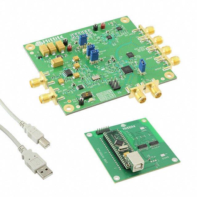
ICGOO电子元器件商城为您提供KSZ8081MNX-EVAL由Micrel设计生产,在icgoo商城现货销售,并且可以通过原厂、代理商等渠道进行代购。 KSZ8081MNX-EVAL价格参考¥662.84-¥662.84。MicrelKSZ8081MNX-EVAL封装/规格:评估和演示板和套件, KSZ8081MNX Ethernet PHY Interface Evaluation Board。您可以下载KSZ8081MNX-EVAL参考资料、Datasheet数据手册功能说明书,资料中有KSZ8081MNX-EVAL 详细功能的应用电路图电压和使用方法及教程。
Microchip Technology的KSZ8081MNX-EVAL是一款评估板,主要用于评估KSZ8081MNX以太网PHY芯片的功能和性能。以下是该评估板的主要应用场景:

 1. 网络设备开发
   - KSZ8081MNX-EVAL适用于开发基于以太网的网络设备,例如路由器、交换机、网关等。它可以帮助工程师测试和验证KSZ8081MNX芯片在网络通信中的表现,包括数据传输速率、信号完整性以及与其他网络设备的兼容性。

 2. 工业自动化
   - 在工业自动化领域,该评估板可用于开发支持以太网通信的工业控制器、PLC(可编程逻辑控制器)或远程I/O模块。通过评估KSZ8081MNX的性能,确保其能够满足工业环境下的高可靠性和实时性要求。

 3. 嵌入式系统设计
   - 对于嵌入式系统开发者,KSZ8081MNX-EVAL可以用来设计具有以太网功能的嵌入式设备,如智能家居设备、安防摄像头、工业传感器等。评估板允许开发者测试芯片的功耗、延迟和稳定性,从而优化系统设计。

 4. 物联网(IoT)应用
   - 在物联网领域,该评估板可用于开发支持以太网连接的智能设备。例如,家庭自动化设备、环境监测系统或智能家电可以通过KSZ8081MNX实现稳定可靠的网络连接。

 5. 汽车电子
   - KSZ8081MNX-EVAL还可用于汽车电子系统的开发,例如车载信息娱乐系统或高级驾驶辅助系统(ADAS)。评估板可以帮助工程师测试以太网在汽车环境中的抗干扰能力和数据传输性能。

 6. 教育与研究
   - 在学术和研究环境中,该评估板可用作教学工具或实验平台,帮助学生和研究人员了解以太网PHY的工作原理及其在实际系统中的应用。

 主要功能特点
   - 支持10/100 Mbps以太网通信。
   - 提供易于使用的接口,便于连接主机系统进行测试。
   - 集成必要的硬件组件,简化评估过程。
   - 支持多种工作模式,包括全双工和半双工模式。

通过KSZ8081MNX-EVAL评估板,用户可以快速验证KSZ8081MNX芯片的功能,并根据具体需求调整设计参数,从而加速产品开发周期。
| 参数 | 数值 |
| 产品目录 | 编程器,开发系统嵌入式解决方案 |
| 描述 | BOARD EVALUATION FOR KSZ8081MNX以太网开发工具 10/100 PHY, 0.11u - Evaluation Board |
| 产品分类 | |
| 品牌 | Micrel |
| 产品手册 | |
| 产品图片 |
|
| rohs | 否无铅 / 符合限制有害物质指令(RoHS)规范要求 |
| 产品系列 | 通信开发工具,以太网开发工具,Micrel KSZ8081MNX-EVAL- |
| 数据手册 | |
| 产品型号 | KSZ8081MNX-EVAL |
| 主要属性 | - |
| 主要用途 | 接口,以太网 PHY |
| 产品 | Evaluation Boards |
| 产品种类 | 以太网开发工具 |
| 使用的IC/零件 | KSZ8081MNX |
| 其它名称 | 576-4170 |
| 商标 | Micrel |
| 封装 | Bulk |
| 嵌入式 | 否 |
| 工作电源电压 | 1.8 V, 2.5 V, 3.3 V |
| 工具用于评估 | KSZ8081MNX |
| 所含物品 | 板 |
| 接口类型 | MII |
| 最大工作温度 | + 70 C |
| 最小工作温度 | 0 C |
| 标准包装 | 1 |
| 特色产品 | http://www.digikey.cn/product-highlights/zh/ksz8081-physicallayer-transceivers/52476 |
| 用于 | KSZ8081MNX |
| 类型 | Ethernet Transceivers |
| 系列 | KSZ8081 |
| 辅助属性 | - |


- 商务部:美国ITC正式对集成电路等产品启动337调查
- 曝三星4nm工艺存在良率问题 高通将骁龙8 Gen1或转产台积电
- 太阳诱电将投资9.5亿元在常州建新厂生产MLCC 预计2023年完工
- 英特尔发布欧洲新工厂建设计划 深化IDM 2.0 战略
- 台积电先进制程称霸业界 有大客户加持明年业绩稳了
- 达到5530亿美元!SIA预计今年全球半导体销售额将创下新高
- 英特尔拟将自动驾驶子公司Mobileye上市 估值或超500亿美元
- 三星加码芯片和SET,合并消费电子和移动部门,撤换高东真等 CEO
- 三星电子宣布重大人事变动 还合并消费电子和移动部门
- 海关总署:前11个月进口集成电路产品价值2.52万亿元 增长14.8%

PDF Datasheet 数据手册内容提取
KSZ8081MNX / KSZ8091MNX 10Base-T/100Base-TX Physical Layer Transceiver Evaluation Board User’s Guide Revision 1.0 / August 2012 © Micrel, Inc. 2012 All rights reserved Micrel is a registered trademark of Micrel and its subsidiaries in the United States and certain other countries. All other trademarks are the property of their respective owners. The information furnished by Micrel in this datasheet is believed to be accurate and reliable. However, no responsibility is assumed by Micrel for its use. Micrel reserves the right to change circuitry and specifications at any time without notification to the customer. Micrel Products are not designed or authorized for use as components in life support appliances, devices or systems where malfunction of a product can reasonably be expected to result in personal injury. Life support devices or systems are devices or systems that (a) are intended for surgical implant into the body or (b) support or sustain life, and whose failure to perform can be reasonably expected to result in a significant injury to the user. A Purchaser's use or sale of Micrel Products for use in life support appliances, devices or systems is at Purchaser's own risk and Purchaser agrees to fully indemnify Micrel for any damages resulting from such use or sale. Micrel, Inc. 2180 Fortune Drive San Jose, CA 95131 U.S.A. 408-944-0800 (voice) 408-474-1000 (fax) http://www.Micrel.com
KSZ8081MNX / KSZ8091MNX 10Base-T/100Base-TX Evaluation Board User’s Guide Revision History Revision Date Summary of Changes 1.0 8/15/12 Initial Release Micrel, Inc. August 15, 2012 Rev. 1.0 2/13
KSZ8081MNX / KSZ8091MNX 10Base-T/100Base-TX Evaluation Board User’s Guide Table of Contents 1.0 Introduction ............................................................................. 5 2.0 Board Features ........................................................................ 5 3.0 Evaluation Kit Contents .......................................................... 5 4.0 Hardware Description ............................................................. 6 4.1 MII (Media Independent Interface) ......................................................................... 7 4.2 Jumper Setting & Definition .................................................................................. 9 4.3 Test Point Definition ............................................................................................. 12 4.4 RJ-45 Connector ................................................................................................... 12 4.5 LED Indicators ...................................................................................................... 12 5.0 Bill of Materials ...................................................................... 13 Micrel, Inc. August 15, 2012 Rev. 1.0 3/13
KSZ8081MNX / KSZ8091MNX 10Base-T/100Base-TX Evaluation Board User’s Guide List of Figures Figure 1. KSZ8081MNX Evaluation Board ..................................................................................... 6 Figure 2. KSZ8081MNX-EVAL interfacing with KSZ8463MLI Evaluation Board ........................... 7 List of Tables Table 1. Connector J2 - MII Pin Definition ...................................................................................... 8 Table 2. KSZ8081MNX-EVAL / KSZ8091MNX-EVAL Strapping Jumper Definition ...................... 9 Table 3. KSZ8081MNX-EVAL / KSZ8091MNX-EVAL Loopback Jumper Definition ...................... 9 Table 4. KSZ8081MNX-EVAL / KSZ8091MNX-EVAL Miscellaneous Jumper Definition ............ 10 Table 5. Strapping Pin Definitions for KSZ8081MNX-EVAL / KSZ8091MNX-EVAL Jumpers ..... 11 Table 6. KSZ8081MNX-EVAL / KSZ8091MNX-EVAL Test Point Definition ................................ 12 Table 7. KSZ8081MNX / KSZ8091MNX LED Definition .............................................................. 12 Micrel, Inc. August 15, 2012 Rev. 1.0 4/13
KSZ8081MNX / KSZ8091MNX 10Base-T/100Base-TX Evaluation Board User’s Guide 1.0 Introduction The KSZ8081MNX / KSZ8091MNX is a 10Base-T/100Base-TX Physical Layer Transceiver with an MII MAC interface. It utilizes a unique mixed-signal design to extend signaling distance while reducing power consumption, and offers HP Auto MDI/MDI-X for reliable detection of and correction for crossover and straight-through cables, eliminating the need to differentiate between crossover and straight-through cables. The KSZ8091MNX has all the identical rich features of the KSZ8081MNX plus support for Energy Efficient Ethernet (EEE) and Wake-on-LAN (WOL). The KSZ8081MNX / KSZ8091MNX come in a 32-pin, lead-free QFN package and provides an ideal solution for 10Base-T/100Base-TX applications that have tight PCB board space. The KSZ8081MNX and KSZ8091MNX Eval Boards (KSZ8081MNX-EVAL and KSZ8091MNX- EVAL) provide a convenient platform to evaluate the features of the device. All configuration pins are accessible either by jumpers, test points or interface connectors. 2.0 Board Features Micrel KSZ8081MNX or KSZ8091MNX 10Base-T/100Base-TX Physical Layer Transceiver RJ-45 Jack for Fast Ethernet cable interface HP Auto MDI/MDI-X for automatic detection and correction for straight-through and crossover cables MII (Media Independent Interface) Connector to interface with a MAC controller 2 LED Indicators for status and activity Jumpers to configure strapping pins Manual Reset Button for quick reboot after re-configuration of strapping pins 3.0 Evaluation Kit Contents The KSZ8081MNX and KSZ8091MNX Evaluation Kits include the following hardware: KSZ8081MNX or KSZ8091MNX Evaluation Board A design package with the following collaterals that can be downloaded from Micrel’s website at http://www.micrel.com KSZ8081MNX / KSZ8091MNX Eval Board Schematic (PDF and OrCAD DSN file) KSZ80x1 (32-QFN) Eval Board Gerber Files (PDF version included) KSZ8081MNX / KSZ8091MNX Eval Board User’s Guide (this document) KSZ8081MNX and KSZ8091MNX IBIS Models and the KSZ8081MNX / KSZ8081RNB and KSZ8091MNX / KSZ8091RNB Datasheets which are also available from Micrel’s website. Micrel, Inc. August 15, 2012 Rev. 1.0 5/13
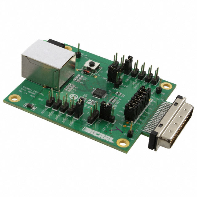
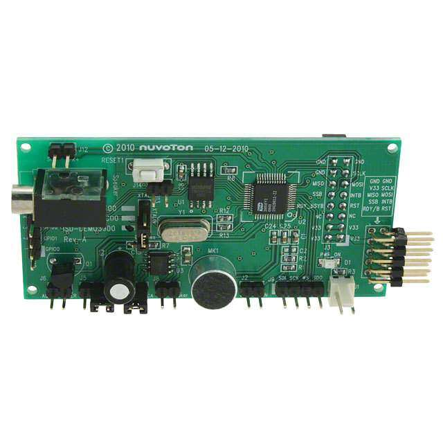
KSZ8081MNX / KSZ8091MNX 10Base-T/100Base-TX Evaluation Board User’s Guide 4.0 Hardware Description The KSZ8081MNX-EVAL / KSZ8091MNX-EVAL (shown in Figure 1) comes in a compact form factor and plugs directly into boards with Ethernet MACs that expose the MII interface. Configuration of the KSZ8081MNX / KSZ8091MNX is accomplished through on-board jumper selections and/or by PHY register access via the MDC/MDIO management pins of the MII Interface. Figure 1. KSZ8081MNX Evaluation Board Features include an RJ-45 Jack for Fast Ethernet cable connection, programmable LED indicators for reporting link status and activity, and a manual reset button for quick reboot after re- configuration of strapping pins. The KSZ8081MNX-EVAL / KSZ8091MNX-EVAL receives +5V DC input power through its MII connector. Micrel, Inc. August 15, 2012 Rev. 1.0 6/13
KSZ8081MNX / KSZ8091MNX 10Base-T/100Base-TX Evaluation Board User’s Guide 4.1 MII (Media Independent Interface) The KSZ8081MNX-EVAL / KSZ8091MNX-EVAL receives power and accesses MII data and management information from the MII connector J2. Figure 2 shows the KSZ8081MNX-EVAL / KSZ8091MNX-EVAL connected to the Micrel KSZ8463MLI Evaluation Board. Figure 2. KSZ8081MNX-EVAL interfacing with KSZ8463MLI Evaluation Board The MII interface is defined by Clause 22 of the IEEE 802.3 Specification. MII Management (MIIM) is conducted thru pins MDC (clock line) and MDIO (data line). MIIM allows upper-layer devices to monitor and control the states of the KSZ8081MNX / KSZ8091MNX. An external device with MDC/MDIO capability can be used to read the PHY status or configure the PHY registers. The MIIM frame format and timing information can be found in the KSZ8081MNX and KSZ8091MNX datasheets and in Clause 22 of the IEEE 802.3 Specification. The Eval Board has a 40-pin male edge connector that interfaces with and plugs directly into Fast Ethernet MAC boards with the mating AMP 787170-4 (40-pin, right angle, female) connector. Table 1 lists the pin outs for the MII interface on connector J2. Micrel, Inc. August 15, 2012 Rev. 1.0 7/13
KSZ8081MNX / KSZ8091MNX 10Base-T/100Base-TX Evaluation Board User’s Guide Pin # Signal Pin # Signal 1 +5V 21 +5V 2 MDIO 22 Ground 3 MDC 23 Ground 4 RXD3 24 Ground 5 RXD2 25 Ground 6 RXD1 26 Ground 7 RXD0 27 Ground 8 RXDV 28 Ground 9 RXCLK 29 Ground 10 RXER 30 Ground 11 TXER 31 Ground 12 TXCLK 32 Ground 13 TXEN 33 Ground 14 TXD0 34 Ground 15 TXD1 35 Ground 16 TXD2 36 Ground 17 TXD3 37 Ground 18 COL 38 Ground 19 CRS 39 Ground 20 +5V 40 +5V Table 1. Connector J2 - MII Pin Definition Micrel, Inc. August 15, 2012 Rev. 1.0 8/13
KSZ8081MNX / KSZ8091MNX 10Base-T/100Base-TX Evaluation Board User’s Guide 4.2 Jumper Setting & Definition At power-up, the KSZ8081MNX / KSZ8091MNX is configured using the chip’s internal pull-up and pull-down resistors with its default strapping pin values. Jumpers are provided to override the default settings, allowing for quick configuration and re-configuration of the board. To override the default settings, simply select and close the desired jumper setting(s) and toggle the on-board manual reset button (S1) for the new setting(s) to take effect. The KSZ8081MNX-EVAL / KSZ8091MNX-EVAL strapping jumper settings are defined in Table 2 below. Jumper Definition Open (default) Close J3 PHYAD0 1 0 J4 PHYAD1 0 1 J5 PHYAD2 0 1 J6 CONFIG0 J7 CONFIG1 CONFIG[2:0] Mode J8 CONFIG2 [open, open, open] MII (default) [close, close, open] MII Back-to-Back All other CONFIG[2:0] settings not listed are reserved (not used). J9 Isolate Mode Disable Enable J10 Nway Auto-Negotiation Enable Disable J11 Forced Speed (KSZ8081 only) 100Base-TX 10Base-T J12 Forced Duplex Half Full J25 Broadcast Off – for PHY Address 0 Broadcast PHY address Unique PHY address J26 PME_N Pin Enable (KSZ8091 only) Disable Enable Table 2. KSZ8081MNX-EVAL / KSZ8091MNX-EVAL Strapping Jumper Definition The KSZ8081MNX-EVAL / KSZ8091MNX-EVAL has another set of jumpers that may be used to loopback the MII interface. To loopback, all six jumpers must be installed. The individual jumpers are defined in Table 3. Jumper MII Signals Normal Operation MII Loopback Mode J13 RXDV / TXEN Open Close J14 RXC / TXC Open Close J16 RXD2 / TXD2 Open Close J17 RXD1 / TXD1 Open Close J18 RXD0 / TXD0 Open Close J19 RXD3 / TXD3 Open Close Table 3. KSZ8081MNX-EVAL / KSZ8091MNX-EVAL Loopback Jumper Definition Micrel, Inc. August 15, 2012 Rev. 1.0 9/13
KSZ8081MNX / KSZ8091MNX 10Base-T/100Base-TX Evaluation Board User’s Guide The last group of jumpers is defined in Table 4 below. These jumpers are not related to reset strapping, nor to loopback. Two jumpers are used to set the VDDIO voltage, and one jumper is used to route pin 31 as dependent on the device part number. Note that for the eval board to function, a jumper must be installed on JP3. If pins 1 & 2 of JP3 are closed, then a jumper must also be installed on JP10. For the KSZ8091MNX, a jumper must be installed on pins 2 & 3 of JP11. Jumper Definition Close pins 1, 2 Close pins 2, 3 JP3 VDDIO voltage selection: 3.3V / low VDDIO set by JP10 VDDIO = 3.3V JP10 VDDIO low voltage selection 1.8V_2.5V = 1.8V 1.8V_2.5V = 2.5V JP11 Pin 31 connection (LED1 or TXER) For KSZ8081 only For KSZ8091 only (pin 31 = LED1) (pin 31 = TXER) Table 4. KSZ8081MNX-EVAL / KSZ8091MNX-EVAL Miscellaneous Jumper Definition Table 5 lists the strapping pin definitions for the KSZ8081MNX-EVAL / KSZ8091MNX-EVAL jumpers. Jumper Pin Pin Name Pin Function J5 15 PHYAD2 The PHY Address is latched at power-up / reset and is J4 14 PHYAD1 configurable to any value from 0 to 7. J3 13 PHYAD0 The default PHY Address is 00001. PHY Address 00000 is enabled only if the B-CAST_OFF strapping pin is pulled high. PHY Address bits [4:3] are always set to ‘00’. J8 18 CONFIG2 The CONFIG[2:0] strap-in pins are latched at power-up / J7 29 CONFIG1 reset and are defined as follows: J6 28 CONFIG0 CONFIG[2:0] Mode 000 MII (default) 110 MII Back-to-Back All other CONFIG[2:0] settings not listed are reserved (not used). J9 20 ISO ISOLATE mode Pull-up = Enable Pull-down (default) = Disable At the de-assertion of reset, this pin value is latched into register 0h bit 10. Micrel, Inc. August 15, 2012 Rev. 1.0 10/13
KSZ8081MNX / KSZ8091MNX 10Base-T/100Base-TX Evaluation Board User’s Guide Jumper Pin Pin Name Pin Function J11 31 SPEED SPEED mode (KSZ8081 only) Pull-up (default) = 100Mbps Pull-down = 10Mbps At the de-assertion of reset, this pin value is latched into register 0h bit 13 as the Speed Select, and also is latched into register 4h (Auto-Negotiation Advertisement) as the Speed capability support. J12 16 DUPLEX DUPLEX mode Pull-up (default) = Half Duplex Pull-down = Full Duplex At the de-assertion of reset, this pin value is latched into register 0h bit 8 as the Duplex Mode. J10 30 NWAYEN Nway Auto-Negotiation Enable Pull-up (default) = Enable Auto-Negotiation Pull-down = Disable Auto-Negotiation At the de-assertion of reset, this pin value is latched into register 0h bit 12. J25 19 B-CAST_OFF Broadcast Off – for PHY Address 0 Pull-up = PHY Address 0 is set as a unique PHY address Pull-down (default) = PHY Address 0 is set as a broadcast PHY address At the de-assertion of reset, this pin value is latched by the chip. J26 22 PME_EN PME_N Output Pin for Wake-On-LAN Function (KSZ8091 only) Pull-up = Enable Pull-down = Disable At the de-assertion of reset, this pin value is latched into the chip. N/A 21 NAND_Tree# NAND Tree Mode Pull-up (default) = Disable Pull-down = Enable At the de-assertion of reset, this pin value is latched by the chip. Table 5. Strapping Pin Definitions for KSZ8081MNX-EVAL / KSZ8091MNX-EVAL Jumpers Micrel, Inc. August 15, 2012 Rev. 1.0 11/13
KSZ8081MNX / KSZ8091MNX 10Base-T/100Base-TX Evaluation Board User’s Guide 4.3 Test Point Definition The KSZ8081MNX-EVAL / KSZ8091MNX-EVAL has four test points. They are defined in the following table. Test Point Definition TP1 Pin 21 (with external pull-up) KSZ8081: Interrupt KSZ8091: Interrupt or PME_N2 TP2 Ground TP3 Ground TP7 Pin 30 KSZ8081: LED0 KSZ8091: LED0 or PME_N1 Table 6. KSZ8081MNX-EVAL / KSZ8091MNX-EVAL Test Point Definition 4.4 RJ-45 Connector The RJ-45 Connector (J1) is a TDK TLA-6T718A or similar integrated magnetic jack. It connects to standard CAT-5 Ethernet cable to interface with 10Base-T / 100Base-TX Ethernet devices. 4.5 LED Indicators A dual LED indicator (LED1) is located adjacent to the RJ-45 Connector. The top LED and bottom LED are connected to LED1 (pin 31) and LED0 (pin 30) respectively. The two LEDs are programmable to LED mode ‘00’ or ‘01’ via register 1Fh bits [5:4], and are defined in the following table. LED Mode LED1 (pin 31) LED0 (pin 30) 00 Pin LED Link/ Pin LED Speed State Definition Activity State Definition 10Base-T H OFF No Link H OFF 100Base-Tx L ON Link L ON Activity Toggle Blinking 01 Pin LED Pin Activity Link Definition State Definition State No Activity H OFF No Link H OFF Activity Toggle Blinking Link L ON 10 Reserved – not used Reserved – not used 11 Reserved – not used Reserved – not used Table 7. KSZ8081MNX / KSZ8091MNX LED Definition Micrel, Inc. August 15, 2012 Rev. 1.0 12/13
KSZ8081MNX / KSZ8091MNX 10Base-T/100Base-TX Evaluation Board User’s Guide 5.0 Bill of Materials KSZ8081MNX / KSZ8091MNX Eval Board, Schematic Revision 1.0 Item Quantity Reference Description Package 1 2 C1,C2 47uF / Tantalum B-size 2 1 C3 22uF / Tantalum B-size 3 10 C4,C5,C7,C10,C11,C12, 0.1uF 0603 C49,C51,C57,C58 4 4 C6,C8,C48,C50 10uF / Tantalum A-size 5 1 C9 2.2uF A-size 6 2 C16,C17 22pF 0603 7 1 C52 470pF 0603 8 1 D1 1N4148 DO-35 / axial lead 9 2 FB1,FB7 Ferrite Bead 1206 10 1 J1 RJ-45 Mag Jack thru hole / PC mount 11 1 J2 Male MII Connector PCB edge mount 12 18 J3,J4,J5,J6,J7,J8,J9,J10, Header 2X1 thru hole / 0.1" pitch J11,J12,J13,J14,J16 J17,J18,J19,J25,J26 13 3 JP3,JP10,JP11 Header 3X1 thru hole / 0.1" pitch 14 1 LED1 LEDx2 / Green thru hole / 0.1" pitch 15 1 R1 100K 0603 16 1 R2 10K 0603 17 9 R3,R25,R26,R27,R28, 4.7K 0603 R29,R30,R102,R103 18 10 R4,R5,R6,R7,R8,R9,R16, 33 0603 R17,R20,R21 19 1 R112 680 0603 20 1 R15 6.49K 0603 21 2 R22,R24 220 0603 22 5 R18,R23,R31,R32,R33 1K 0603 23 2 R111,R113 1.5K 0603 24 1 S1 SW PUSHBUTTON SMT 25 4 TP1,TP2,TP3,TP7 TestPoint thru hole / 0.1" pitch KSZ8081MNX or 26 1 U1 KSZ8091MNX 32-pin QFN 27 1 U2 MIC5216-3.3YM5 SOT-23-5 28 1 U7 MIC5207YM5 SOT-23-5 29 1 Y1 Xtal 25MHz +/-50ppm cylinder Micrel, Inc. August 15, 2012 Rev. 1.0 13/13
Mouser Electronics Authorized Distributor Click to View Pricing, Inventory, Delivery & Lifecycle Information: M icrel: KSZ8081MNX-EVAL KSZ8091MNX-EVAL