 Datasheet下载
- 型号: K102K15X7RH5TH5
- 制造商: Vishay
- 库位|库存: xxxx|xxxx
- 要求:
| 数量阶梯 | 香港交货 | 国内含税 |
| +xxxx | $xxxx | ¥xxxx |
查看当月历史价格
查看今年历史价格
K102K15X7RH5TH5产品简介:
ICGOO电子元器件商城为您提供K102K15X7RH5TH5由Vishay设计生产,在icgoo商城现货销售,并且可以通过原厂、代理商等渠道进行代购。 K102K15X7RH5TH5价格参考¥0.28-¥0.31。VishayK102K15X7RH5TH5封装/规格:陶瓷电容器, 1000pF ±10% 100V 陶瓷电容器 X7R 径向。您可以下载K102K15X7RH5TH5参考资料、Datasheet数据手册功能说明书,资料中有K102K15X7RH5TH5 详细功能的应用电路图电压和使用方法及教程。
Vishay BC Components的K102K15X7RH5TH5是一款陶瓷电容器,具有多种应用场景。该型号属于多层陶瓷电容器(MLCC),采用X7R电介质材料,具有较高的稳定性和可靠性。以下是其主要应用场景:

 1. 电源滤波
在电源电路中,K102K15X7RH5TH5可以用于滤波,帮助去除电源中的高频噪声和纹波。它能够有效地抑制电磁干扰(EMI),确保电源输出更加平稳,适用于开关电源、线性电源等设备。

 2. 耦合与去耦
该电容器常用于信号耦合和去耦电路中。在数字电路中,它可以为芯片提供稳定的电源电压,防止电源波动对芯片性能的影响。同时,在模拟电路中,它可以用于隔离不同阶段的信号,确保信号传输的纯净性。

 3. 振荡电路
K102K15X7RH5TH5可用于振荡电路中,作为定时元件或频率调节元件。它的高稳定性使得它在需要精确频率控制的应用中表现出色,如时钟电路、定时器等。

 4. 射频(RF)电路
由于其低损耗和高频率特性,该电容器适合用于射频电路中。它可以用于匹配网络、滤波器、谐振电路等,帮助提高射频信号的质量和传输效率。

 5. 汽车电子
在汽车电子系统中,K102K15X7RH5TH5可以应用于发动机控制单元(ECU)、传感器接口、车载娱乐系统等。其高温稳定性和抗振动特性使其能够在严苛的汽车环境中可靠工作。

 6. 工业自动化
在工业自动化领域,该电容器可以用于可编程逻辑控制器(PLC)、伺服驱动器、变频器等设备中,确保这些设备在复杂电磁环境下稳定运行。

 7. 消费电子产品
在消费电子产品中,如智能手机、平板电脑、智能手表等,K102K15X7RH5TH5可以用于电源管理、信号处理等模块,提升产品的性能和用户体验。

总的来说,K102K15X7RH5TH5凭借其优良的电气特性和稳定性,广泛应用于各种电子设备中,特别是在对可靠性要求较高的场合。
| 参数 | 数值 |
| 产品目录 | |
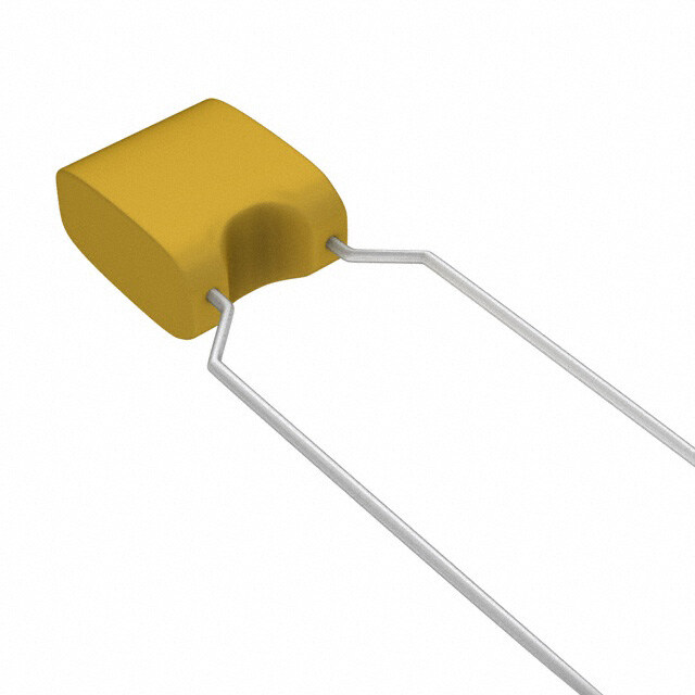
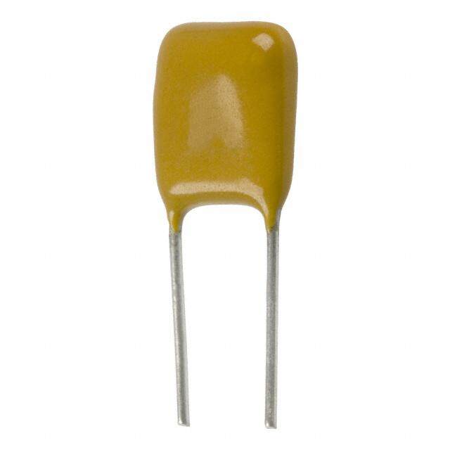
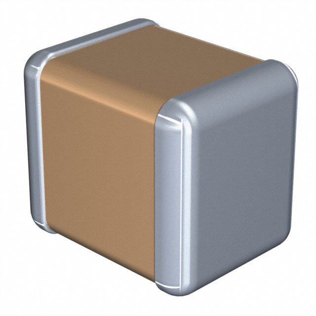
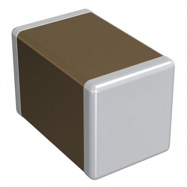
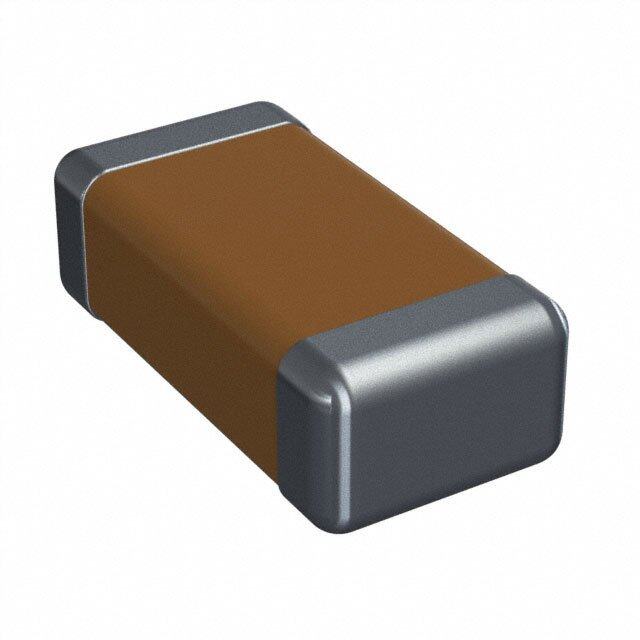
| 描述 | CAP CER 1000PF 100V 10% RADIAL多层陶瓷电容器MLCC - 含引线 1000pF 100volts 10% X7R 5mm LS |
| 产品分类 | |
| 品牌 | Vishay BC ComponentsVishay / BC Components |
| 产品手册 | |
| 产品图片 |
|
| rohs | RoHS 合规性豁免无铅 / 符合限制有害物质指令(RoHS)规范要求 |
| 产品系列 | MLCC,多层陶瓷电容器MLCC - 含引线,Vishay / BC Components K102K15X7RH5TH5Mono-Kap™ |
| 数据手册 | |
| 产品型号 | K102K15X7RH5TH5K102K15X7RH5TH5 |
| 产品 | General Type MLCCs |
| 产品目录绘图 |
|
| 产品目录页面 | |
| 产品种类 | 多层陶瓷电容器MLCC - 含引线 |
| 其它名称 | 2252-326-10102 |
| 包装 | 带卷 (TR) |
| 单位重量 | 150 mg |
| 厚度(最大值) | - |
| 商标 | Vishay / BC Components |
| 商标名 | Mono-Kap |
| 外壳宽度 | 2.5 mm |
| 外壳长度 | 4 mm |
| 外壳高度 | 4 mm |
| 大小/尺寸 | 0.157" 长 x 0.098" 宽(4.00mm x 2.50mm) |
| 安装类型 | 通孔 |
| 容差 | 10 %±10% |
| 封装 | Reel |
| 封装/外壳 | 径向 |
| 封装类型 | Dipped |
| 工作温度 | -55°C ~ 125°C |
| 工作温度范围 | - 55 C to + 125 C |
| 工厂包装数量 | 4000 |
| 应用 | 通用 |
| 引线形式 | 成型引线 |
| 引线直径 | 0.5 mm |
| 引线类型 | Outside Bend |
| 引线间距 | 0.197"(5.00mm) |
| 引线间隔 | 5 mm |
| 最大工作温度 | + 125 C |
| 最小工作温度 | - 55 C |
| 标准包装 | 4,000 |
| 温度系数 | X7R |
| 温度系数/代码 | X7R |
| 特性 | - |
| 电压-额定 | 100V |
| 电压额定值 | 100 V |
| 电压额定值DC | 100 V |
| 电容 | 1000 pF1000pF |
| 端接类型 | Radial |
| 等级 | - |
| 类型 | Radial Leads |
| 系列 | K |
| 高度-安装(最大值) | 0.257"(6.54mm) |


- 商务部:美国ITC正式对集成电路等产品启动337调查
- 曝三星4nm工艺存在良率问题 高通将骁龙8 Gen1或转产台积电
- 太阳诱电将投资9.5亿元在常州建新厂生产MLCC 预计2023年完工
- 英特尔发布欧洲新工厂建设计划 深化IDM 2.0 战略
- 台积电先进制程称霸业界 有大客户加持明年业绩稳了
- 达到5530亿美元!SIA预计今年全球半导体销售额将创下新高
- 英特尔拟将自动驾驶子公司Mobileye上市 估值或超500亿美元
- 三星加码芯片和SET,合并消费电子和移动部门,撤换高东真等 CEO
- 三星电子宣布重大人事变动 还合并消费电子和移动部门
- 海关总署:前11个月进口集成电路产品价值2.52万亿元 增长14.8%


PDF Datasheet 数据手册内容提取
K...V Series www.vishay.com Vishay BCcomponents Radial Leaded Multilayer Ceramic Capacitors For Automotive Applications Class 1 and Class 2, 50 V , 100 V , 200 V DC DC DC FEATURES • AEC-Q200 qualified with PPAP available • High reliability MLCC insert with wet build process • High operating temperature up to 160 °C • High capacitance with small size • Radial mounting style • Crimp and straight leadstyles • Parts compliant with ELV Directive Available • For fully RoHS-compliant alternative K...R Series, please refer to www.vishay.com/doc?45233 • Material categorization: for definitions of compliance please see www.vishay.com/doc?99912 Note * This datasheet provides information about parts that are RoHS-compliant and / or parts that are non-RoHS-compliant. For example, parts with lead (Pb) terminations are not RoHS-compliant. Please see the information / tables in this datasheet for details. APPLICATIONS • Automotive QUICK REFERENCE DATA DESCRIPTION VALUE Ceramic Class 1 2 Ceramic Dielectric C0G X7R X8R Voltage (V ) 50 100 200 50 100 200 50 DC Min. Capacitance (pF) 100 100 100 470 470 330 470 Max. Capacitance (pF) 10 000 10 000 1000 1 000 000 470 000 100 000 330 000 Mounting Radial MARKING CAPACITANCE RANGE Marking indicates capacitance value and tolerance in 100 pF to 1 μF accordance with “EIA 198”. TOLERANCE ON CAPACITANCE OPERATING TEMPERATURE RANGE ± 5 %, ± 10 %, ± 20 % -55 °C to +160 °C (50 % rated voltage above 150 °C) RATED VOLTAGE TEMPERATURE CHARACTERISTICS 50 V , 100 V , 200 V DC DC DC Class 1: C0G Class 2: X7R, X8R TEST VOLTAGE • 50 V and 100 V : 250 % of rated voltage DC DC SECTIONAL SPECIFICATIONS • 200 V : 200 % of rated voltage DC Climatic category (acc. to EN 60058-1) Class 1 and 2: 55/125/21 INSULATION RESISTANCE 100 G or 1000 F whichever is less at rated voltage within APPROVALS 2 min of charging. EIA 198 DISSIPATION FACTOR IEC 60384-9 Class 1: 0.1 % max. AEC-Q200 (at 1 MHz, 1 V where C 1000 pF; at 1 kHz, 1 V where C > 1000 pF) DESIGN Class 2: 2.5 % max. • The capacitors consist of a high reliability MLCC (at 1 kHz, 1 V) • The lead wires are 0.5 mm and are made of 100 % tinned copper clad steel wire (nickel wires for welding are available on request) • The capacitors may be supplied with straight or kinked leads having a lead spacing of 2.5 mm and 5.0 mm • Coating is made of yellow colored flame retardant epoxy resin in accordance with UL 94 V-0 Revision: 25-Feb-16 1 Document Number: 45213 For technical questions, contact: cmll@vishay.com THIS DOCUMENT IS SUBJECT TO CHANGE WITHOUT NOTICE. THE PRODUCTS DESCRIBED HEREIN AND THIS DOCUMENT ARE SUBJECT TO SPECIFIC DISCLAIMERS, SET FORTH AT www.vishay.com/doc?91000
K...V Series www.vishay.com Vishay BCcomponents LEAD CONFIGURATION AND DIMENSIONS in millimeters Wb Wb Wb Wb T H H H H SH SH SH SH L L L L 2.5 ± 0.8 5.0 ± 0.8 2.5 ± 0.8 5.0 ± 0.8 L2 H5 K2 K5 Component outline for Component outline for Component outline for Component outline for lead spacing 2.5 mm ± 0.8 mm lead spacing 5.0 mm ± 0.8 mm lead spacing 2.5 mm ± 0.8 mm lead spacing 5.0 mm ± 0.8 mm (straight leads) (flat bent leads) (outside kink) (outside kink) Lead MAXIMUM SEATING HEIGHT (SH) SIZE CODE Wb H T MAX. MAX. MAX. Diameter L2 H5 K2 K5 15 3.0 - 3.8 2.0 - 3.8 1.6 - 2.6 0.50 ± 0.05 1.6 2.6 3.5 3.5 20 4.3 - 5.1 2.5 - 5.1 1.9 - 3.2 0.50 ± 0.05 1.6 2.6 3.5 3.5 Notes • Bulk packed types have a standard lead length L = 30 mm ± 5 mm. • L2 and H5 are preferred styles. MARKING SIZE 15 SIZE 20 Vishay logo or BC logo Vishay logo or BC logo X X X X X X t t: Tolerance code XXX: Capacitance code XXX: Capacitance code Notes • Two significant digits followed by one digit for the multiplier as given following: 1 = * 10, 2 = * 100, 3 = * 1000, 4 = * 10 000, 5 = * 100 000 • The tolerance codes are J = 5 %, K = 10 %, M = 20 % ORDERING CODE INFORMATION K 104 K 15 X7R F 5 3 H 5 V 1 2 3 4 5 6 7 8 9 10 11 12 13 14 15 16 Product Capacitance Capacitance Size T.C. Rated Lead Packaging / Lead Lead AEC-Q200 Type (pF) Tolerance Code Code Voltage Diameter Lead Length Style Spacing qualified K = radial The first two digits J = ± 5 % Please Please F = 50 V 5 = 0.50 mm 3 = bulk H = flat 2 = 2.5 mm V = DC leaded are the significant K = ± 10 % refer to refer to H = 100 VDC ± 0.05 mm T = tape crimp 5 = 5.0 mmAEC-Q200 MLCC figures of M = ± 20 % relevant relevant K = 200 VDC and reel L = straight qualified capacitance and datasheetdatasheet U = ammo K = outside the last digit is a crimp multiplier as follows: 1 = * 10 2 = * 100 3 = * 1000 4 = * 10 000 5 = * 100 000 Revision: 25-Feb-16 2 Document Number: 45213 For technical questions, contact: cmll@vishay.com THIS DOCUMENT IS SUBJECT TO CHANGE WITHOUT NOTICE. THE PRODUCTS DESCRIBED HEREIN AND THIS DOCUMENT ARE SUBJECT TO SPECIFIC DISCLAIMERS, SET FORTH AT www.vishay.com/doc?91000
K...V Series www.vishay.com Vishay BCcomponents ORDERING CODES DIELECTRIC C0G CAP. 50 V 100 V 200 V (pF) DC DC DC 100 K101#15C0GF5###V K101#15C0GH5###V K101#15C0GK5###V 120 K121#15C0GF5###V K121#15C0GH5###V K121#15C0GK5###V 150 K151#15C0GF5###V K151#15C0GH5###V K151#15C0GK5###V 180 K181#15C0GF5###V K181#15C0GH5###V K181#15C0GK5###V 220 K221#15C0GF5###V K221#15C0GH5###V K221#15C0GK5###V 270 K271#15C0GF5###V K271#15C0GH5###V K271#15C0GK5###V 330 K331#15C0GF5###V K331#15C0GH5###V K331#15C0GK5###V 390 K391#15C0GF5###V K391#15C0GH5###V K391#15C0GK5###V 470 K471#15C0GF5###V K471#15C0GH5###V K471#15C0GK5###V 560 K561#15C0GF5###V K561#15C0GH5###V K561#15C0GK5###V 680 K681#15C0GF5###V K681#15C0GH5###V K681#15C0GK5###V 820 K821#15C0GF5###V K821#15C0GH5###V K821#15C0GK5###V 1000 K102#15C0GF5###V K102#15C0GH5###V K102#15C0GK5###V 1200 K122#15C0GF5###V K122#15C0GH5###V - 1500 K152#15C0GF5###V K152#15C0GH5###V - 1800 K182#15C0GF5###V K182#15C0GH5###V - 2200 K222#15C0GF5###V K222#20C0GH5###V - 2700 K272#15C0GF5###V K272#20C0GH5###V - 3300 K332#15C0GF5###V K332#20C0GH5###V - 3900 K392#15C0GF5###V K392#20C0GH5###V - 4700 K472#20C0GF5###V K472#20C0GH5###V - 5600 K562#20C0GF5###V K562#20C0GH5###V - 6800 K682#20C0GF5###V K682#20C0GH5###V - 8200 K822#20C0GF5###V K822#20C0GH5###V - 10 000 K103#20C0GF5###V K103#20C0GH5###V - Notes • Lead diameter is 0.5 mm • # 5th digit is capacitance tolerance code: ± 5 % = J; ± 10 % = K • # 13th digit is packaging code: bulk = 3; reel = T; ammo = U • # 14th digit is lead style code: L; H; K (L and H are preferred lead configuration) • # 15th digit is lead spacing code: 2.5 mm = 2; 5.0 mm = 5 RoHS-compliant Not RoHS-compliant, for fully RoHS-compliant alternative K...R Series, please refer to www.vishay.com/doc?45233 Revision: 25-Feb-16 3 Document Number: 45213 For technical questions, contact: cmll@vishay.com THIS DOCUMENT IS SUBJECT TO CHANGE WITHOUT NOTICE. THE PRODUCTS DESCRIBED HEREIN AND THIS DOCUMENT ARE SUBJECT TO SPECIFIC DISCLAIMERS, SET FORTH AT www.vishay.com/doc?91000
K...V Series www.vishay.com Vishay BCcomponents DIELECTRIC X7R CAP. 50 V 100 V 200 V (pF) DC DC DC 330 - - K331#15X7RK5###V 390 - - K391#15X7RK5###V 470 K471#15X7RF5###V K471#15X7RH5###V K471#15X7RK5###V 560 K561#15X7RF5###V K561#15X7RH5###V K561#15X7RK5###V 680 K681#15X7RF5###V K681#15X7RH5###V K681#15X7RK5###V 820 K821#15X7RF5###V K821#15X7RH5###V K821#15X7RK5###V 1000 K102#15X7RF5###V K102#15X7RH5###V K102#15X7RK5###V 1200 K122#15X7RF5###V K122#15X7RH5###V K122#15X7RK5###V 1500 K152#15X7RF5###V K152#15X7RH5###V K152#15X7RK5###V 1800 K182#15X7RF5###V K182#15X7RH5###V K182#15X7RK5###V 2200 K222#15X7RF5###V K222#15X7RH5###V K222#15X7RK5###V 2700 K272#15X7RF5###V K272#15X7RH5###V K272#15X7RK5###V 3300 K332#15X7RF5###V K332#15X7RH5###V K332#15X7RK5###V 3900 K392#15X7RF5###V K392#15X7RH5###V K392#15X7RK5###V 4700 K472#15X7RF5###V K472#15X7RH5###V K472#15X7RK5###V 5600 K562#15X7RF5###V K562#15X7RH5###V K562#15X7RK5###V 6800 K682#15X7RF5###V K682#15X7RH5###V K682#15X7RK5###V 8200 K822#15X7RF5###V K822#15X7RH5###V K822#15X7RK5###V 10 000 K103#15X7RF5###V K103#15X7RH5###V K103#15X7RK5###V 12 000 K123#15X7RF5###V K123#15X7RH5###V K123#15X7RK5###V 15 000 K153#15X7RF5###V K153#15X7RH5###V K153#15X7RK5###V 18 000 K183#15X7RF5###V K183#15X7RH5###V K183#15X7RK5###V 22 000 K223#15X7RF5###V K223#15X7RH5###V K223#15X7RK5###V 27 000 K273#15X7RF5###V K273#15X7RH5###V K273#15X7RK5###V 33 000 K333#15X7RF5###V K333#15X7RH5###V K333#20X7RK5###V 39 000 K393#15X7RF5###V K393#15X7RH5###V K393#20X7RK5###V 47 000 K473#15X7RF5###V K473#15X7RH5###V K473#20X7RK5###V 56 000 K563#15X7RF5###V K563#15X7RH5###V K563#20X7RK5###V 68 000 K683#15X7RF5###V K683#15X7RH5###V K683#20X7RK5###V 82 000 K823#15X7RF5###V K823#15X7RH5###V K823#20X7RK5###V 100 000 K104#15X7RF5###V K104#15X7RH5###V K104#20X7RK5###V 150 000 K154#15X7RF5###V K154#20X7RH5###V - 220 000 K224#20X7RF5###V K224#20X7RH5###V - 330 000 K334#20X7RF5###V K334#20X7RH5###V - 470 000 K474#20X7RF5###V K474#20X7RH5###V - 560 000 K564#20X7RF5###V - - 680 000 K684#20X7RF5###V - - 1 000 000 K105#20X7RF5###V - - Notes • Lead diameter is 0.5 mm • # 5th digit is capacitance tolerance code: ± 10 % = K; ± 20 % = M • # 13th digit is packaging code: bulk = 3; reel = T; ammo = U • # 14th digit is lead style code: L; H; K (L and H are preferred lead configuration) • # 15th digit is lead spacing code: 2.5 mm = 2; 5.0 mm = 5 RoHS-compliant Not RoHS-compliant, for fully RoHS-compliant alternative K...R Series, please refer to www.vishay.com/doc?45233 Revision: 25-Feb-16 4 Document Number: 45213 For technical questions, contact: cmll@vishay.com THIS DOCUMENT IS SUBJECT TO CHANGE WITHOUT NOTICE. THE PRODUCTS DESCRIBED HEREIN AND THIS DOCUMENT ARE SUBJECT TO SPECIFIC DISCLAIMERS, SET FORTH AT www.vishay.com/doc?91000
K...V Series www.vishay.com Vishay BCcomponents DIELECTRIC X8R CAP. 50 V (pF) DC 470 K471#15X8RF5###V 560 K561#15X8RF5###V 680 K681#15X8RF5###V 820 K821#15X8RF5###V 1000 K102#15X8RF5###V 1200 K122#15X8RF5###V 1500 K152#15X8RF5###V 1800 K182#15X8RF5###V 2200 K222#15X8RF5###V 2700 K272#15X8RF5###V 3300 K332#15X8RF5###V 3900 K392#15X8RF5###V 4700 K472#15X8RF5###V 5600 K562#15X8RF5###V 6800 K682#15X8RF5###V 8200 K822#15X8RF5###V 10 000 K103#15X8RF5###V 12 000 K123#15X8RF5###V 15 000 K153#15X8RF5###V 18 000 K183#15X8RF5###V 22 000 K223#15X8RF5###V 27 000 K273#15X8RF5###V 33 000 K333#15X8RF5###V 39 000 K393#15X8RF5###V 47 000 K473#15X8RF5###V 56 000 K563#15X8RF5###V 68 000 K683#15X8RF5###V 82 000 K823#15X8RF5###V 100 000 K104#15X8RF5###V 150 000 K154#15X8RF5###V 220 000 K224#20X8RF5###V 330 000 K334#20X8RF5###V Notes • Lead diameter is 0.5 mm • # 5th digit is capacitance tolerance code: ± 10 % = K; ± 20 % = M • # 13th digit is packaging code: bulk = 3; reel = T; ammo = U • # 14th digit is lead style code: L; H; K (L and H are preferred lead configuration) • # 15th digit is lead spacing code: 2.5 mm = 2; 5.0 mm = 5 RoHS-compliant Not RoHS-compliant, for fully RoHS-compliant alternative K...R Series, please refer to www.vishay.com/doc?45233 Revision: 25-Feb-16 5 Document Number: 45213 For technical questions, contact: cmll@vishay.com THIS DOCUMENT IS SUBJECT TO CHANGE WITHOUT NOTICE. THE PRODUCTS DESCRIBED HEREIN AND THIS DOCUMENT ARE SUBJECT TO SPECIFIC DISCLAIMERS, SET FORTH AT www.vishay.com/doc?91000
K...V Series www.vishay.com Vishay BCcomponents TAPING AND PACKAGING LABELLING For example: Each reel is provided with a label showing the following details: manufacturer, K style, capacitance, tolerance, batch number, quantity of components, rated voltage, dielectric. On special request other designations can be shown. PACKAGING QUANTITIES AND BOX DIMENSIONS SMALLEST PACKAGING BOX DIMENSIONS PACKAGING SIZE CODE QUANTITY (SPQ) L x W x H (mm) 15 4000 Tape on reel 370 x 370 x 60 20 3000 Ammopack 15, 20 2500 335 x 290 x 50 Bulk (1) 15, 20 5000 245 x 120 x 65 Note (1) SPQ contains one or a multiple of poly-bags, 1000 units per bag. CAPACITORS ON TAPE P Δh Seating plane F P1 H0 H1 H L W1 W W0 A P0 D0 d L1 t DIMENSIONS PARAMETER SYMBOL mm INCH Cut-off length L 11.0 0.443 Lead end protrusion L1 1.0 0.039 Height to seating plane (straight leads) H 18.0 0.709 Height to seating plane (crimp leads) H 16.0 ± 0.5 0.630 ± 0.020 0 Top of component height H1 32 1.26 Body inclination h 0.0 ± 1.0 0.000 ± 0.039 Carrier tape width W 18.0 + 1.0 / - 0.5 0.709 + 0.039 / - 0.020 Hold down tape width W 15.0 REF. 0.591 REF. 0 Sprocket hole position W 9.00 + 0.075 / - 0.50 0.354 + 0.030 / - 0.020 1 2.50 + 0.60 / - 0.40 0.100 + 0.024 / - 0.016 Lead space F 5.00 + 0.60 / - 0.40 0.200 + 0.024 / - 0.016 Sprocket hole pitch P 12.70 ± 0.30 0.500 ± 0.012 0 Sprocket hole center to lead center at F = 2.5 mm 5.08 ± 0.70 0.200 ± 0.028 P Sprocket hole center to lead center at F = 5 mm 1 3.85 ± 0.70 0.150 ± 0.028 Sprocket hole diameter D 4.00 ± 0.30 0.157 ± 0.012 0 Overall tape thickness t 0.90 0.035 Wire lead diameter d 0.50 ± 0.05 0.020 ± 0.002 Taping pitch P 12.7 REF. 0.50 REF. Revision: 25-Feb-16 6 Document Number: 45213 For technical questions, contact: cmll@vishay.com THIS DOCUMENT IS SUBJECT TO CHANGE WITHOUT NOTICE. THE PRODUCTS DESCRIBED HEREIN AND THIS DOCUMENT ARE SUBJECT TO SPECIFIC DISCLAIMERS, SET FORTH AT www.vishay.com/doc?91000
K...V Series www.vishay.com Vishay BCcomponents REEL DATA REEL A maximum of 0.5 % of the total number of capacitors per 55.1 Max. reel may be missing. + 0 48- 2 A maximum of 1 consecutive vacant positions is followed by 6 consecutive components. 355.6 max. Tape begins and ends with a minimum of 4 empty positions (50 mm tape). Maximum of 5 splicers per reel. Direction of Arbor hole unreeling Ø 28 ± 1 REEL DIMENSIONS A K H H 2 1 L REEL SIZE (mm) A Outer diameter 355.6 max. L Hole diameter 28 ± 1 K Core diameter 90 H Internal width 48 + 0 / - 2 1 H External width 55 max. 2 AMMOPACK DATA AMMOPACK A maximum of 0.5 % of the total number of capacitors per pack may be missing. A maximum of 1 consecutive vacant positions is followed by 6 consecutive components. Tape begins and ends with a minimum of 4 empty positions 290 (50 mm tape). Maximum of 5 splicers per pack. 335 The cumulative pitch tolerance over 20 consecutive units is 50 not to exceed ± 1.0 mm. Lead space (F) shall be measured at (3.6 ± 0.5) mm from the capacitor seating plane. RELATED DOCUMENTS General Information www.vishay.com/doc?45214 Revision: 25-Feb-16 7 Document Number: 45213 For technical questions, contact: cmll@vishay.com THIS DOCUMENT IS SUBJECT TO CHANGE WITHOUT NOTICE. THE PRODUCTS DESCRIBED HEREIN AND THIS DOCUMENT ARE SUBJECT TO SPECIFIC DISCLAIMERS, SET FORTH AT www.vishay.com/doc?91000
Legal Disclaimer Notice www.vishay.com Vishay Disclaimer ALL PRODUCT, PRODUCT SPECIFICATIONS AND DATA ARE SUBJECT TO CHANGE WITHOUT NOTICE TO IMPROVE RELIABILITY, FUNCTION OR DESIGN OR OTHERWISE. Vishay Intertechnology, Inc., its affiliates, agents, and employees, and all persons acting on its or their behalf (collectively, “Vishay”), disclaim any and all liability for any errors, inaccuracies or incompleteness contained in any datasheet or in any other disclosure relating to any product. Vishay makes no warranty, representation or guarantee regarding the suitability of the products for any particular purpose or the continuing production of any product. To the maximum extent permitted by applicable law, Vishay disclaims (i) any and all liability arising out of the application or use of any product, (ii) any and all liability, including without limitation special, consequential or incidental damages, and (iii) any and all implied warranties, including warranties of fitness for particular purpose, non-infringement and merchantability. Statements regarding the suitability of products for certain types of applications are based on Vishay’s knowledge of typical requirements that are often placed on Vishay products in generic applications. Such statements are not binding statements about the suitability of products for a particular application. It is the customer’s responsibility to validate that a particular product with the properties described in the product specification is suitable for use in a particular application. Parameters provided in datasheets and / or specifications may vary in different applications and performance may vary over time. All operating parameters, including typical parameters, must be validated for each customer application by the customer’s technical experts. Product specifications do not expand or otherwise modify Vishay’s terms and conditions of purchase, including but not limited to the warranty expressed therein. Except as expressly indicated in writing, Vishay products are not designed for use in medical, life-saving, or life-sustaining applications or for any other application in which the failure of the Vishay product could result in personal injury or death. Customers using or selling Vishay products not expressly indicated for use in such applications do so at their own risk. Please contact authorized Vishay personnel to obtain written terms and conditions regarding products designed for such applications. No license, express or implied, by estoppel or otherwise, to any intellectual property rights is granted by this document or by any conduct of Vishay. Product names and markings noted herein may be trademarks of their respective owners. © 2017 VISHAY INTERTECHNOLOGY, INC. ALL RIGHTS RESERVED Revision: 08-Feb-17 1 Document Number: 91000
Mouser Electronics Authorized Distributor Click to View Pricing, Inventory, Delivery & Lifecycle Information: V ishay: K105K20X7RF53H5 K271K15X7RH53L2 K471J15C0GF53H5 K180J15C0GF53L2 K224K20X7RF5TH5 K224M20X7RF5TH5 K330J15C0GH53L2 K102J15C0GF53H5 K100J15C0GF5TL2 K332K15X7RF5TL2 K180J15C0GF5TH5 K472J20C0GF53L2 K222K15X7RF5TK2 K331K15X7RF5TL2 K222K15X7RF53H5 K154K20X7RF53H5 K222J15C0GF53L2 K102J15C0GF5TH5 K122J15C0GF5TL2 K560J15C0GF5TH5 K102K15X7RH5TH5 K103K15X7RF5TH5 K472K15X7RF5TL2 K681J15C0GF53L2 K391J15C0GF53L2 K181J15C0GF53L2 K102K15X7RH53L2 K222K15X7RH53L2 K104K20X7RH5TH5 K104K20X7RH5TL2 K104K20X7RF53H5 K471J15C0GF53L2 K103M15Z5UF53L2 K101K15C0GF53L2 K221K15C0GH53L2 K104K20X7RH53H5 K104K15X7RF5TK2 K104K15X7RF5TH5 K104M20X7RH53L2 K221K15X7RF53L2 K102K15X7RF53L2 K101K15C0GH53L2 K150J15C0GH53L2 K103K15X7RH5TH5 K104M15X7RF5TH5 K224M20X7RF53H6-X2 K181J15C0GH5TH5 K102K15X7RK5TH5 K224K20X7RH5WH5 K270J15C0GF5TL2 K103K20X7RL5TH5 225232514473 K105M20X7RF53H5 K102M15X7RF5UL2 K102K15X7RH5TL2 K102J20C0GH53L2 K101J15C0GH53L2 K102J15C0GF53L2 K103M15X7RF53L2 K334M20X7RF53H5 K103K15X7RF53L2 K104M15X7RF53L2 K104M15X7RF53K2 K102K20C0GH53L2 K220K15C0GH53L2 K100K15C0GH53L2 K180J15C0GFVBWA K100J15C0GF53L2 K220J15C0GF53L2 K104K15X7RF53L2 K103K15X7RH53L2 K100K15C0GF53L2 K102K15X7RF5TL2 K105Z20Y5VF5TH5 K151J15C0GF5TH5 K104Z15Y5VF5TL2 K561J15C0GF5TL2 K683K15X7RF5TL2 K331J15C0GF5TH5 K101J15C0GF5TL2 K104Z15Y5VE5TH5 K474Z20Y5VF5TH5 K680J15C0GF5TL2 K270J15C0GF5TH5 K681K15X7RF5TL2 K104Z15Y5VF5TH5 K471J15C0GF5TL2 K821J15C0GF5TL2 K221J15C0GH5TL2 K101J15C0GH5TH5 K103K15X7RH5TL2 K103Z15Y5VF5TH5 K221J15C0GH5TH5 K102K15X7RF5TH5 K180J15C0GF5TL2 K105Z20Y5VF5TL2 K473K15X7RF5TL2 K103Z15Y5VE5TH5 K100J15C0GH5TL2 K220J15C0GH5TL2