ICGOO在线商城 > 电路保护 > TVS - 混合技术 > IXBOD1-10
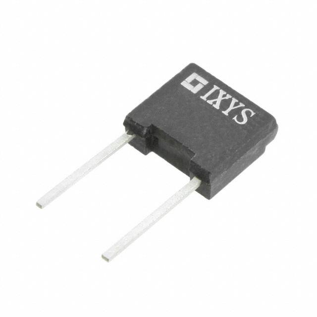
- 型号: IXBOD1-10
- 制造商: IXYS
- 库位|库存: xxxx|xxxx
- 要求:
| 数量阶梯 | 香港交货 | 国内含税 |
| +xxxx | $xxxx | ¥xxxx |
查看当月历史价格
查看今年历史价格
IXBOD1-10产品简介:
ICGOO电子元器件商城为您提供IXBOD1-10由IXYS设计生产,在icgoo商城现货销售,并且可以通过原厂、代理商等渠道进行代购。 IXBOD1-10价格参考。IXYSIXBOD1-10封装/规格:TVS - 混合技术, 。您可以下载IXBOD1-10参考资料、Datasheet数据手册功能说明书,资料中有IXBOD1-10 详细功能的应用电路图电压和使用方法及教程。
IXYS品牌的IXBOD1-10是一款属于TVS(瞬态电压抑制)混合技术类别的保护器件,主要用于电子电路中的过电压和瞬态浪涌保护。其典型应用场景包括工业控制设备、电源系统、通信设备以及可再生能源系统(如太阳能逆变器)等对电压稳定性要求较高的领域。

该器件结合了多种保护技术的优势,具备快速响应瞬态过电压的能力,能有效吸收雷击、电感负载切换或静电放电(ESD)引起的高压脉冲,保护后续敏感元器件(如MOSFET、IGBT、集成电路等)免受损坏。IXBOD1-10特别适用于直流母线电压较高或环境电磁干扰较强的场合,常用于功率半导体模块的并联保护,提升系统可靠性与安全性。

此外,在电机驱动、UPS(不间断电源)和轨道交通电子系统中,IXBOD1-10也广泛用于抑制开关噪声和电压尖峰。其高耐流能力和稳定性使其在恶劣工作环境下仍能保持长期可靠运行,是现代电力电子系统中重要的保护元件之一。
| 参数 | 数值 |
| 产品目录 | |
| 描述 | IC SGL DIODE BOD 0.9A 1000V FP硅对称二端开关元件 1 Amps 1000V |
| 产品分类 | |
| 品牌 | IXYS |
| 产品手册 | |
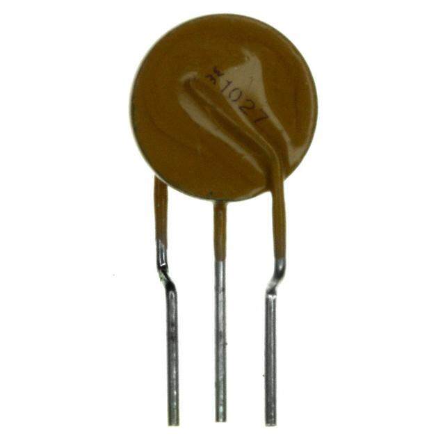
| 产品图片 |
|
| rohs | 符合RoHS无铅 / 符合限制有害物质指令(RoHS)规范要求 |
| 产品系列 | 晶体闸流管,硅对称二端开关元件,IXYS IXBOD1-10- |
| 数据手册 | |
| 产品型号 | IXBOD1-10 |
| 不重复通态电流 | 200 A |
| 产品种类 | 硅对称二端开关元件 |
| 供应商器件封装 | FP 壳 |
| 保持电流Ih最大值 | 30 mA |
| 关闭状态漏泄电流(在VDRMIDRM下) | 20 uA |
| 其它名称 | IXBOD110 |
| 功率(W) | - |
| 包装 | 散装 |
| 商标 | IXYS |
| 安装风格 | Through Hole |
| 封装 | Bulk |
| 封装/外壳 | 径向 |
| 封装/箱体 | FP-2 |
| 工作结温 | - 40 C to + 125 C |
| 工厂包装数量 | 100 |
| 应用 | 高电压 |
| 开启状态电压 | 1.7 V |
| 技术 | 混合技术 |
| 最大工作温度 | + 125 C |
| 最大转折电流IBO | 15 mA |
| 最小工作温度 | - 40 C |
| 标准包装 | 100 |
| 电压-工作 | - |
| 电压-箝位 | 1000V(1kV) |
| 电流额定值 | 900 mA |
| 电路数 | 1 |
| 系列 | IXBOD1-10 |
| 转折电流VBO | 1 kV |




- 商务部:美国ITC正式对集成电路等产品启动337调查
- 曝三星4nm工艺存在良率问题 高通将骁龙8 Gen1或转产台积电
- 太阳诱电将投资9.5亿元在常州建新厂生产MLCC 预计2023年完工
- 英特尔发布欧洲新工厂建设计划 深化IDM 2.0 战略
- 台积电先进制程称霸业界 有大客户加持明年业绩稳了
- 达到5530亿美元!SIA预计今年全球半导体销售额将创下新高
- 英特尔拟将自动驾驶子公司Mobileye上市 估值或超500亿美元
- 三星加码芯片和SET,合并消费电子和移动部门,撤换高东真等 CEO
- 三星电子宣布重大人事变动 还合并消费电子和移动部门
- 海关总署:前11个月进口集成电路产品价值2.52万亿元 增长14.8%

PDF Datasheet 数据手册内容提取
Breakover Diodes Applications (cid:1)Transient voltage protection (cid:1)High-voltage switches (cid:1)Crowbar (cid:1)Lasers (cid:1)Pulse generators i I H I BO V V V H BO Application Note H - 6 Remark: For special selection of more than 2 pieces IXBOD 1-... for every break down voltage of V > 2000 V please contact us. BO © 2000 IXYS All rights reserved H - 1
IXBOD 1 -06...10 Single Breakover Diode V = 600-1000V BO I = 0.9 A AVM V Standard BO V Types A K 600 –50 IXBOD 1 -06 700 –50 IXBOD 1 -07 800 –50 IXBOD 1 -08 900 –50 IXBOD 1 -09 1000 –50 IXBOD 1 -10 Symbol Conditions Ratings I T =125°C; V = 0,8x V 20 (cid:181)A D VJ BO V V (T ) = V [1 + K (T - 25°C)] BO BO VJ BO, 25°C T VJ I f = 50 HZ; T = 50°C 1.4 A RMS amb connection pins soldered to printed circuit (conductor 0,035x2mm) I 0.9 A AVM I t = 0.1 ms; T = 50°C non repetitive 200 A SM p amb I²t t = 0.1 ms; T = 50°C 2 A2s p amb T -40...+125 °C amb T -40...+125 °C stg T 125 °C VJm Dimensions in mm (1 mm = 0.0394") K Temperatur coefficient of V 2·10-3 K-1 T BO K coefficient for energy per pulse E (material constant) 700 K/Ws P P R - natural convection 60 K/W thJA - with air speed 2 m/s 45 K/W Weight 1 g Symbol Conditions Characteristic Values I T = 25°C 15 mA BO VJ I T = 25°C 30 mA H VJ V T = 25°C 4 - 8 V H VJ (dv/dt) T = 50°C; V = 0.67·(V + 100V) > 1000 V/µs C VJ D BO K A (di/dt) T = 125°C; V = V ; I = 80A; f = 50 Hz 200 A/µs C VJ D BO T t T = 125°C V = 0.67·V ; V = 0V 150 µs q(typ) VJ D BO R dV/dt = 200V/µs; I = 80A; di/dt = -10A/µs (lin.) T V T =125°C; I = 5A 1.7 V T VJ T V For power-loss calculations only 1.1 V (TO) r T = 125°C 0.12 Ω T VJ 0 IXYS reserve at these the right to change limits, test conditions and dimensions; Data according to IEC 60747 3 0 H - 2 © 2000 IXYS All rights reserved
IXBOD 1 -06...10 Fig. 1 Energy per pulse for trapezoidal current wafeforms (see waveform definition). Fig. 2 Energy per pulse for exponentially decaying current pulse (see waveforms definition). V = 0 m/s a V = 2 m/s a [V] [K/W] Z V thJA T T = 125(cid:176)C VJ T = 25(cid:176)C VJ iT [A] t [s] Fig. 3 On-state voltage Fig. 4 Transient thermal resistance. © 2000 IXYS All rights reserved H - 3
IXBOD 1 -12R...42R(D) Breakover Diode Modules Version: R Version: RD V Standard BOD - V Standard BOD - V Standard BOD - BO BO BO V Types Elements V Types Elements V Types Elements 1200 ±50 IXBOD 1 -12R(D) 2 2000 ±50 IXBOD 1 -20R(D) 3 3400 ±100 IXBOD 1 -34R 4 1300 ±50 IXBOD 1 -13R(D) 2 2100 ±50 IXBOD 1 -21R(D) 3 3600 ±100 IXBOD 1 -36R 4 1400 ±50 IXBOD 1 -14R(D) 2 2200 ±50 IXBOD 1 -22R(D) 3 3800 ±100 IXBOD 1 -38R 4 1500 ±50 IXBOD 1 -15R(D) 2 2300 ±50 IXBOD 1 -23R(D) 3 4000 ±100 IXBOD 1 -40R 4 1600 ±50 IXBOD 1 -16R(D) 2 2400 ±50 IXBOD 1 -24R(D) 3 4200 ±100 IXBOD 1 -42R 4 1700 ±50 IXBOD 1 -17R(D) 2 2500 ±50 IXBOD 1 -25R(D) 3 1800 ±50 IXBOD 1 -18R(D) 2 2600 ±100 IXBOD 1 -26R(D) 3 1900 ±50 IXBOD 1 -19R(D) 2 2800 ±100 IXBOD 1 -28R(D) 3 3000 ±100 IXBOD 1 -30R(D) 3 3200 ±100 IXBOD 1 -32R(D) 3 2-3 BODs Symbol Test Conditions 2 BODs 3 BODs 4 BODs D-Version I T = 125°C;V = 0,8x V 100 100 100 100 (cid:181)A D VJ BO V V (T ) = V [1 + K (T - 25°C)] BO BO VJ BO, 25°C T VJ I f = 50 HZ; T = 50°C 2.0 1.4 1.1 0.3 A RMS amb connection pins soldered to printed circuit (conductor 0,035x2mm) I 1.25 0.9 0.7 0.2 A AVM I t = 0.1 ms; T = 50°C non repetitive 200 200 200 50 A SM p amb I²t t = 0.1 ms; T = 50°C 2 2 2 0.125 A2s p amb V T =125°C; I = 5A 3.4 5.1 6.8 27 V T VJ T V For power-loss calculations only 2.2 3.3 4.4 17.5 V (TO) r T =125°C 0.24 0.36 0.48 3 Ω T VJ T -40...+125 -40...+125 -40...+125 -40...+125 °C amb T -40...+125 -40...+125 -40...+125 -40...+125 °C stg T 125 125 125 125 °C VJm K Temperatur coefficient of V 2·10-3 2·10-3 2·10-3 2·10-3 K-1 T BO K coefficient for energy per pulse E (material constant) 700 700 700 700 K/Ws P P R - natural convection 20 20 20 20 K/W thJA - with air speed 2 m/s 16 16 16 16 K/W Weight typical 14 14 14 14 g Symbol Test Conditions Characteristic Values both Versions R & RD 2 BODs 3 BODs 4 BODs I T = 25°C 15 15 15 mA BO VJ I T = 25°C 30 30 30 mA H VJ V T = 25°C 4 - 8 4 - 8 4 - 8 V H VJ (dv/dt) T = 50°C; V = 0.67·(V + 100V) C VJ D BO - V bis 1500V > 1000 - - V/µs BO - V 1600 - 2000V > 1500 - - V/µs BO - V 2100 - 2500V - > 2000 - V/µs BO - V 2600 - 3000V - > 2500 - V/µs BO - V 3200 - 3400V - - > 3000 V/µs BO - V 3600 - 4200V - - > 3500 V/µs BO (di/dt) T = 125°C; V = V ; I = 80A; f = 50 Hz 200 200 200 A/µs C VJ D BO T t T = 125°C V = 0.67·V ; V = 0V 150 150 150 µs q(typ) VJ D BO R dv/dt = 200V/µs; I = 80A; di/dt = -10A/µs (lin.) T 2 IXYS reserve at these the right to change limits, test conditions and dimensions; Data according to IEC 60747 3 0 H - 4 © 2000 IXYS All rights reserved
IXBOD 1 -12R...42R(D) A K K A Dimensions in mm (1 mm = 0.0394") Fig. 5 Energy per pulse for single BOD element Fig. 6 Energy per pulse for single BOD element for trapezoidal wave current. E must be multiplied for exponentially decaying current pulse. E must P P by number of elements for total energy. be multiplied by number of elements for total energy. n = number of BOD-Elements in series [V] [K/W] VT ZthJA Va = 0 m/s V = 2 m/s a iT [A] t [s] Fig. 7 On-state voltage at T = 125(cid:176)C. Fig. 8 Transient thermal resistance. VJ © 2000 IXYS All rights reserved H - 5
Application Protection of thyristors against overvoltages in forward i direction. Thyristor V (T ) = V [1+KT(T - 25°C)] BO VJ BO, 25°C VJ BOD V D Calculation example a. The maximum junction temperature shall be b. If following these steady-state conditions an calculated for a module IXBOD 1 -30R at an overload for 1 minute occurs with I = 60 A and a TM ambient temperature T = 60 (cid:176)C, an exponentially pulse-width tp = 4 µs at the same operating a decaying current I = 40A, a pulsewidth tp = 2 µs, frequency f = 50 Hz, then the resulting maximum TM an operating frequency f = 50 Hz and natural junction temperature is calculating as follows: convection. From the diagram Fig. 6 the energy per pulse is obtained: T = T + (E -E ) (cid:149) n (cid:149) f (cid:149)Z (t) + Kp (cid:149) (E -E ) VJmax2 VJmax1 p2 p1 thJA p2 p1 E = 6 x 10⁻³ Ws p1 For a module IXBOD1-30R the number of single The diagrams Fig. 11 and Fig. 8 show IXBOD elements is: n = 3 E = 14x10-3 Ws p2 Z (t = 1min) = 12K/W thJA At natural air cooling the thermal resistance junction to ambient amounts to (Fig.8): From what follows: R = 20K/W T = 82.2 + 14.4 + 5,6 = 102.2 (cid:176)C thJA VJmax2 and the unknown temperature can be calculated as: which is allowed because the maximum admissible junction temperature T = 125 (cid:176)C. VJM T = T + n (cid:149) f (cid:149) E (cid:149) R + K (cid:149) E VJmax1 a p thJA p p T = 60 + 18 + 4.2 = 82.2(cid:176)C VJmax1 H - 6 © 2000 IXYS All rights reserved
Example of a circuit A simple emergency triggering circuit. R R T : Thyristor 1 3 R : Current limiting resistance (0 - 200 Ω) 1 D : Series-diode (fast recovery diode) 1 D 1 D : Protection diode 3 T D : Zener diode, typical V : 3-6 V IXBOD 4 Z z R , C : Protection against parasitic triggering; 2 2 recommended values: D D R2 : 100 - 1000 Ω R C4 3 C3 C : 22 - 47 nF 2 2 2 R , C : Snubber network of the thyristor 3 3 Notice 1. A IXBOD element has a maximum reverse 40 blocking voltage of 10V. A I 20 R 2. For higher reverse voltages a fast, soft recovery diode must be connected in series (Fig. 9). 10 This diode must fulfill the conditions of Fig. 10. 8 i 6 4 I R 2 t t B 1 Fast recovery IXBOD single 0,1 (cid:181)s 1 2 3 5 7 10 diode or t IXBOD module B Fig. 10 Maximum peak value of the Fig. 9 IXBOD protection by a fast recovery reverse current admissible for a given diode. pulse-width t , which is required for the B suitable fast recovery series-diode. © 2000 IXYS All rights reserved H - 7
H - 8 © 2000 IXYS All rights reserved
 Datasheet下载

