ICGOO在线商城 > ISPPAC-POWR6AT6-01NN32I
 Datasheet下载
- 型号: ISPPAC-POWR6AT6-01NN32I
- 制造商: Lattice
- 库位|库存: xxxx|xxxx
- 要求:
| 数量阶梯 | 香港交货 | 国内含税 |
| +xxxx | $xxxx | ¥xxxx |
查看当月历史价格
查看今年历史价格
ISPPAC-POWR6AT6-01NN32I产品简介:
ICGOO电子元器件商城为您提供ISPPAC-POWR6AT6-01NN32I由Lattice设计生产,在icgoo商城现货销售,并且可以通过原厂、代理商等渠道进行代购。 提供ISPPAC-POWR6AT6-01NN32I价格参考以及LatticeISPPAC-POWR6AT6-01NN32I封装/规格参数等产品信息。 你可以下载ISPPAC-POWR6AT6-01NN32I参考资料、Datasheet数据手册功能说明书, 资料中有ISPPAC-POWR6AT6-01NN32I详细功能的应用电路图电压和使用方法及教程。
| 参数 | 数值 |
| 产品目录 | 集成电路 (IC) |
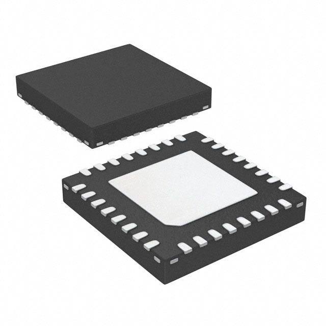
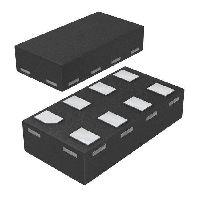
| 描述 | IC ISP POWER SUPPLY PROGR 32QFN |
| 产品分类 | |
| 品牌 | Lattice Semiconductor Corporation |
| 数据手册 | |
| 产品图片 |
|
| 产品型号 | ISPPAC-POWR6AT6-01NN32I |
| rohs | 无铅 / 符合限制有害物质指令(RoHS)规范要求 |
| 产品系列 | ispPAC® |
| 供应商器件封装 | 32-QFN 裸露焊盘(5x5) |
| 包装 | 托盘 |
| 安装类型 | 表面贴装 |
| 封装/外壳 | 32-VFQFN 裸露焊盘 |
| 工作温度 | -40°C ~ 85°C |
| 应用 | 电源控制器/监控器 |
| 标准包装 | 490 |
| 电压-电源 | 2.8 V ~ 3.96 V |
| 电压-输入 | -0.3 V ~ 5.9 V |
| 电流-电源 | 10mA |


- 商务部:美国ITC正式对集成电路等产品启动337调查
- 曝三星4nm工艺存在良率问题 高通将骁龙8 Gen1或转产台积电
- 太阳诱电将投资9.5亿元在常州建新厂生产MLCC 预计2023年完工
- 英特尔发布欧洲新工厂建设计划 深化IDM 2.0 战略
- 台积电先进制程称霸业界 有大客户加持明年业绩稳了
- 达到5530亿美元!SIA预计今年全球半导体销售额将创下新高
- 英特尔拟将自动驾驶子公司Mobileye上市 估值或超500亿美元
- 三星加码芯片和SET,合并消费电子和移动部门,撤换高东真等 CEO
- 三星电子宣布重大人事变动 还合并消费电子和移动部门
- 海关总署:前11个月进口集成电路产品价值2.52万亿元 增长14.8%

PDF Datasheet 数据手册内容提取
ispPAC®-POWR6AT6 In-System Programmable Power Supply Monitoring and Margining Controller November 2013 Data Sheet DS1016 Features Application Block Diagram ■ Power Supply Margin and Trim Functions Vout 3.3V • Trim and margin up to six power supplies Trim (cid:129) Dynamic voltage control through I2C Vout (cid:129) Four hardware selectable voltage profiles 2.5V y (cid:129) Independent Digital Closed-Loop Trim function Trim uitr for each output 1.8V Vout Circ ■ Analog Input Monitoring Trim d ar (cid:129) Six analog monitor inputs Vout o B (cid:129) Differential input architecture for accurate POL#1 Trim her remote ground sensing Vout Ot (cid:129) 10-bit ADC for direct voltage measurements POL#2 Trim ■ 2-Wire (I2C/SMBus™ Compatible) Interface Vout (cid:129) Readout of the ADC POL#3 Trim (cid:129) Dynamic trimming/margining control ■ Other Features (cid:129) Programmable analog circuitry (cid:129) Wide supply range, 2.8V to 3.96V 6 Analog 6 Analog (cid:129) In-system programmable through JTAG Trim Outputs Monitor Inputs (cid:129) Industrial temperature range: -40°C to +85°C (cid:129) 32-pin QFNS (Quad Flat-pack, No lead, Saw- ADC CPU singulated) package1, only 5mm x 5mm, lead- Power Supply Margin/Trim free option Control I2C I2C Interface Bus Description ispPAC-POWR6AT6 Lattice’s Power Manager II ispPAC-POWR6AT6 is a general-purpose power-supply monitoring and margin- ing controller, incorporating in-system programmable analog functions implemented in non-volatile E2CMOS® mode. The operating voltage profile can be selected technology. The ispPAC-POWR6AT6 device provides using external hardware pins. six independent analog input channels to monitor up to six power supply test points. Each of these input chan- The on-chip 10-bit A/D converter can both be used to nels offers a differential input to support remote ground monitor the V voltage through the I2C bus as well as MON sensing. for implementing digital closed loop mode for maintain- ing the output voltage of all power supplies controlled by The ispPAC-POWR6AT6 incorporates six DACs for gen- the monitoring and trimming section of the ispPAC- erating a trimming voltage to control the output voltage POWR6AT6 device. of a power supply. The trimming voltage can be set to four hardware selectable preset values (voltage profiles) The I2C bus/SMBus interface allows an external micro- or can be dynamically loaded in to the DAC through the controller to measure the voltages connected to the I2C bus. Additionally, each power supply output voltage V analog monitor inputs and load the DACs for the MON can be maintained within 1% tolerance across various generation of the trimming voltages of the external DC- load conditions using the Digital Closed Loop Control DC converters. 1. Use 32-pin QFNS package for all new designs. Refer to PCN #13A-08 for 32-pin QFN package discontinuance. © 2013 Lattice Semiconductor Corp. All Lattice trademarks, registered trademarks, patents, and disclaimers are as listed at www.latticesemi.com/legal. All other brand or product names are trademarks or registered trademarks of their respective holders. The specifications and information herein are subject to change without notice. www.latticesemi.com 1 DS1016_01.5
ispPAC-POWR6AT6 Data Sheet Figure 3-1. ispPAC-POWR6AT6 Block Diagram A B M S K/ b C N O TE TL S0 S1 CD CA L L P P C C C C V V V V VMON1 Decoder TrimCell 1 DAC TRIM1 VMON1GS VMON2 Set Point TrimCell 2 DAC TRIM2 VMON2GS Registers VMON3 TrimCell 3 DAC TRIM3 VMON3GS ADC Control Logic VMON4 VMON4GS TrimCell 4 DAC TRIM4 OSC VMON5 VMON5GS TrimCell 5 DAC TRIM5 VMON6 VMON6GS TrimCell 6 DAC TRIM6 SCL I2C Interface JTAG Interface SDA ispPAC-POWR6AT6 G V T T T T N C D D C M D C O I K S J 2
ispPAC-POWR6AT6 Data Sheet Pin Descriptions Number Name Pin Type Voltage Range Description 7 VPS0 Digital Input VCCD Trim Select Input 0 8 VPS1 Digital Input VCCD Trim Select Input 1 CLTENb Enables closed loop trim process (asserted 6 Digital Input VCCD low) Signals that all TrimCells selected for closed- CLTLOCK/ loop trim have reached a trim locked condi- 9 Open Drain Output1 0V to 5.5V SMBA tion. Can be configured to be compliant with SMBus Alert protocol.2 15 VMON1 Analog Input -0.3V to 5.75V Voltage Monitor 1 Input 14 VMON1GS Analog Input -0.3V to 0.3V3 Voltage Monitor 1 Ground Sense 17 VMON2 Analog Input -0.3V to 5.75V Voltage Monitor 2 Input 16 VMON2GS Analog Input -0.3V to 0.3V3 Voltage Monitor 2 Ground Sense 19 VMON3 Analog Input -0.3V to 5.75V Voltage Monitor 3 Input 18 VMON3GS Analog Input -0.3V to 0.3V3 Voltage Monitor 3 Ground Sense 21 VMON4 Analog Input -0.3V to 5.75V Voltage Monitor 4 Input 20 VMON4GS Analog Input -0.3V to 0.3V3 Voltage Monitor 4 Ground Sense 23 VMON5 Analog Input -0.3V to 5.75V Voltage Monitor 5 Input 22 VMON5GS Analog Input -0.3V to 0.3V3 Voltage Monitor 5 Ground Sense 25 VMON6 Analog Input -0.3V to 5.75V Voltage Monitor 6 Input 24 VMON6GS Analog Input -0.3V to 0.3V3 Voltage Monitor 6 Ground Sense 32 GND Ground Ground Ground 12 VCCD4 Power 2.8V to 3.96V Core VCC, Main Power Supply 13 VCCA4 Power 2.8V to 3.96V Analog Power Supply 2 VCCJ Power 2.25V to 3.6V VCC for JTAG Logic Interface Pins -320mV to +320mV 31 TRIM1 Analog Output from Programmable Trim DAC Output 1 DAC Offset -320mV to +320mV 30 TRIM2 Analog Output from Programmable Trim DAC Output 2 DAC Offset -320mV to +320mV 29 TRIM3 Analog Output from Programmable Trim DAC Output 3 DAC Offset -320mV to +320mV 28 TRIM4 Analog Output from Programmable Trim DAC Output 4 DAC Offset -320mV to +320mV 27 TRIM5 Analog Output from Programmable Trim DAC Output 5 DAC Offset -320mV to +320mV 26 TRIM6 Analog Output from Programmable Trim DAC Output 6 DAC Offset 3
ispPAC-POWR6AT6 Data Sheet Pin Descriptions (Cont.) Number Name Pin Type Voltage Range Description 1 TDO Digital Output JTAG Test Data Out 3 TCK Digital Input JTAG Test Clock Input 5 TMS Digital Input JTAG Test Mode Select; Internal Pullup 4 TDI Digital Input JTAG Test Data In; Internal Pullup 10 SCL Digital Input I2C Serial Clock Input 11 SDA Digital I/O I2C Serial Data, Bi-directional Pin Die Pad NC No Connection No Internal Connection 1. Open-drain outputs require an external pull-up resistor to a supply. 2. Normally asserted low, but can be programmed to assert high (open) if desired. 3. The VMONxGS inputs are the ground sense line for each given VMON pin. The VMON input pins along with the VMONxGS ground sense pins implement a differential pair for each voltage monitor to allow remote sense at the load. VMONxGS lines must be connected and are not to exceed -0.3V to +0.3V in reference to the GND pin. 4. VCCA and VCCD pins must be connected together on the circuit board. 4
ispPAC-POWR6AT6 Data Sheet Absolute Maximum Ratings Absolute maximum ratings are shown in the table below. Stresses beyond those listed may cause permanent dam- age to the device. Functional operation of the device at these or any other conditions beyond those indicated in the recommended operating conditions of this specification is not implied. Symbol Parameter Conditions Min. Max. Units V Core supply -0.5 4.5 V CCD V Analog supply -0.5 4.5 V CCA V JTAG logic supply -0.5 6 V CCJ V Digital input voltage (all digital I/O pins) -0.5 6 V IN V V input voltage -0.5 6 V MON+ MON V V input voltage ground sense -0.5 6 V MONGS MON T Storage temperature -65 150 oC S T Ambient temperature -65 125 oC A Recommended Operating Conditions Symbol Parameter Conditions Min. Max. Units V V Core supply voltage at pin 2.8 3.96 V CCD, CCA V JTAG logic supply voltage at pin 2.25 3.6 V CCJ V Input voltage at digital input pins -0.3 5.5 V IN V Input voltage at V pins -0.3 5.9 V MON MON V Input voltage at V pins -0.3 0.3 V MONGS MONGS V Open-drain output voltage CLTLOCK/SMBA -0.3 5.5 V OUT T Ambient temperature during programming (Note 1) -40 85 oC APROG T Ambient temperature Power applied1 -40 85 oC A 1. The die pad on the bottom of the QFN/QFNS package does not need to be electrically or thermally connected to ground. Analog Specifications Symbol Parameter Conditions Min. Typ. Max. Units I 1 Supply current 10 mA CC I Supply current 1 mA CCJ 1. Includes currents on V and V supplies. CCD CCA Analog Voltage Monitor Inputs (V ) MON Symbol Parameter Conditions Min. Typ. Max. Units Input mode = Attenuated1 50 65 80 k¾ R Input resistance IN Input mode = Unattenuated 10 M¾ C Input capacitance 12 pF IN 1. True for Vmon input voltage from 600mV to 2.048V. Values less than 600mV will see higher input impedance values. 5
ispPAC-POWR6AT6 Data Sheet Margin/Trim DAC Output Characteristics Symbol Parameter Conditions Min Typ Max Units Resolution 8(7+sign) bits FSR Full scale range +/-320 mV LSB LSB step size 2.5 mV I Output source/sink current -200 200 µA OUT Offset 1 0.6 Bipolar zero output voltage Offset 2 0.8 V V BPZ (code=80h) Offset 3 1.0 Offset 4 1.25 DAC code changed from 80H to FFH or 2.5 ms TS TrimCell output voltage settling 80H to 00H time1 Single DAC code 256 µs change C_LOAD Maximum load capacitance 50 pF T Update time through I2C port2 260 µs UPDATEM Full scale DAC corre- Total open loop supply voltage TOSE sponds to ±5% supply -1 +1 % error3 voltage variation 1. To 1% of set value with 50pf load connected to trim pins. 2. Total time required to update a single TRIMx output value by setting the associated DAC through the I2C port. 3. This is the total resultant error in the trimmed power supply output voltage referred to any DAC code due to the DAC’s INL, DNL, gain, out- put impedance, offset error and bipolar offset error across the industrial temperature range and the ispPAC-POWR6AT6 operating V CCA and V ranges. CCD ADC Characteristics Symbol Parameter Conditions Min. Typ. Max. Units ADC resolution 10 Bits Programmable attenuator = 1 0 2.048 V VIN Input range full scale Programmable attenuator = 3 0 5.751 V Time from I2C request to complete one T Conversion complete time 2002 µs CONVERT conversion cycle Programmable attenuator = 1 2 mV ADC Step Size LSB Programmable attenuator = 3 6 mV Eattenuator Error due to attenuator Programmable attenuator = 3 +/- 0.1 % 1. Maximum voltage is limited by V pin (theoretical maximum is 6.144V). MONX 2. Minimum time to wait for valid ADC result. Applies when not reading the DONE status bit (via I2C) to determine ADC. ADC Error Budget Across Entire Operating Temperature Range Symbol Parameter Conditions Min. Typ. Max. Units Measurement Range 600 mV to 2.048V, -8 +/-4 8 mV VMONxGS > -100mV, Attenuator =1 Total Measurement Error at Measurement Range 600 mV to 2.048V, TADC Error +/-6 mV Any Voltage1 VMONxGS > -200mV, Attenuator =1 Measurement Range 0 to 600 mV, +/-10 mV VMONxGS > -200mV, Attenuator =1 1. Total error, guaranteed by characterization, includes INL, DNL, Gain, Offset, and PSR specs of the ADC. 6
ispPAC-POWR6AT6 Data Sheet Digital Specifications Over Recommended Operating Conditions Symbol Parameter Conditions Min. Typ. Max. Units I ,I Input leakage, no pull-up/pull-down +/-10 µA IL IH I Input pull-up current (TMS, TDI) 70 µA PU VPS[0:1], TDI, TMS, CLTENb, 0.8 V = V = 3.3V CCD CCJ V Voltage input, logic low1 V IL SCL, SDA 30% V CCD TDI, TMS, V = 2.5V 0.7 CCJ VPS[0:1], TDI, TMS, CLTENb, 2.0 V = V = 3.3V CCD CCJ V Voltage input, logic high1 V IH SCL, SDA 70% V V CCD CCD TDI, TMS, V = 2.5V 1.7 CCJ V CLTLOCK/SMBA I = 20mA 0.8 V OL SINK 1. CLTENb, VPS[0:1], SCL, SDA referenced to V ; TDO, TDI, TMS referenced to V . CCD CCJ I2C Port Characteristics 100KHz 400KHz Symbol Definition Min. Max. Min. Max. Units F I2C clock/data rate 1001 4001 KHz I2C T After start 4.7 0.6 us SU;STA T After start 4 0.6 us HD;STA T Data setup 250 100 ns SU;DAT T Stop setup 4 0.6 us SU;STO T Data hold; SCL= Vih_min = 2.1V 0.3 3.45 0.3 0.9 us HD;DAT T Clock low period 4.7 1.3 us LOW T Clock high period 4 0.6 us HIGH T Fall time; 2.25V to 0.65V 300 300 ns F T Rise time; 0.65V to 2.25V 1000 300 ns R T Detect clock low timeout 25 35 25 35 ms TIMEOUT T Device must be operational after power-on reset 500 500 ms POR T Bus free time between stop and start condition 4.7 1.3 us BUF 1. If F is less than 50kHz, then the ADC DONE status bit is not guaranteed to be set after a valid conversion request is completed. In this I2C case, waiting for the T minimum time after a convert request is made is the only way to guarantee a valid conversion is ready for CONVERT readout. When F is greater than 50kHz, ADC conversion complete is ensured by waiting for the DONE status bit. I2C 7
ispPAC-POWR6AT6 Data Sheet Timing for JTAG Operations Symbol Parameter Conditions Min. Typ. Max. Units t Program enable delay time 10 — — µs ISPEN t Program disable delay time 30 — — µs ISPDIS t High voltage discharge time, program 30 — — µs HVDIS t High voltage discharge time, erase 200 — — µs HVDIS t Falling edge of TCK to TDO active — — 10 ns CEN t Falling edge of TCK to TDO disable — — 10 ns CDIS t Setup time 5 — — ns SU1 t Hold time 10 — — ns H t TCK clock pulse width, high 20 — — ns CKH t TCK clock pulse width, low 20 — — ns CKL f Maximum TCK clock frequency — — 25 MHz MAX t Falling edge of TCK to valid output — — 10 ns CO t Verify pulse width 30 — — µs PWV t Programming pulse width 20 — — ms PWP Figure 3-2. Erase (User Erase or Erase All) Timing Diagram VIH TTSMCtaKSte VVVIIIHLL UpdattSeU-1I R tCKtHH tSUtG1 KRL un-Testt/HId le (Erase) tSU1 StCeKtHlHe ct-DR Scan Clock to Shift-IR state and shift in the Discharge Instruction, then clock to the Run-Test/Idle state tSU1 tCKtHH RtSUutG1n K-LT est/IdtSlCepKt eHH(c D ifieisdc bhtyS atUhr2eg Dea)tt aS US1h eet tCKtHH Figure 3-3. Programming Timing Diagram VIH TTCMKS VVVIIIHL L tSU1 tCKtHH tSUt1C KL tH tPWP tSU1 tCKtHH R state and shift in the next will stop the discharge process tSU1 tCKtHH tSUt1C KL tCKtHH State Update-IR Run-Test/Idle (Program) Select-DR Scan Clock to Shift-Instruction, which Update-IR I 8
ispPAC-POWR6AT6 Data Sheet Figure 3-4. Verify Timing Diagram VIH on cti TMS stru VIL ext In t t t t t t n t t t t SU1 H SU1 H SU1 H e SU1 H SU1 H tCKH tCKL tPWV tCKH n th tCKH tCKL tCKH VIH hift i TCK d s n VIL a e at st R hift-I State Update-IR Run-Test/Idle (Program) Select-DR Scan o S Update-IR ck t o Cl Figure 3-5. Discharge Timing Diagram t (Actual) HVDIS VIH e STTtCMaKtSe VVVIIIHLL UpdattSeU-1I R tCKtHH RtuSUntC1- KTLe st/Idle (tEH rase or P rogtrPaWmP)t SU1 StCeKtHlHe ct-DR Scan Clock to Shift-IR state and shift in the Verify nstruction, then clock to the Run-Test/Idle stat tSU1 tCKtHH RtSUut1Cn K-LT est/IdtlSCepKt eHH(cV ifeierdi fbyyt)P t WheV DatatAtS SPcUWht1ue Vae tl tCKtHH I 9
ispPAC-POWR6AT6 Data Sheet Theory of Operation Voltage Measurement with the On-chip Analog to Digital Converter (ADC) The ispPAC-POWR6AT6 has an on-chip analog to digital converter that can be used for measuring the voltages at the VMON inputs. The ADC is also used in closed loop trimming of DC-DC converters. Close loop trimming is cov- ered later in this document. Figure 3-6. ADC Monitoring VMON1 to VMON6 Programmable Attenuator + VMON 1 ÷3 / ÷1 – + VMON 2 ÷3 / ÷1 – To Closed Loop Trim Circuit + VMON 3 ÷3 / ÷1 – ADC ADC MUX 10 + VMON 4 ÷3 / ÷1 – To I2C Readout + Internal Register VMON 5 ÷3 / ÷1 VREF- – 2.048V + VMON 6 ÷3 / ÷1 – 3 From Closed From I2C Loop Trim ADC MUX Circuit Address Figure 3-6 shows the ADC circuit arrangement within the ispPAC-POWR6AT6 device. The ADC can measure all analog input voltages through the multiplexer, ADC MUX. The programmable attenuator between the ADC mux and VMON pins can be configured as divided-by-3 or divided-by-1 (no attenuation). The divided-by-3 setting is used to measure voltages from 0V to 6V range and divided-by-1 setting is used to measure the voltages from 0V to 2V range. A microcontroller can place a request for any VMON voltage measurement at any time through the I2C bus. Upon the receipt of an I2C command, the ADC will be connected to the I2C selected VMON through the ADC MUX. The ADC output is then latched into the I2C readout registers. 10
ispPAC-POWR6AT6 Data Sheet Calculation The algorithm to convert the ADC code to the corresponding voltage takes into consideration the attenuation bit value. In other words, if the attenuation bit is set, then ADC output logic multiplies the 10-bit ADC code by 3 to cal- culate the actual voltage at that VMON input. The following formula can always be used to calculate the actual volt- age from the ADC code. Voltage at the VMONx Pins VMONx = ADC code (12 bits1, converted to decimal) * 2mV 1Note: ADC_VALUE_HIGH (8 bits), ADC_VALUE_LOW (4 bits) read from I2C/SMBUS interface Controlling Power Supply Output Voltage with the Margin/ Trim Block One of the key features of the ispPAC-POWR6AT6 is its ability to make adjustments to the power supplies that it may also be monitoring. This is accomplished through the Trim and Margin Block of the device. The Trim and Mar- gin Block can adjust voltages of up to six different power supplies through TrimCells as shown in Figure 3-7. The DC-DC blocks in the figure represent virtually any type of DC power supply that has a trim or voltage adjustment input. This can be an off-the-shelf unit or custom circuit designed around a switching regulator IC. The interface between the ispPAC-POWR6AT6 and the DC power supply is represented by a single resistor (R1 to R6) to simplify the diagram. Each of these resistors represents a resistor network. Other control signals driving the Margin/Trim Block are: (cid:129) VPS [1:0] – Control signals from device pins common to all six TrimCells, which are used to select the active voltage profile for all TrimCells together. (cid:129) ADC input – Used to determine the trimmed DC-DC converter voltage. (cid:129) CLTENb – Used to enable closed loop trimming of all TrimCells together. Next to each DC-DC converter, four voltages are shown. These voltages correspond to the operating voltage profile of the Margin/Trim Block. When the VPS[1:0] = 00, representing Voltage Profile 0: (Voltage Profile 0 is recommended to be used for the nor- mal circuit operation) The output voltage of the DC-DC converter controlled by the Trim 1 pin of the ispPAC-POWR6AT6 will be 1V and that TrimCell is operating in closed loop trim mode. At the same time, the DC-DC converters controlled by Trim 2, Trim 3 and Trim 6 pins output 1.2V, 1.5V and 3.3V respectively. When the VPS[1:0] = 01, representing Voltage Profile 1 being active: The DC-DC output voltage controlled by Trim 1, 2, 3, and 6 pins will be 1.05V, 1.26V, 1.57V, and 3.46V. These sup- ply voltages correspond to 5% above their respective normal operating voltage (also called as margin high). Similarly, when VPS[1:0] = 11, all DC-DC converters are margined low by 5%. 11
ispPAC-POWR6AT6 Data Sheet Figure 3-7. ispPAC-POWR6AT6 Trim and Margin Block ispPAC-POWR6AT6 Margin/Trim Block VIN DC-DC Output Voltage Controlled by Profiles 0 1 2 3 TrimCell R1* DC-DC 1V (CLT) 1.05V 0.97V 0.95V Trim 1 #1 Trim-in (Closed Loop) VIN CLTENb 1.2V (I2C) 1.26V 1.16V 1.14V TrimCell R2* DC-DC Trim 2 oopontrol (I2C U#p2d ate) VIN Trim-in LC d e ec 1.5V (I2C) 1.57V 1.45V 1.42V sa VPS[0:1] Digital Clo2d IC Interf (IT2Cri mU#p3Cdealtel) Trim 3 R3* TriDmC-in- DC n a VIN 3.3V (EE) 3.46V 3.20V 3.13V CLTLOCK/SMBA TrimCell R6* DC-DC Trim 6 #6 Trim-in (Register 0) *Indicates resistor network (see Figure 8). Input From ADC Mux Read – 10-bit ADC Code There are six TrimCells in the ispPAC-POWR6AT6 device, enabling simultaneous control of up to six individual power supplies. Each TrimCell can generate up to four trimming voltages to control the output voltage of the DC-DC converter. Figure 3-8. TrimCell Driving a Typical DC-DC Converter VOUT VIN VOUT R3 DC-DC Converter TrimCell R1 DAC Trim #N R2 12
ispPAC-POWR6AT6 Data Sheet Figure 3-8 shows the resistor network between the TrimCell #N in the ispPAC-POWR6AT6 and the DC-DC con- verter. The values of these resistors depend on the type of DC-DC converter used and its operating voltage range. The method to calculate the values of the resistors R1, R2, and R3 are described in a separate application note. Voltage Profile Control The Margin / Trim Block of ispPAC-POWR6AT6 consists of six TrimCells. Because all six TrimCells in the Margin / Trim Block are controlled by a common voltage profile control signals, they all operate at the same voltage profile. The voltage profile control input comes from a pair of device pins: VPS0, VPS1. TrimCell Architecture The TrimCell block diagram is shown in Figure 3-9. The 8-bit DAC at the output provides the trimming voltage required to set the output voltage of a programmable supply. Each TrimCell can be operated in any one of the four voltage profiles. In each voltage profile the output trimming voltage can be set to a preset value. There are six 8-bit registers in each TrimCell that, depending on the operational mode, set the DAC value. Of these, four DAC values (DAC Register 0 to DAC Register 3) are stored in the E2CMOS memory while the remaining register contents are stored in volatile registers. Two multiplexers (Mode Mux and Profile Mux) control the routing of the code to the DAC. The Profile Mux can be controlled by common TrimCell voltage profile control signals. Figure 3-9. ispPAC-POWR6AT6 Output TrimCell TRIMCELL ARCHITECTURE VOLTAGE DAC REGISTER 3 8 PROFILE 3 (E2CMOS) VOLTAGE DAC REGISTER 2 8 PROFILE 2 (E2CMOS) 11 P PVROOLTFAILGEE 1 DAC(E R2CEMGIOSST)ER 1 8 0110 MUXROFIL 8 DAC TRIMx 00 E 8 DAC REGISTER 0 8 (E2CMOS) 2 8 PVROOLTFAILGEE 0 DAC R(IE2CG)ISTER MUXMODE CLOSED LOOP 8 TRIM REGISTER VOLTAGE PROFILE 0 MODE SELECT COMMON TrimCell FROM CLOSED LOOP (E2CMOS) VOLTAGE PROFILE TRIM CIRCUIT CONTROL Figure 3-7 shows four power supply voltages next to each DC-DC converter. When the Profile MUX is set to Volt- age Profile 3, the DC supply controlled by Trim 1 will be at 0.95V, the DC supply controlled by Trim 2 will be at 1.14V, 1.42V for Trim 3 and 3.13V for Trim 8. When Voltage Profile 0 is selected, Trim 1 will set the supply to 1V, Trim 2 and Trim 3 will be set by the values that have been loaded using I2C at 1.2 and 1.5V, and Trim 6 will be set to 3.3V. The following table summarizes the voltage profile selection and the corresponding DAC output trimming voltage. The voltage profile selection is common to all six TrimCells. 13
ispPAC-POWR6AT6 Data Sheet Table 3-1. TrimCell Voltage Profile and Operating Modes Trimming Voltage VPS[1:0] Selected Voltage Profile Selected Mode is Controlled by 11 Voltage Profile 3 — DAC Register 3 (E2CMOS) 10 Voltage Profile 2 — DAC Register 2 (E2CMOS) 01 Voltage Profile 1 — DAC Register 1 (E2CMOS) DAC Register 0 Select DAC Register 0 (E2CMOS) 00 Voltage Profile 0 DAC Register I2C Select DAC Register (I2C) Digital Closed Loop Trim Closed Loop Trim Register TrimCell Operation in Voltage Profiles 1, 2 and 3: The output trimming voltage is determined by the code stored in the DAC Registers 1, 2, and 3 corresponding to the selected Voltage Profile. TrimCell Operation in Voltage Profile 0: The Voltage Profile 0 has three operating modes. They are DAC Regis- ter 0 Select mode, DAC Register I2C Select mode and Closed Loop Trim mode. The mode selection is stored in the E2CMOS configuration memory. Each of the six TrimCells can be independently set to different operating modes during Voltage Profile 0 mode of operation. DAC Register 0 Select Mode: The contents of DAC register 0 are stored in the on-chip E2CMOS memory. When Voltage Profile 0 is selected, the DAC will be loaded with the value stored in DAC Register 0. DAC Register I2C Select Mode: This mode is used if the power management arrangement requires an external microcontroller to control the DC-DC converter output voltage. The microcontroller updates the contents of the DAC Register I2C on the fly to set the trimming voltage to a desired value. The DAC Register I2C is a volatile regis- ter and is reset to 80H (DAC at Bipolar zero) upon power-on. The external microcontroller writes the correct DAC code in this DAC Register I2C before enabling the programmable power supply. Digital Closed Loop Trim Mode Closed loop trim mode operation can be used when tight control over the DC-DC converter output voltage at a desired value is required. The closed loop trim mechanism operates by comparing the measured output voltage of the DC-DC converter with the internally stored voltage setpoint. The difference between the setpoint and the actual DC-DC converter voltage generates an error voltage. This error voltage adjusts the DC-DC converter output volt- age toward the setpoint. This operation iterates until the setpoint and the DC-DC converter voltage are equal. Figure 3-10 shows the closed loop trim operation of a TrimCell. At regular intervals (as determined by the Update Rate Control register) the ispPAC-POWR6AT6 device initiates the closed loop power supply voltage correction cycle through the following blocks: (cid:129) Non-volatile Setpoint register stores the desired output voltage (cid:129) On-chip ADC is used to measure the voltage of the DC-DC converter (cid:129) Three-state comparator is used to compare the measured voltage from the ADC with the Setpoint regis- ter contents. The output of the three state comparator can be one of the following: (cid:129) +1 if the setpoint voltage is greater than the DC-DC converter voltage (cid:129) -1 if the setpoint voltage is less than the DC-DC converter voltage (cid:129) 0 if the setpoint voltage is equal to the DC-DC converter voltage (cid:129) Channel polarity control determines the polarity of the error signal (cid:129) Closed loop trim register is used to compute and store the DAC code corresponding to the error voltage. The contents of the Closed Loop Trim will be incremented or decremented depending on the channel polar- ity and the three-state comparator output. If the three-state comparator output is 0, the closed loop trim reg- ister contents are left unchanged. (cid:129) The DAC in the TrimCell is used to generate the analog error voltage that adjusts the attached DC-DC con- verter output voltage. 14
ispPAC-POWR6AT6 Data Sheet Figure 3-10. Digital Closed Loop Trim Operation SETPOINT (E2CMOS) E2CMOS Registers TrimCell CHANNEL POLARITY DAC Register 3 (E2CMOS) DAC Register 2 TRIMx DAC DAC Register 1 DAC Register 0 ThDrIeGeI-TSAtaLt e DAC Register I2C Profile Control R* +/-1 COMPARE Closed Loop (+1/0/-1) Trim Register Profile 0 Mode TRIMIN UPDATE Control (E2CMOS) DC-DC RATE CONVERTER CONTROL VMONx VOUT ADC GND POWR6AT6 E2CMOS *Indicates resistor network (see Figure 8). The closed loop trim cycle interval is programmable and is set by the update rate control register. The following table lists the programmable update interval that can be selected by the update rate register. Table 3-2. Output DAC Update Rate in Digital Closed Loop Mode Update Rate Update Control Value Interval 00 432 µs 01 1.06 ms 10 8.74 ms 11 16.9 ms Closed Loop Trim Control Using the CLTENb Pin There is a one-to-one relationship between the selected TrimCell and the corresponding VMON input for the closed loop operation. For example, if TrimCell 3 is used to control the power supply in the closed loop trim mode, VMON3 must be used to monitor its output power supply voltage. The CLTENb enable pin (active low) simultaneously starts the closed loop trimming process for all ispPAC- POWR6AT6 trim outputs so configured. Behavior of individual trim output pins is defined using Lattice PAC- Designer design software and stored in the ispPAC-POWR6AT6's non-volatile E2CMOS memory. In addition to a closed-loop trim control option, two other configuration alternatives are available. The first stores a fixed, or static, value for a given trim output in E2CMOS memory. The second enables dynamic trim adjustments to be made using an external microcontroller via the ispPAC-POWR6AT6's I2C interface bus. Neither of these options is affected by the CLTENb pin, however. When the ispPAC-POWR6AT6's CLTENb pin goes low, closed-loop trimming is enabled. When CLTENb subse- quently goes high, there is a brief delay after which closed-loop trimming is suspended. The delay is the time required for ispPAC-POWR6AT6 control logic to complete a trim update cycle. Table 3-2 shows typical times for update cycles based on which of four trim rates is initially chosen in PAC-Designer. When the trim process is halted, it should also be noted the trim output DACs have constant voltage output levels (corresponding to their last input code setting). This condition can be safely maintained indefinitely, but resuming closed-loop trimming (by tak- ing CLTENb low) better insures power supplies remain precisely adjusted under all possible conditions. When re- enabled, closed-loop trimming restarts where it left off. In this sense, the CLTENb pin can be thought of as a “pause” control for closed-loop trim. 15
ispPAC-POWR6AT6 Data Sheet It should also be noted that whenever the VPS0 and VPS1 pins are not both low, they effectively stop closed-loop trim the same way the CLTENb pin does when it goes high. That is, whenever an alternate trim mode (other than VPS0=0 and VPS1=0) is selected, the trim process is suspended as described above. Assuming the CLTENb pin is asserted, when both VPS0 and VPS1 are low again, closed-loop trimming will resume where it left off. It is recommended that the CLTENb pin not be activated until after any necessary power supply sequencing is completed to prevent an “open loop” condition from occurring. Otherwise, if control of when closed-loop trimming begins is not critical, the CLTENb pin can be tied to ground. This will cause closed-loop trim to begin immediately after the initial power on of the ispPAC-POWR6AT6 is completed. Closed Loop Trim Start-up Behavior The contents of the closed loop register, upon power-up, will contain a value 80h (Bipolar-zero) value. The DAC output voltage will be equal to the programmed Offset voltage. Usually under this condition, the power supply out- put will be close to its nominal voltage. If the power supply trimming should start after reaching its desired output voltage, the corresponding DAC code can be loaded into the closed loop trim register through I2C (same address as the DAC register I2C mode) before activating the CLTENb pin. Details of the Digital to Analog Converter (DAC) Each TrimCell has an 8-bit bipolar DAC to set the trimming voltage (Figure 3-11). The full-scale output voltage of the DAC is +/- 320 mV. A code of 80H results in the DAC output set at its bi-polar zero value. The voltage output from the DAC is added to a programmable offset value and the resultant voltage is then applied to the trim output pin. The offset voltage is typically selected to be approximately equal to the DC-DC converter open circuit trim node voltage. This results in maximizing the DC-DC converter output voltage range. The programmed offset value can be set to 0.6V, 0.8V, 1.0V or 1.25V. This value selection is stored in E2CMOS memory and cannot be changed dynamically. Figure 3-11. Vbpz Offset Voltage is Added to DAC Output Voltage to Derive Trim Pad Voltage TrimCell X DAC From 8 7 bits + Sign TRIMx Trim Registers (-320mV to +320mV) Pad Vbpz Offset (0.6V,0.8V,1.0V,1.25V) E2CMOS RESET Command via JTAG or I2C Issuing a reset instruction via JTAG or I2C will force all trim outputs selected for digital closed-loop trim control back to their initial output level (code 80h + Vbpz). After that, assuming the CLTENb is still asserted, digital closed loop 16
ispPAC-POWR6AT6 Data Sheet trim will begin and CLTLOCK/SMBA will only reassert when the trim process is complete. Contents of the I2C cltlock_status register (0x00), however are not fully reset to initial conditions until the CLTLOCK/SMBA pin achieves a reasserted state. CAUTION: Issuing a RESET command through I 2C or JTAG during the ispPAC-POWR6AT6 device operation, results in the device aborting all operations and returning to the power-on reset state except for the one condition mentioned above. I2C/SMBUS Interface I2C and SMBus are low-speed serial interface protocols designed to enable communications among a number of devices on a circuit board. The ispPAC-POWR6AT6 supports a 7-bit addressing of the I2C communications proto- col, as well as SMBTimeout and SMBAlert features of the SMBus, enabling it to easily integrated into many types of modern power management systems. Figure 3-12 shows a typical I2C configuration, in which one or more isp- PAC-POWR6AT6s are slaved to a supervisory microcontroller. SDA is used to carry data signals, while SCL pro- vides a synchronous clock signal. The SMBAlert line is only present in SMBus systems. The 7-bit I2C address of the POWR6AT6 is fully programmable through the JTAG port. Figure 3-12. ispPAC-POWR6AT6 in I 2C/SMBUS System V+ SDA/SMDAT (DATA) SCL/SMCLK (CLOCK) To Other I2 C SMBALERT Devices SDA SCL INTERRUPT SDA SCL OUT5/ SDA SCL OUT5/ SMBA SMBA MICROPROCESSOR ispPAC-POWR6AT6 ispPAC-POWR6AT6 (I 2C MASTER) (I2C SLAVE) (I2C SLAVE) In both the I2C and SMBus protocols, the bus is controlled by a single MASTER device at any given time. This mas- ter device generates the SCL clock signal and coordinates all data transfers to and from a number of slave devices. The ispPAC-POWR6AT6 is configured as a slave device, and cannot independently coordinate data transfers. Each slave device on a given I2C bus is assigned a unique address. The ispPAC-POWR6AT6 implements the 7-bit addressing portion of the standard. Any 7-bit address can be assigned to the ispPAC-POWR6AT6 device by pro- gramming through JTAG. When selecting a device address, one should note that several addresses are reserved by the I2C and/or SMBus standards, and should not be assigned to ispPAC-POWR6AT6 devices to assure bus compatibility. Table 3-3 lists these reserved addresses. 17
ispPAC-POWR6AT6 Data Sheet Table 3-3. I 2C/SMBus Reserved Slave Device Addresses Address R/W bit I2C function Description SMBus Function 0000 000 0 General Call Address General Call Address 0000 000 1 Start Byte Start Byte 0000 001 x CBUS Address CBUS Address 0000 010 x Reserved Reserved 0000 011 x Reserved Reserved 0000 1xx x HS-mode master code HS-mode master code 0001 000 x NA SMBus Host 0001 100 x NA SMBus Alert Response Address 0101 000 x NA Reserved for ACCESS.bus 0110 111 x NA Reserved for ACCESS.bus 1100 001 x NA SMBus Device Default Address 1111 0xx x 10-bit addressing 10-bit addressing 1111 1xx x Reserved Reserved The ispPAC-POWR6AT6’s I2C/SMBus interface allows data to be both written to and read from the device. A data write transaction (Figure 3-13) consists of the following operations: 1. Start the bus transaction 2. Transmit the device address (7 bits) along with a low write bit 3. Transmit the address of the register to be written to (8 bits) 4. Transmit the data to be written (8 bits) 5. Stop the bus transaction To start the transaction, the master device holds the SCL line high while pulling SDA low. Address and data bits are then transferred on each successive SCL pulse, in three consecutive byte frames of 9 SCL pulses. Address and data are transferred on the first 8 SCL clocks in each frame, while an acknowledge signal is asserted by the slave device on the 9th clock in each frame. Both data and addresses are transferred in a most-significant-bit-first format. The first frame contains the 7-bit device address, with bit 8 held low to indicate a write operation. The second frame contains the register address to which data will be written, and the final frame contains the actual data to be writ- ten. Note that the SDA signal is only allowed to change when the SCL is low, as raising SDA when SCL is high sig- nals the end of the transaction. Figure 3-13. I 2C Write Operation SCL 1 2 3 4 5 6 7 8 9 1 2 3 4 5 6 7 8 9 1 2 3 4 5 6 7 8 9 SDA A6 A5 A4 A3 A2 A1 A0 R/W ACK R7 R6 R5 R4 R3 R2 R1 R0 ACK D7 D6 D5 D4 D3 D2 D1 D0 ACK START DEVICE ADDRESS (7 BITS) REGISTER ADDRESS (8 BITS) WRITE DATA (8 BITS) STOP Note: Shaded Bits Asserted by Slave Reading a data byte from the ispPAC-POWR6AT6 requires two separate bus transactions (Figure 3-14). The first transaction writes the register address from which a data byte is to be read. Note that since no data is being written to the device, the transaction is concluded after the second byte frame. The second transaction performs the actual read. The first frame contains the 7-bit device address with the R/W bit held High. In the second frame the ispPAC- POWR6AT6 asserts data out on the bus in response to the SCL signal. Note that the acknowledge signal in the second frame is asserted by the master device and not the ispPAC-POWR6AT6. 18
ispPAC-POWR6AT6 Data Sheet Figure 3-14. I 2C Read Operation STEP 1: WRITE REGISTER ADDRESS FOR READ OPERATION SCL 1 2 3 4 5 6 7 8 9 1 2 3 4 5 6 7 8 9 SDA A6 A5 A4 A3 A2 A1 A0 R/W ACK R7 R6 R5 R4 R3 R2 R1 R0 ACK START DEVICE ADDRESS (7 BITS) REGISTER ADDRESS (8 BITS) STOP STEP 2: READ DATA FROM THAT REGISTER SCL 1 2 3 4 5 6 7 8 9 1 2 3 4 5 6 7 8 9 SDA A6 A5 A4 A3 A2 A1 A0 R/W ACK D7 D6 D5 D4 D3 D2 D1 D0 ACK START DEVICE ADDRESS (7 BITS) READ DATA (8 BITS) OPTIONAL STOP Note: Shaded Bits Asserted by Slave The ispPAC-POWR6AT6 provides 15 registers that can be accessed through its I2C interface. These registers pro- vide the user with the ability to monitor and control the device’s inputs and outputs, and transfer data to and from the device. Table 3-4 provides a summary of these registers. Table 3-4. I 2C Control Registers Register Address Register Name Read/Write Description Value on POR, RESET Closed-loop trim status 0x00 cltlock_status R/W 1100 0000 *bit-6 is RW, all others R only 0x01 adc_value_low R ADC D[3:0] and status 0000 1110 0x02 adc_value_high R ADC D[11:4] 0000 0000 0x03 adc_mux R/W ADC Attenuator and MUX[3:0] 1110 1000 0x04 UES_byte0 R UES[7:0] EEEE EEEE 0x05 UES_byte1 R UES[15:8] EEEE EEEE 0x06 UES_byte2 R UES[23:16] EEEE EEEE 0x07 UES_byte3 R UES[31:24] EEEE EEEE 0x08 reset W Resets device on write 1111 1111 0x09 trim1_trim R/W Trim DAC 1 [7:0] 1000 0000 0x0A trim2_trim R/W Trim DAC 2 [7:0] 1000 0000 0x0B trim3_trim R/W Trim DAC 3 [7:0] 1000 0000 0x0C trim4_trim R/W Trim DAC 4 [7:0] 1000 0000 0x0D trim5_trim R/W Trim DAC 5 [7:0] 1000 0000 0x0E trim6_trim R/W Trim DAC 6 [7:0] 1000 0000 Note: x = unknown, 0 = low, 1 = high, E= E2 memory setting (UES string) I2C Closed-Loop Trim Register Figure 3-15 shows bit assignments for the ispPAC-POWR6AT6 I2C closed-loop trim status register. There are six read only bits (cltlock_status.in[1:6]) that reflect the present trim status of individual trim output pins. When a closed loop-trim controlled power supply's output reaches the value specified by its Profile 0 configuration setting, that trim output's CLTLOCK_status bit is set to a “1”. The I2C closed-loop trim register has one read/write bit (cltlock_status). When ispPAC-POWR6AT6 is configured in PAC-Designer to operate in SMBus Alert mode, it is set to a “1” by device control logic to send an SMBus Alert. Logic then waits for it to be acknowledged by a host I2C processor (when it is addresses the register), completing 19
ispPAC-POWR6AT6 Data Sheet the SMBus Alert cycle. Refer to the CLTLOCK/SMBA pin and SMBus Alert sections of this datasheet for more information on how the closed-loop trim status in this I2C register is used. Figure 3-15. I2C Closed Loop Trim Status Register 0x00 – CLTLOCK_STATUS (b6 = Read/Write; all others Read Only) X SMBA in6 in5 in4 in3 in2 in1 b7 b6 b5 b4 b3 b2 b1 b0 It is possible to read the value of the voltage present on any of the VMON inputs by using the ispPAC-POWR6AT6’s ADC. Three registers provide the I2C interface to the ADC (Figure 3-16). Figure 3-16. ADC Interface Registers 0x01 - ADC_VALUE_LOW (Read Only) D3 D2 D1 D0 1 1 1 DONE b7 b6 b5 b4 b3 b2 b1 b0 0x02 - ADC_VALUE_HIGH (Read Only) D11 D10 D9 D8 D7 D6 D5 D4 b7 b6 b5 b4 b3 b2 b1 b0 0x03 - ADC_MUX (Read/Write) X X X ATTEN X SEL2 SEL1 SEL0 b7 b6 b5 b4 b3 b2 b1 b0 To perform an A/D conversion, one must set the input attenuator and channel selector. Two input ranges may be set using the attenuator, 0 - 2.048V and 0 - 6.144V. Table 3-5 shows the input attenuator settings. Table 3-5. ADC Input Attenuator Control ATTEN (ADC_MUX.4) Resolution Full-Scale Range 0 2mV 2.048 V 1 6mV 6.144 V The input selector may be set to monitor any one of the six VMON inputs or the VCCA input. Table 3-6 shows the codes associated with each input selection. Table 3-6. V Address Selection Table MON Select Word SEL2 SEL1 SEL0 (ADC_MUX.2) (ADC_MUX.1) (ADC_MUX.0) Input Channel 0 0 0 VMON1 0 0 1 VMON2 0 1 0 VMON3 0 1 1 VMON4 1 0 0 VMON5 1 0 1 VMON6 20
ispPAC-POWR6AT6 Data Sheet Writing a value to the ADC_MUX register to set the input attenuator and selector will automatically initiate a conver- sion. When the conversion is in process, the DONE bit (ADC_VALUE_LOW.0) will be reset to 0. When the conver- sion is complete, this bit will be set to 1. When the conversion is complete, the result may be read out of the ADC by performing two I2C read operations; one for ADC_VALUE_LOW, and one for ADC_VALUE_HIGH. It is recom- mended that the I2C master load a second conversion command only after the completion of the current conversion command (Waiting for the DONE bit to be set to 1). An alternative would be to wait for a minimum specified time (see Tconvert value in the specifications) and disregard checking the DONE bit. Note that if the I2C clock rate falls below 50kHz (see F note in specifications), the only way to insure a valid ADC I2C conversion is to wait the minimum specified time (Tconvert), as the operation of the DONE bit at clock rates lower than that cannot be guaranteed. In other words, if the I2C clock rate is less than 50kHz, the DONE bit may or may not assert even when a valid conversion result is available. Erroneous ADC readout results are also possible when- ever the I2C clock is less than 50kHz and a second ADC convert is commanded before a full T time period CONVERT has elapsed. Under these conditions, it is still possible to obtain valid results for the second conversion by reading out the ADC low and high byte results twice in succession (read ADC_VALUE_LOW, read ADC_VALUE_HIGH, then repeating the low and high byte reads). Only the second ADC readout value is reliably valid, however. To insure every ADC conversion result is valid, preferred operation is to clock I2C at more than 50kHz and verify DONE bit status or wait for the full T time period between subsequent ADC convert commands. If an I2C CONVERT request is placed before the current conversion is complete, the DONE bit will be set to 1 only after the second request is complete. The UES word may also be read through the I2C interface, with the register mapping shown in Figure 3-17. Figure 3-17. I 2C Register Mapping for UES Bits 0x04 - UES_BYTE0 (Read Only) UES7 UES6 UES5 UES4 UES3 UES2 UES1 UES0 b7 b6 b5 b4 b3 b2 b1 b0 0x05 - UES_BYTE1 (Read Only) UES15 UES14 UES13 UES12 UES11 UES10 UES9 UES8 b7 b6 b5 b4 b3 b2 b1 b0 0x06 - UES_BYTE2 (Read Only) UES23 UES22 UES21 UES20 UES19 UES18 UES17 UES16 b7 b6 b5 b4 b3 b2 b1 b0 0x07 - UES_BYTE3 (Read Only) UES31 UES30 UES29 UES28 UES27 UES26 UES25 UES24 b7 b6 b5 b4 b3 b2 b1 b0 The I2C interface also provides the ability to initiate reset operations. The ispPAC-POWR6AT6 may be reset by issuing a write of any value to the I2C RESET register (Figure 3-18). Refer to the RESET Command via JTAG or I2C section of this data sheet for further information. 21
ispPAC-POWR6AT6 Data Sheet Figure 3-18. I 2C Reset Register 0x8 - RESET (Write Only) X X X X X X X X b7 b6 b5 b4 b3 b2 b1 b0 The ispPAC-POWR6AT6 also provides the user with the ability to program the trim values over the I2C interface, by writing the appropriate binary word to the associated trim register (Figure 3-19). Figure 3-19. I 2C Trim Registers 0x9 - TRIM1_TRIM (Read/Write) D7 D6 D5 D4 D3 D2 D1 D0 b7 b6 b5 b4 b3 b2 b1 b0 0xA - TRIM2_TRIM (Read/Write) D7 D6 D5 D4 D3 D2 D1 D0 b7 b6 b5 b4 b3 b2 b1 b0 0xB - TRIM3_TRIM (Read/Write) D7 D6 D5 D4 D3 D2 D1 D0 b7 b6 b5 b4 b3 b2 b1 b0 0xC - TRIM4_TRIM (Read/Write) D7 D6 D5 D4 D3 D2 D1 D0 b7 b6 b5 b4 b3 b2 b1 b0 0xD - TRIM5_TRIM (Read/Write) D7 D6 D5 D4 D3 D2 D1 D0 b7 b6 b5 b4 b3 b2 b1 b0 0xE - TRIM6_TRIM (Read/Write) D7 D6 D5 D4 D3 D2 D1 D0 b7 b6 b5 b4 b3 b2 b1 b0 Monitoring Closed Loop Trim with the CLTLOCK/SMBA Pin The ispPAC-POWR6AT6 uses a simple algorithm to determine if closed-loop trimming has reached a stable or locked value. In Figure 3-20, the flow diagram shows whenever the closed-loop trim enable pin (CLTENb) is asserted (low) the status of all six trim output pins is tested and updated at periodic intervals (refer to Table 3-2 for typical cycle times). If a trim lock condition exists for a given pin, a lock result is set and processing continues. Pins not selected for closed-loop trim are automatically reported to be in the lock condition, but timing is kept constant to preserve a constant update rate regardless of how many trim outputs are really involved. 22
ispPAC-POWR6AT6 Data Sheet Figure 3-20. Closed-Loop Trim Lock (CLTLOCK/SMBA) Signal Processing Logic Flow Diagram Runs when CLTENb Start pin is asserted. Vmon-n ADC measurement Yes Determine “Lock” Trim Set “Lock” result status of Trim-n Locked? for Trim-n No Clear “Lock” result for Trim-n The ispPAC-POWR6AT6 contains trim detection processing circuitry to signal when closed-loop trimming is com- plete for selected trim output pins. This signal is output on the closed-loop control output pin (CLTLOCK/SMBA) which has a open drain output and is normally asserted low (pull down). When all closed-loop trim output pins reach a completion or trim “locked” condition, the CLTLOCK/SMBA output pin pulls low. Afterwards, the CLTLOCK/ SMBA pin also indicates when a trimming fault exists by de-asserting (going high). Finally, the CLTLOCK/SMBA pin can be configured to work in conjunction with the SMBus Alert protocol to signal when trim lock has been achieved or lost (see the section on SMBus Alert for details). Figure 3-21 shows a simplified diagram of how the state of the CLTLOCK/SMBA output pin is generated. After closed loop trimming is enabled, the CLTLOCK/SMBA signal processing logic examines the output result from the ADC going to each TrimCell at the end of each trim update cycle. If it is determined that a trim lock condition exists for that trim output pin, the trim lock signal is asserted. The status of an individual trim output can be read via the I2C closed loop trim register (refer to Figure 3-15). Trim output pins not selected for closed-loop trim operation will automatically indicate a trim locked condition. Figure 3-21. Closed-Loop Trim Lock Output Pin (CLTLOCK/SMBA) Functionality I2C CLTLOCK/SMBA Status: Trim1-6 (6-bits); 1 = Locked 6 Trim1-5 same as 5 5 al below n Siggic MBA g Lo 1 0 CLTLOCK/SMBA K/Sssin lock = 1 Trim6 1 Cce LOPro I2C/ CLT E2 Configuration SCMonBtruosl Mask CLTLOCK/SMBA Logic E2 Configuration Default = 0 Next, an individual lock signal is OR'd with an E2CMOS mask bit specific to that trim output pin. There are six mask- ing bits, one for each possible trim output pin. When set, masking bits effectively override the lock determination for a particular trim output pin. The default setting for all mask bits is cleared (not set). Changes to the device configu- ration mask bits can be made using PAC-Designer. 23
ispPAC-POWR6AT6 Data Sheet Finally, the individual lock status inputs all meet at a common NAND gate. A trim lock condition is generated when all six trim status inputs are high causing the CLTLOCK/SMBA pin to go low. If the trim lock is lost for any monitored trim output pin, the CLTLOCK/SMBA pin will de-assert (go open). This could be due to a failed power supply for example, or if the ispPAC-POWR6AT6 can no longer adjust a controlled supply to specification. Interrogation of the I2C register determines which trim output pin lost lock. Also, the ADC can be used to measure individual supplies to further diagnose an underlying fault. There is an alternative path the CLTLOCK/SMBA signal can take, depending on how the ispPAC-POWR6AT6 has been configured. Refer to the I2C/SMBus control logic box shown in Figure 3-21. When the alternative output path is enabled in PAC-Designer, the trim lock result is first sent to the I2C/SMBus control logic for processing before going to the CLTLOCK/SMBA output pin. The purpose of this control logic is to make the CLTLOCK/SMBA signal work in accordance with the SMBus Alert protocol. The main difference between the two output path alternatives is that SMBus Alert stays set (low) until acknowledged by the host I2C processor. Also, an SMBus Alert is set (pulled low) when a trim lock condition is achieved, as well as when it is lost. Either condition must be acknowledged or the SMBus Alert condition will not go away. Note that on initial device power-on, or after an I2C software reset, an SMBus Alert is blocked (no trim lock). The SMBus master must explicitly set the CLT_LOCK_STATUS bit-6 low to begin the SMBAlert process. SMBus SMBAlert Function The ispPAC-POWR6AT6 provides an SMBus SMBAlert function to request service from the bus master when used as part of an SMBus system. When the SMBAlert signal mode for closed-loop trimming is chosen in PAC-Designer, the CLTLOCK/SMBA output pin will go low whenever the trim lock condition status changes. The reason for this is to report both when all outputs are in trim lock and when one or more trim output pins lose trim lock. When a selected (unmasked) closed-loop trim output loses its locked status, servicing the resulting SMBus Alert and interrogating the I2C closed-loop trim register will reveal which trim output pin(s) that are involved. After acknowledgement by the host I2C processor, the CLTLOCK/SMBA pin will be de-asserted until another change in CLTLOCK/SMBA trim status occurs. After initial device turn-on and power-on reset (POR) is complete, the SMBA bit in the I2C register (0x00, bit-6) is set high or “1”. The SMBAlert function of the ispPAC-POWR6AT6 is effectively suspended until this location has been overwritten with a low or “0”. The purpose of this is to prevent output to the CLTLOCK/SMBA pin before the bus master or host processor is ready to process SMBAlerts. Note that if closed loop trimming is enabled and completes before this action is performed, the initial trim lock indi- cation (as an SMBAlert) will not occur. If this happens, trim status can still be interrogated, however. Reading the I2C trim status register to see that all trim bits are high (bit-1 to bit-6) is a valid indication that trim lock has been achieved. Otherwise, the CLTENb pin must be held high until after the I2C SMBA bit is written low and then enabled afterwards to insure detection of the initial trim lock status with an SMBAlert. After the SMBA bit has been set low, any subsequent change in trim lock status will be reported with an SMBAlert output to the CLTLOCK/SMBA pin. To process an SMBAlert, the following steps must be performed to service the alert and resume monitoring for the next change in trim lock status: The typical flow for an SMBAlert transaction is as follows (Figure 3-22): 1.I2C closed loop trim register SMBA bit is forced to high by internal ispPAC-POWR6AT6 control logic when- ever the trim lock status changes 2.ispPAC-POWR6AT6 closed-loop trim control logic pulls the CLTLOCK/SMBA pin low 3.Master responds to interrupt from SMBA line 4.Master broadcasts a read operation by sending the SMBus Alert Response Address (ARA, 18h) 5.ispPAC-POWR6AT6 responds to the ARA request by transmitting its device address 24
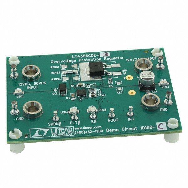
ispPAC-POWR6AT6 Data Sheet 6.If transmitted device address matches ispPAC-POWR6AT6 address, the master completes the cycle by set- ting the I2C closed loop trim register SMBA bit low again. This releases the CLTLOCK/SMBA pin (it goes high). Figure 3-22. SMBAlert Bus Transaction SMBA SCL 1 2 3 4 5 6 7 8 9 1 2 3 4 5 6 7 8 9 SDA 0 0 0 1 1 0 0 R/W ACK A6 A5 A4 A3 A2 A1 A0 x ACK SLAVE START ALERT RESPONSE ADDRESS SLAVE ADDRESS (7 BITS) SLAVE STOP ASSERTS (0001 100) RELEASES SMBA SMBA Note: Shaded Bits Asserted by Slave After CLTLOCK/SMBA has been released, the bus master (typically a microcontroller) may opt to perform some service functions in which it may send data to or read data from the ispPAC-POWR6AT6. As part of the service functions, the bus master will typically need to clear whatever condition initiated the SMBAlert request (power sup- ply malfunction, etc.). For further information on the SMBus functionality, the user should consult the SMBus Stan- dard. Software-Based Design Environment Designers can configure the ispPAC-POWR6AT6 using PAC-Designer, an easy to use, Microsoft Windows compat- ible program. Circuit designs are entered graphically and then verified, all within the PAC-Designer environment. Full device programming is supported using PC parallel port I/O operations and a download cable connected to the serial programming interface pins of the ispPAC-POWR6AT6. A library of configurations is included with basic solu- tions and examples of advanced circuit techniques are available on the Lattice web site for downloading. In addi- tion, comprehensive on-line and printed documentation is provided that covers all aspects of PAC-Designer operation. The PAC-Designer schematic window, shown in Figure 3-23, provides access to all configurable ispPAC- POWR6AT6 elements via its graphical user interface. All analog input and output pins are represented. Static or non-configurable pins such as power, ground, and the serial digital interface are omitted for clarity. Any element in the schematic window can be accessed via mouse operations as well as menu commands. When completed, con- figurations can be saved, simulated, and downloaded to devices. Figure 3-23. PAC-Designer ispPAC-POWR6AT6 Design Entry Screen 25
ispPAC-POWR6AT6 Data Sheet In-System Programming The ispPAC-POWR6AT6 is an in-system programmable device. This is accomplished by integrating all E2 configu- ration memory and control logic on-chip. Programming is performed through a 4-wire, IEEE 1149.1 compliant serial JTAG interface at normal logic levels. Once a device is programmed, all configuration information is stored on-chip, in non-volatile E2CMOS memory cells. The specifics of the IEEE 1149.1 serial interface and all ispPAC-POWR6AT6 instructions are described in the JTAG interface section of this data sheet. User Electronic Signature A user electronic signature (UES) feature is included in the E2CMOS memory of the ispPAC-POWR6AT6. This con- sists of 32 bits that can be configured by the user to store unique data such as ID codes, revision numbers or inven- tory control data. The specifics of this feature are discussed in the IEEE 1149.1 serial interface section of this data sheet. Electronic Security An electronic security “fuse” (ESF) bit is provided in every ispPAC-POWR6AT6 device to prevent unauthorized readout of the E2CMOS configuration bit patterns. Once programmed, this cell prevents further access to the func- tional user bits in the device. This cell can only be erased by reprogramming the device, so the original configura- tion cannot be examined once programmed. Usage of this feature is optional. The specifics of this feature are discussed in the IEEE 1149.1 serial interface section of this data sheet. Production Programming Support Once a final configuration is determined, an ASCII format JEDEC file can be created using the PAC-Designer soft- ware. Devices can then be ordered through the usual supply channels with the user’s specific configuration already preloaded into the devices. By virtue of its standard interface, compatibility is maintained with existing production programming equipment, giving customers a wide degree of freedom and flexibility in production planning. Evaluation Fixture The Design Kit for the ispPAC-POWR1220AT8, a larger device that contains all the same functions as the ispPAC- POWR6AT6, can be used to evaluate the ispPAC-POWR6AT6. Included in the basic ispPAC-POWR1220AT8 Design Kit is an engineering prototype board that can be connected to the parallel port of a PC using a Lattice download cable. It demonstrates proper layout techniques for the ispPAC-POWR1220AT8 which also apply to the ispPAC-POWR6AT6 and can be used in real time to check circuit operation as part of the design process. Input and output connections are provided to aid in the evaluation of either device for a given application. (Figure 3-24). Figure 3-24. Download from a PC PAC-Designer Software Other System C ircuitry ispDOWNLOAD Cable (6') 4 ispPAC-POWR 1220AT8 Device IEEE Standard 1149.1 Interface (JTAG) Serial Port Programming Interface Communication with the ispPAC-POWR6AT6 is facilitated via an IEEE 1149.1 test access port (TAP). It is used by the ispPAC-POWR6AT6 as a serial programming interface. A brief description 26
ispPAC-POWR6AT6 Data Sheet of the ispPAC-POWR6AT6 JTAG interface follows. For complete details of the reference specification, refer to the publication, Standard Test Access Port and Boundary-Scan Architecture, IEEE Std 1149.1-1990 (which now includes IEEE Std 1149.1a-1993). Overview An IEEE 1149.1 test access port (TAP) provides the control interface for serially accessing the digital I/O of the isp- PAC-POWR6AT6. The TAP controller is a state machine driven with mode and clock inputs. Given in the correct sequence, instructions are shifted into an instruction register, which then determines subsequent data input, data output, and related operations. Device programming is performed by addressing the configuration register, shifting data in, and then executing a program configuration instruction, after which the data is transferred to internal E2CMOS cells. It is these non-volatile cells that store the configuration or the ispPAC-POWR6AT6. A set of instruc- tions are defined that access all data registers and perform other internal control operations. For compatibility between compliant devices, two data registers are mandated by the IEEE 1149.1 specification. Others are func- tionally specified, but inclusion is strictly optional. Finally, there are provisions for optional data registers defined by the manufacturer. The two required registers are the bypass and boundary-scan registers. Figure 3-25 shows how the instruction and various data registers are organized in an ispPAC-POWR6AT6. Figure 3-25. ispPAC-POWR6AT6 TAP Registers CFG_DATA REGISTER (56 BITS) E2CMOS NON-VOLATILE MEMORY CFG_ADDRESS REGISTER (5 BITS) R XE UES REGISTER (32 BITS) E L P TI L IDCODE REGISTER (32 BITS) U M BYPASS REGISTER (1 BIT) INSTRUCTION REGISTER (8 BITS) TEST ACCESS PORT (TAP) OUTPUT LOGIC LATCH TDI TCK TMS TDO TAP Controller Specifics The TAP is controlled by the Test Clock (TCK) and Test Mode Select (TMS) inputs. These inputs determine whether an Instruction Register or Data Register operation is performed. Driven by the TCK input, the TAP consists of a small 16-state controller design. In a given state, the controller responds according to the level on the TMS input as shown in Figure 3-26. Test Data In (TDI) and TMS are latched on the rising edge of TCK, with Test Data Out (TDO) becoming valid on the falling edge of TCK. There are six steady states within the controller: Test-Logic- Reset, Run- Test/Idle, Shift-Data-Register, Pause-Data-Register, Shift-Instruction-Register and Pause-Instruction- Register. But there is only one steady state for the condition when TMS is set high: the Test-Logic-Reset state. This allows a reset of the test logic within five TCKs or less by keeping the TMS input high. Test-Logic-Reset is the power-on default state. 27
ispPAC-POWR6AT6 Data Sheet Figure 3-26. TAP States 1 Test-Logic-Rst 0 1 1 1 0 Run-Test/Idle Select-DR-Scan Select-IR-Scan 0 0 1 1 Capture-DR Capture-IR 0 0 Shift-DR 0 Shift-IR 0 1 1 1 1 Exit1-DR Exit1-IR 0 0 Pause-DR 0 Pause-IR 0 1 1 0 0 Exit2-DR Exit2-IR 1 1 Update-DR Update-IR 1 0 1 0 Note: The value shown adjacent to each state transition in this figure represents the signal present at TMS at the time of a rising edge at TCK. When the correct logic sequence is applied to the TMS and TCK inputs, the TAP will exit the Test-Logic-Reset state and move to the desired state. The next state after Test-Logic-Reset is Run-Test/Idle. Until a data or instruction shift is performed, no action will occur in Run-Test/Idle (steady state = idle). After Run-Test/Idle, either a data or instruc- tion shift is performed. The states of the Data and Instruction Register blocks are identical to each other differing only in their entry points. When either block is entered, the first action is a capture operation. For the Data Regis- ters, the Capture-DR state is very simple: it captures (parallel loads) data onto the selected serial data path (previ- ously chosen with the appropriate instruction). For the Instruction Register, the Capture-IR state will always load the IDCODE instruction. It will always enable the ID Register for readout if no other instruction is loaded prior to a Shift-DR operation. This, in conjunction with mandated bit codes, allows a “blind” interrogation of any device in a compliant IEEE 1149.1 serial chain. From the Capture state, the TAP transitions to either the Shift or Exit1 state. Normally the Shift state follows the Capture state so that test data or status information can be shifted out or new data shifted in. Following the Shift state, the TAP either returns to the Run-Test/Idle state via the Exit1 and Update states or enters the Pause state via Exit1. The Pause state is used to temporarily suspend the shifting of data through either the Data or Instruction Register while an external operation is performed. From the Pause state, shifting can resume by reentering the Shift state via the Exit2 state or be terminated by entering the Run-Test/Idle state via the Exit2 and Update states. If the proper instruction is shifted in during a Shift-IR operation, the next entry into Run-Test/Idle initiates the test mode (steady state = test). This is when the device is actually programmed, erased or verified. All other instructions are executed in the Update state. Test Instructions Like data registers, the IEEE 1149.1 standard also mandates the inclusion of certain instructions. It outlines the function of three required and six optional instructions. Any additional instructions are left exclusively for the manu- facturer to determine. The instruction word length is not mandated other than to be a minimum of two bits, with only the BYPASS and EXTEST instruction code patterns being specifically called out (all ones and all zeroes respec- tively). The ispPAC-POWR6AT6 contains the required minimum instruction set as well as one from the optional instruction set. In addition, there are several proprietary instructions that allow the device to be configured and ver- ified. Table 3-7 lists the instructions supported by the ispPAC-POWR6AT6 JTAG Test Access Port (TAP) controller: 28
ispPAC-POWR6AT6 Data Sheet Table 3-7. ispPAC-POWR6AT6 TAP Instruction Table Instruction Command Code Comments EXTEST 0000 0000 External Test - Defaults to BYPASS BULK_ERASE 0000 0011 Bulk erase device PROGRAM_SECURITY 0000 1001 Program security fuse DISCHARGE 0001 0100 Fast VPP discharge PROGRAM_ENABLE 0001 0101 Enable program mode IDCODE 0001 0110 Read contents of manufacturer ID code (32 bits) UES_READ 0001 0111 Read contents of UES register from E2CMOS (32 bits) UES_PROGRAM 0001 1010 Program UES bits into E2CMOS SAMPLE 0001 1100 Sample/Preload - Defaults to BYPASS PROGRAM_DISABLE 0001 1110 Disable program mode Resets device (refer to reset command via JTAG or I2C section of this data RESET 0010 0010 sheet) ERASE_DONE_BIT 0010 0100 Erases the DONE bit only CFG_VERIFY 0010 1000 Verify the configuration data CFG_ERASE 0010 1001 Erase just the configuration data CFG_ADDRESS 0010 1011 Select the configuration address register (4 bits) CFG_DATA_SHIFT 0010 1101 Configuration data shift (56 bits) CFG_PROGRAM 0010 1110 Program configuration data PROGRAM_DONE_BIT 0010 1111 Programs the DONE bit BYPASS 1111 1111 Bypass - Connect TDO to TDI BYPASS is one of the three required JTAG instructions. It selects the Bypass Register to be connected between TDI and TDO and allows serial data to be transferred through the device without affecting the operation of the ispPACPOWR6AT6. The IEEE 1149.1 standard defines the bit code of this instruction to be all ones (111111). The required SAMPLE/ PRELOAD instruction dictates the Boundary-Scan Register be connected between TDI and TDO. The ispPAC- POWR6AT6 has no boundary scan register, so for compatibility it defaults to the BYPASS mode whenever this instruction is received. The bit code for this instruction is defined by Lattice as shown in Table 3-7. The EXTEST (external test) instruction is required and would normally place the device into an external boundary test mode while also enabling the boundary scan register to be connected between TDI and TDO. Again, since the ispPAC-POWR6AT6 has no boundary scan logic, the device is put in the BYPASS mode to ensure specification compatibility. The bit code of this instruction is defined by the 1149.1 standard to be all zeros (000000). The optional IDCODE (identification code) instruction is incorporated in the ispPAC-POWR6AT6 and leaves it in its functional mode when executed. It selects the Device Identification Register to be connected between TDI and TDO. The Identification Register is a 32-bit shift register containing information regarding the IC manufacturer, device type and version code (Figure 3-27). Access to the Identification Register is immediately available, via a TAP data scan operation, after power-up of the device, or by issuing a Test-Logic-Reset instruction. The bit code for this instruction is defined by Lattice as shown in Table 3-7. 29
ispPAC-POWR6AT6 Data Sheet Figure 3-27. ispPAC-POWR6AT6 ID Code MSB LSB XXXX / 0000 0001 1000 0000 / 0000 0100 001 / 1 Part Number (16 bits) JEDEC Manufacturer 0180h = ispPAC-POWR6AT6 Identity Code for Lattice Semiconductor Version (11 bits) Constant 1 (4 bits) E2 Configured (1 bit) per 1149.1-1990 ispPAC-POWR6AT6 Specific Instructions There are 15 unique instructions specified by Lattice for the ispPAC-POWR6AT6. These instructions are primarily used to interface to the various user registers and the E2CMOS non-volatile memory. Additional instructions are used to control or monitor other features of the device. A brief description of each unique instruction is provided in detail below, and the bit codes are found in Table 3-7. BULK_ERASE - This instruction will bulk erase the ispPAC-POWR6AT6. The action occurs at the second rising edge of TCK in Run-Test-Idle JTAG state. The device must already be in programming mode (PROGRAM_ENABLE instruction). PROGRAM_SECURITY - This instruction is used to program the electronic security fuse (ESF) bit. Programming the ESF bit protects proprietary designs from being read out. The programming occurs at the second rising edge of the TCK in Run-Test-Idle JTAG state. The device must already be in programming mode (PROGRAM_ENABLE instruction). DISCHARGE - This instruction is used to discharge the internal programming supply voltage after an erase or pro- gramming cycle and prepares ispPAC-POWR6AT6 for a read cycle. PROGRAM_ENABLE - This instruction enables the programming mode of the ispPAC-POWR6AT6. IDCODE - This instruction connects the output of the Identification Code Data Shift (IDCODE) Register to TDO (Figure 3-28), to support reading out the identification code. Figure 3-28. IDCODE Register TDO Bit Bit Bit Bit Bit Bit Bit Bit Bit Bit 31 30 29 28 27 4 3 2 1 0 UES_READ - This instruction both reads the E2CMOS bits in the UES register and places the UES register between the TDI and TDO pins (as shown in Figure 3-29), to support programming or reading of the user electronic signature bits. Figure 3-29. UES Register TDO Bit Bit Bit Bit Bit Bit Bit Bit Bit Bit 15 14 13 12 11 4 3 2 1 0 UES_PROG - This instruction will program the content of the UES Register into the UES E2CMOS memory. The device must already be in programming mode (PROGRAM_ ENABLE instruction). PROGRAM_DISABLE - This instruction disables the programming mode of the ispPAC-POWR6A6. The Test- Logic-Reset JTAG state can also be used to cancel the programming mode of the ispPAC-POWR6A6. 30
ispPAC-POWR6AT6 Data Sheet RESET - This command resets the ispPAC-POWR6AT6 to a condition near that of the power-on reset state (refer to reset command via JTAG or I2C section of this data sheet for more details and known exceptions). ERASE_DONE_BIT - This instruction erases the ispPAC-POWR6A6 DONE bit. CFG_VERIFY - This instruction is used to verify the contents of the selected configuration array column. This spe- cific column is preselected by using CFG_ADDRESS instruction. CFG_ERASE - This instruction will bulk erase the configuration array. The action occurs at the second rising edge of TCK in Run-Test-Idle JTAG state. The device must already be in programming mode (PROGRAM_ENABLE instruction). CFG_ADDRESS - This instruction is used to set the address of the configuration array for subsequent program or read operations. CFG_DATA_SHIFT - This instruction is used to shift data into the configuration register prior to programming or reading. CFG_PROGRAM - This instruction programs the selected configuration array column. This specific column is pre- selected by using CFG_ADDRESS instruction. The programming occurs at the second rising edge of the TCK in Run-Test-Idle JTAG state. The device must already be in programming mode (PROGRAM_ENABLE instruction). PROGRAM_DONE_BIT - This instruction programs the ispPAC-POWR6A6 DONE bit. Note: Before any of the above programming instructions are executed, the respective E2CMOS bits need to be erased using the corresponding erase instruction 31
ispPAC-POWR6AT6 Data Sheet Package Diagrams 32-Pin QFNS Dimensions in millimeters 2X 0.15 C A A D D2 PIN #1 ID FIDUCIAL 3 LOCATED IN THIS AREA 2X L N 0.15 C B 32X N 1 1 3 PIN 1 ID AREA E E2 B e TOP VIEW b 0.10 M C A B 4 0.50 TYP BOTTOM VIEW 4X VIEW A VIEW A A C SIDE VIEW 0.08 C 5 SEATING PLANE A1 A3 SYMBOL MIN. NOM. MAX. NOTES: UNLESS OTHERWISE SPECIFIED A 0.80 0.90 1.00 1. DIMENSIONS AND TOLERANCES A1 0.00 0.02 0.05 PER ANSI Y14.5M. A3 0.2 REF 2. ALL DIMENSIONS ARE IN MILLIMETERS. D 5.0 BSC EXACT SHAPE AND SIZE OF THIS D2 1.25 2.70 3.75 3 FEATURE IS OPTIONAL. E 5.0 BSC DIMENSION b APPLIES TO PLATED E2 1.25 2.70 3.75 4 TERMINAL AND IS MEASURED BETWEEN b 0.18 0.24 0.30 0.15 AND 0.30 mm FROM TERMINAL TIP. e 0.50 BSC 5 APPLIES TO EXPOSED PORTION OF TERMINALS. L 0.30 0.40 0.50 32
ispPAC-POWR6AT6 Data Sheet 32-Pin QFN1 Dimensions in millimeters 2X 0.25 C A A 5.00 4 b 0.10 M C A B 4.75 D2 2X PIN #1 ID FIDUCIAL N 0.25 C B N LOCATED IN THIS AREA 3 1 1 PIN 1 ID 4.75 5.00 E2 L 32X DIEPAD 0.20 C B (EXPOSED BACKSIDE) 2X B e 3 TOP VIEW 0.20 C A 3.5 2X 4X 0 BOTTOM VIEW A2 A C 5 0.08 C SIDE VIEW A3 A1 SEATING PLANE Note: If soldered to the circuit board for thermal considerations, insure the thermal pad is connected electrically to ground. Otherwise, the thermal pad should not be connected electrically (must be left "floating"). For important information on the preferred mounting of QFN packages, refer to the following application note at: http://www.amkor.com/products/notes_papers/MLFAppNote.pdf. SYMBOL MIN. NOM. MAX. NOTES: UNLESS OTHERWISE SPECIFIED A - 0.85 1.00 1. DIMENSIONS AND TOLERANCES A1 0.00 0.01 0.05 PER ANSI Y14.5M. A2 0.00 0.65 1.00 2. ALL DIMENSIONS ARE IN MILLIMETERS. A3 0.20 REF EXACT SHAPE AND SIZE OF THIS D2 1.25 2.70 3.25 3 FEATURE IS OPTIONAL. E2 1.25 2.70 3.25 DIMENSION b APPLIES TO PLATED 4 TERMINAL AND IS MEASURED BETWEEN e 0.50 BSC 0.20 AND 0.25 mm FROM TERMINAL TIP. b 0.18 0.24 0.30 5 APPLIES TO EXPOSED PORTION OF TERMINALS. L 0.30 0.40 0.50 0 - - 12 1. Use 32-pin QFNS package for all new designs. Refer to PCN #13A-08 for 32-pin QFN package discontinuance. 33
ispPAC-POWR6AT6 Data Sheet Part Number Description ispPAC-P OWR6 AT 6 - 01X X32X Device Family Operating Temperature Range I = Industrial (-40oC to +85oC) Device Number Package S32 = 32-pin QFNS1, 3 SN32 = Lead-Free 32-pin QFNS N32 = 32-pin QFN2 NN32 = Lead-Free 32-pin QFN2 Performance Grade 01 = Standard 1. Contact factory for package availability. 2. Use 32-pin QFNS package for all new designs. Refer to PCN #13A-08 for 32-pin QFN package discontinuance. 3. Use SN 32-pin QFNS package for all new designs. Refer to PCN #11A-13 for S32QFNS package discontinuance. Ordering Information Lead-Free Packaging Part Number Package Pins ispPAC-POWR6AT6-01SN32I QFNS 32 34
ispPAC-POWR6AT6 Data Sheet Package Options 6 1 2 3 4 5 6 N D M M M M M M O N RI RI RI RI RI RI M G T T T T T T V 32 31 30 29 28 27 26 25 TDO 1 NC 24 VMON6GS Die Pad VCCJ 2 23 VMON5 TCK 3 22 VMON5GS TDI 4 21 VMON4 ispPAC-POWR6AT6 32-Pin QFNS TMS 5 20 VMON4GS CLTENb 6 19 VMON3 VPS0 7 18 VMON3GS VPS1 8 17 VMON2 9 10 11 12 13 14 15 16 A L A D A S 1 S B C D C C G N G M S S C C 1 O 2 OCK/S V V VMON VM VMON L T L C Technical Support Assistance e-mail: isppacs@latticesemi.com Internet: www.latticesemi.com Revision History Date Version Change Summary April 2006 01.0 Initial release. October 2006 01.1 Data sheet status changed to “Final.” Increased Max DAC output current to +/- 200 µA. Included V and V specifications for I2C interface. IL IH April 2007 01.2 References to Die Pad added to Pin Descriptions table, Recommended Operating Condi- tions table and Package Options diagram. December 2008 01.3 Added 32-pin QFNS package Ordering Part Number information per PCN #13A-08. September 2013 01.4 Updated voltage range for TADC Error. Updated corporate logo. Updated Technical Support Assistance information. November 2013 01.5 Updated 32-pin QFNS Package Ordering Part Number information per PCN #11A-13. 35