ICGOO在线商城 > ISL6224CAZ
 Datasheet下载
- 型号: ISL6224CAZ
- 制造商: Intersil
- 库位|库存: xxxx|xxxx
- 要求:
| 数量阶梯 | 香港交货 | 国内含税 |
| +xxxx | $xxxx | ¥xxxx |
查看当月历史价格
查看今年历史价格
ISL6224CAZ产品简介:
ICGOO电子元器件商城为您提供ISL6224CAZ由Intersil设计生产,在icgoo商城现货销售,并且可以通过原厂、代理商等渠道进行代购。 提供ISL6224CAZ价格参考以及IntersilISL6224CAZ封装/规格参数等产品信息。 你可以下载ISL6224CAZ参考资料、Datasheet数据手册功能说明书, 资料中有ISL6224CAZ详细功能的应用电路图电压和使用方法及教程。
ISL6224CAZ 是瑞萨电子(Renesas Electronics America Inc.)推出的双路同步降压DC-DC开关控制器,专为高性能便携式计算设备设计。其典型应用场景包括:笔记本电脑、超轻薄本(Ultrabook)、嵌入式工控主板及高端平板电脑的CPU核心供电(VCORE)系统。该芯片支持双相并联控制,可驱动外置MOSFET,提供高达25A的总输出电流,具备精确的电压调节(±0.8%精度)、快速动态响应和自适应电压定位(AVP)功能,满足Intel移动处理器(如Core i系列)对VID动态调压与节能状态(C-states)的严格要求。此外,它集成过流、过压、欠压及热保护机制,支持PSI#(Power State Indicator)信号与系统电源管理IC协同实现深度睡眠模式下的低功耗控制。因采用无铅QFN-32封装及宽输入电压范围(5.5V–25V),亦适用于多电池供电或适配器兼容的工业便携设备电源设计。需注意:ISL6224CAZ为控制器(非集成MOSFET的PMIC),须搭配外部功率器件使用,强调设计灵活性与效率优化。
| 参数 | 数值 |
| 产品目录 | 集成电路 (IC) |
| Cuk | 无 |
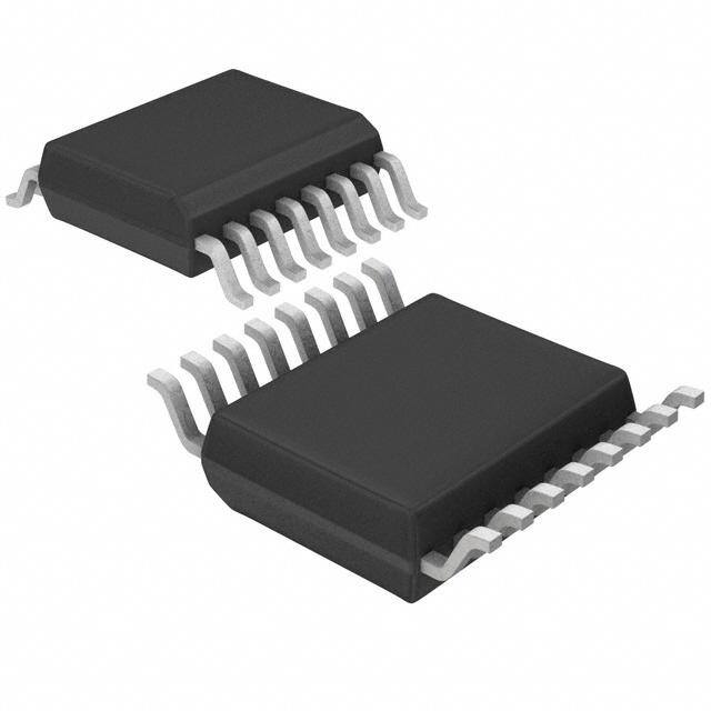
| 描述 | IC REG CTRLR BUCK PWM CM 16-SSOP |
| 产品分类 | |
| 品牌 | Intersil |
| 数据手册 | |
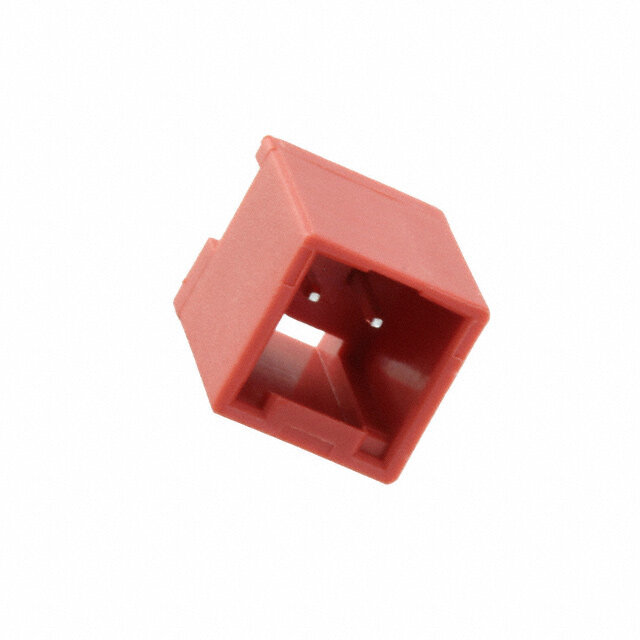
| 产品图片 |
|
| 产品型号 | ISL6224CAZ |
| PWM类型 | 电流模式 |
| rohs | 无铅 / 符合限制有害物质指令(RoHS)规范要求 |
| 产品系列 | - |
| 产品目录页面 | |
| 倍增器 | 无 |
| 分频器 | 无 |
| 包装 | 管件 |
| 升压 | 无 |
| 占空比 | 94% |
| 反向 | 无 |
| 反激式 | 无 |
| 封装/外壳 | 16-SSOP(0.154",3.90mm 宽) |
| 工作温度 | -10°C ~ 85°C |
| 标准包装 | 98 |
| 电压-电源 | 4.75 V ~ 5.25 V |
| 输出数 | 1 |
| 降压 | 是 |
| 隔离式 | 无 |
| 频率-最大值 | 690kHz |


- 商务部:美国ITC正式对集成电路等产品启动337调查
- 曝三星4nm工艺存在良率问题 高通将骁龙8 Gen1或转产台积电
- 太阳诱电将投资9.5亿元在常州建新厂生产MLCC 预计2023年完工
- 英特尔发布欧洲新工厂建设计划 深化IDM 2.0 战略
- 台积电先进制程称霸业界 有大客户加持明年业绩稳了
- 达到5530亿美元!SIA预计今年全球半导体销售额将创下新高
- 英特尔拟将自动驾驶子公司Mobileye上市 估值或超500亿美元
- 三星加码芯片和SET,合并消费电子和移动部门,撤换高东真等 CEO
- 三星电子宣布重大人事变动 还合并消费电子和移动部门
- 海关总署:前11个月进口集成电路产品价值2.52万亿元 增长14.8%


PDF Datasheet 数据手册内容提取
ISL6224 NOc1No-T8nO 8Rt a8ERc-CIEtN OCoTOuMErMRM TSMEeIcNELhDN onEDri cDEwa DwFl SORwuRE.ipn PNptLeoEArrWstC iC lED.ceMEonESmteNIG/rtT sNactS DATASHEET FN9042 Single Output Mobile-Friendly PWM Controller Rev 8.00 June 8, 2006 The ISL6224 provides power control and protection for a single, Features adjustable output voltage required to power chip-sets and • Adjustable output voltgage: 0.9-5.5V memory banks in high-performance notebooks and PDAs. This output voltage is adjustable in the range from 0.9-5.5V. • High efficiency over wide load range - Higher efficiency in hysteretic mode at light load The hysteretic or PWM controller regulates the output voltage from battery voltages ranging from 4V to 24V. • Lossless current sense scheme Synchronous rectification and hysteretic operation at light - Uses MOSFET’s rDS(ON) loads contribute to a high efficiency over a wide range of - Optional current sense method higher precision input voltages and loads. Efficiency is even further enhanced • Supply operation mode by using MOSFET’s rDS(ON) as a current sense component. Feed-forward ramp modulation, average current mode - Wide VIN range: 4V-24V control and internal feed-back compensation provide fast - Single 5V system rail and firm handling of transients when powering advanced • Input undervoltage lock-out on VCC pin (UVLO) chip sets. • Excellent dynamic response Two-stage conversion using system 5V voltage is possible at - Combined voltage feed-forward and current mode a higher frequency (600kHz) to minimize the output filter size. control The ISL6224 monitors the output voltage. A PGOOD (power • Power-good indicator good) signal is issued when soft-start is completed and the • 300/600kHz switching frequency output is within ±10% of the set point. • Thermal shut-down A built-in overvoltage protection prevents output voltage from going above 120% of the set point. Undervoltage • Pb-free plus anneal available (RoHS compliant) protection latches the chip off when the output drops below Applications 70% of its setting value after soft-start sequence is completed. The PWM controller’s overcurrent circuitry • Mobile PCs monitors the output current by sensing the voltage drop • Graphic cards across the lower MOSFET. If higher precision sense technique is required, an optional external current-sense • Hand-held portable instruments resistor may be used. Related Literature Ordering Information • Application Note AN9983 PART PART PKG. Pinout NUMBER MARKING TEMP. (°C) PACKAGE DWG. # ISL6224 (SSOP) ISL6224CA ISL6224CA -10 to 85 16 Ld SSOP M16.15A TOP VIEW ISL6224CAZ 6224CAZ -10 to 85 16 Ld SSOP M16.15A (Note 1) (Pb-free) VIN 1 16 FCCM NOTES: PGOOD 2 15 BOOT 1. Intersil Pb-free plus anneal products employ special Pb-free EN 3 14 UGATE material sets; molding compounds/die attach materials and OCSET 4 13 PHASE 100% matte tin plate termination finish, which are RoHS compliant and compatible with both SnPb and Pb-free soldering VOUT 5 12 ISEN operations. Intersil Pb-free products are MSL classified at VSEN 6 11 VCC Pb-free peak reflow temperatures that meet or exceed the Pb-free requirements of IPC/JEDEC J STD-020. SOFT 7 10 LGATE 2. Add “-T” for Tape and Reel. GND 8 9 PGND FN9042 Rev 8.00 Page 1 of 13 June 8, 2006
ISL6224 Absolute Maximum Ratings Thermal Information Bias Voltage, VCC. . . . . . . . . . . . . . . . . . . . . . . . . . . . . .-0.3V to +7V Thermal Resistance (Typical, Note 1) JA (°C/W) Input Voltage, Vin . . . . . . . . . . . . . . . . . . . . . . . . . . . . . . . . . . +27.0V SSOP Package. . . . . . . . . . . . . . . . . . . . . . . . . . . . 112 Phase and Isen Pins. . . . . . . . . . . . . . . . . . . . .GND -0.3V to +29.0V Maximum Junction Temperature (Plastic Package) . . . . . . . .150°C BOOT and Ugate Pins . . . . . . . . . . . . . . . . . . . . . . . . . . . . . . . . + 32.0V Maximum Storage Temperature Range. . . . . . . . . . .-65°C to 150°C BOOT with respect to PHASE. . . . . . . . . . . . . . . . . . . . . . . . . .+ 7.0V Maximum Lead Temperature (Soldering 10s) . . . . . . . . . . . . .300°C All other pins . . . . . . . . . . . . . . . . . . . . . . . . . . . . GND -0.3V to 15V (SSOP - Lead Tips Only) ESD Classification. . . . . . . . . . . . . . . . . . . . . . . . . . . . . . . . .Class 2 Recommended Operating Conditions Bias Voltage, VCC. . . . . . . . . . . . . . . . . . . . . . . . . . . . . . .+5.0V ±5% Input Voltage, Vin . . . . . . . . . . . . . . . . . . . . . . . . . . . .4.0V to +24.0V Ambient Temperature Range. . . . . . . . . . . . . . . . . . . .-10°C to 85°C Junction Temperature Range. . . . . . . . . . . . . . . . . . .-10°C to 125°C CAUTION: Stresses above those listed in “Absolute Maximum Ratings” may cause permanent damage to the device. This is a stress only rating and operation of the device at these or any other conditions above those indicated in the operational sections of this specification is not implied. NOTE: 3. JA is measured with the component mounted on a high effective thermal conductivity test board in free air. See Tech Brief TB379 for details. Electrical Specifications Operating Conditions: VCC = 5V, TA = 10°C to 85°C, Unless Otherwise Noted. PARAMETER SYMBOL TEST CONDITIONS MIN TYP MAX UNITS VCC SUPPLY Bias Current ICC LGATE, UGATE Open, VSEN forced above - 850 1300 A regulation point Shutdown Current ICCSN - 5 15 A VCC UVLO Rising Vcc Threshold 4.3 - 4.75 V Falling Vcc Threshold 4.1 - 4.5 V Vcc UVLO Hysteris 0.1 - 0.5 V VIN Input Voltage Pin Current (Sink) IVIN VIN pin connected to the input voltage source 10 20 30 A Input Voltage Pin Current (Source) IVIN VIN pin connected to ground -7 -15 -20 A Shutdown Current IVIN - - 1 A OSCILLATOR PWM Oscillator Frequency Fc1 VIN = 3.5V - 24V 255 300 345 kHz PWM Oscillator Frequency Fc2 VIN 0.5V 510 600 690 kHz Ramp Amplitude, pk-pk VR1 VIN = 16V, By Design - 2 - V Ramp Amplitude, pk-pk VR2 VIN 5V, By Design - 1.25 - V Ramp Offset VROFF - 0.5 - V REFERENCE AND SOFT-START Internal Reference Voltage VREF - 0.9 - V Reference Voltage Accuracy -1.0 - +1.0 % Soft-Start Current During Start-up ISOFT - 5 - A Soft-Start Threshold VSOFT - 1.5 - V PWM CONVERTER Load Regulation 0.0mA < IVOUT1 < 3.0A; 5.0V < VIN < 24.0V -1.0 - +1.0 % VSEN pin bias current IVSEN - 80 - nA FN9042 Rev 8.00 Page 2 of 13 June 8, 2006
ISL6224 Electrical Specifications Operating Conditions: VCC = 5V, TA = 10°C to 85°C, Unless Otherwise Noted. (Continued) PARAMETER SYMBOL TEST CONDITIONS MIN TYP MAX UNITS VOUT pin input impedance IVOUT 40 55 65 k Undervoltage Shutdown Level VUV1 Fraction of the set point; ~3s noise filter 70 - 80 % Overvoltage Protection VOVP1 Fraction of the set point; ~1s noise filter 113 - 120 % PWM CONTROLLER GATE DRIVERS Upper Drive Pull-Up Resistance R2UGPUP - 8 15 Upper Drive Pull-Down Resistance R2UGPDN - 3.2 5 Lower Drive Pull-Up Resistance R2LGPUP - 8 15 Lower Drive Pull-Down Resistance R2LGPDN - 1.5 2.4 POWER GOOD AND CONTROL FUNCTIONS Power-Good Lower Threshold VPG- Fraction of the set point; ~3s noise filter -14 - -8 % Power-Good Higher Threshold VPG+ Fraction of the set point; ~3s noise filter 10 - 15 % PGOOD Leakage Current IPGLKG VPULLUP = 5.5V - - 1 A PGOOD Voltage Low IPGOOD = -4mA - - 0.5 V EN - Low (Off) - - 0.8 V EN - High (On) 2.0 - - V FCCM -Hysteretic Operation Enabled - Vcc/2 - V FN9042 Rev 8.00 Page 3 of 13 June 8, 2006
JuFN Functional Block Diagram IS ne 8904 L622 , 22 4 0R 0e FCCM 6v 8 VIN VCC .0 GND BOOT 0 HGDR1 UGATE FCCM HI POWER-ON SHUTOFF PHASE FSET CLK RAMP RESET (POR) GATE LOGIC GATE CLK POR CONTROL DEADT VCC PWM/HYST LGDR POR PWM ON LGATE LO EN HYST ON OVP PGND SDWN REFERENCE HYST COMP1 REF AND - SOFT SOFT-START CLK1 + OC COMP1 PWM VCC OC LOGIC1 - LATCH 1 + EA1 Q D - R + VSEN + Q < VOLT- REF- OUTPUT - SECOND VOLTAGE + CLAMP +- MODE CHANGE COMP MONITOR FFBK LGATE LGATE1 R1=20K ISEN PGOOD - + PWM/HYS LOGIC OCSET VOUT P a g e 4 o f 1 3
ISL6224 Functional Pin Description GND (Pin 8) Signal ground for the IC. VIN (Pin 1) Provides battery voltage to the oscillator for feed-forward PGND (Pin 9) rejection of the input voltage variation. Also, this pin This is the power ground connection for PWM converter. programs frequency of the internal clock and gain of the This pin is connected to the lower MOSFET’s source ramp generator. When connected to the battery, which terminal. voltage varies from 4V to 24V, the clock frequency is set to LGATE (Pin 10) 300kHz and the ramp gain is set accordingly to accommodate the wide input voltage range. This pin provides the gate drive for the lower MOSFET. For two step conversion from the system 5V power rail, the VCC (Pin 11) Vin pin is connected to ground via a 150k resistor. This This pin provides power to the chip. arrangement changes the gain of the ramp generator to ISEN (Pin 12) accommodate the lower input voltage but does not change the clock frequency. This pin is used to monitor the voltage drop across the lower MOSFET for current feedback and overcurrent protection. When the Vin pin is connected to ground, the clock For precise current detection this input can be connected to frequency is set to 600kHz. The ramp generator gain is also an optional current sense resistor placed in series with the changed accordingly. This circuit arrangement enables the source of the lower MOSFET. designer to choose smaller output filter components. PHASE (Pin 13) PGOOD (Pin 2) Connect this pin to the PHASE node of the converter. The PGOOD is an open collector output used to indicate the PHASE node is the junction point of the upper MOSFET status of the output voltage. This pin is pulled high when the source, output filter inductor, and lower MOSFET drain. system output is within 10%of its respective nominal voltage. UGATE (Pin 14) This pin provides the gate drive for the upper MOSFET. EN (Pin 3) This pin provides the enable/disable function for the chip. The BOOT (Pin 15) IC is enabled when this pin is pulled over 2V or left open. This pin powers the upper MOSFET drivers of the PWM Note: a pulldown resistance of 100kor less is required to converter. Connect this pin to the junction of bootstrap disable the controller. capacitor with the cathode of the bootstrap diode. Anode of the bootstrap diode is connected to the VCC pin. OCSET (Pin 4) A resistor from this pin to GND sets the overcurrent FCCM (Pin 16) protection threshold. This pin, when pulled to VCC, restrains hysteretic operation in light loads. VOUT (Pin 5) This pin is used for feedback of the output voltage to General Description properly position output voltage during operational mode Operational Overview change. The ISL6224 is a single-channel PWM controller intended VSEN (Pin 6) for chipset, DRAM, or other low voltage power needs of This pin is connected to the output via a resistive divider and modern notebook and sub-notebook PCs. The IC integrates provides the voltage feedback signal for the PWM controller. control circuits and feedback compensation for a single The PGOOD, UVP, and OVP circuits use this signal to report synchronous buck converter. The output voltage is set in the output voltage status. range of 0.9–5.5V by an external resistive divider. SOFT (Pin 7) The synchronous buck converter can be configured for either 300kHz or 600kHz switching frequencies. When This pin provides soft-start of the PWM controller. When the operated from battery, a switching frequency of 300kHz is EN pin is pulled high, the voltage on the capacitor connected recommended. When operating from 5V, switching to the soft-start pin is rising linearly due to the 5A pull-up frequencies of 300kHz or 600kHz are an option. For 300kHz current. The output voltage follows the voltage on the operation, pin 1 should be connected through a resistor capacitor until it reaches the value of 0.9V. The further rise of (150K) to gnd. For 600kHz operation, pin 1 should simply be the voltage on the soft-start capacitor does not affect the output voltage. FN9042 Rev 8.00 Page 5 of 13 June 8, 2006
ISL6224 grounded. Table 1. shows the configuration for different of this resistor can be obtained from the following modes of operation. Figure 1 below shows plots of the ramp expression: speed compensation. 11Risen Rocset = --------------------------------- 300kHz CLOCK IocRdson 600kHz CLOCK Vint Vint where Ioc is the value of overcurrent. The resulting current ------------- ------------- Vint 2 T 4 T ----8------T--- out of the ISEN pin through RISEN, is used for current Vo/4 feedback and current limit protection. This is compared with an internal current limit threshold. When a sampled value of Vo/8 the output current is determined to be above the current limit threshold, the PWM drive is terminated and a counter is FIGURE 1. RAMP SPEED COMPENSATION Vo = 2.5V initiated. This limits the inductor current build-up and essentially switches the converter into current-limit mode. If an overcurrent is detected between 26ms to 53ms later, an TABLE 1. CONFIGURATION FOR MODES OF OPERATION overcurrent shutdown is initiated. If during the 26ms to 53ms OPERATION PIN 1 CONNECTION PIN 1 POTENTIAL period, an overcurrent is not detected, the counter is reset One-stage 300kHz Vin V1 > 4V and sampling continues as normal. Two-stage 300kHz 150K-GND 1V < V1 < 2V This current limit scheme has proven to be very robust in Two-stage 600kHz GND V1 < 0.5V applications like portable computers where fast inductor current build-up is common due to a large difference The synchronous converter light-load efficiency is enhanced between input and output voltages and a low value of the by a hysteretic mode of operation which is automatically inductor. engaged at light loads when the inductor current becomes Light-Load (Hysteretic) Operation discontinuous. As the filter inductor resumes continuous current, the PWM mode of operation is automatically In the light-load (hysteretic) mode the output voltage is restored. regulated by the hysteretic comparator which regulates the output voltage by maintaining the output voltage ripple as The ISL6224 control IC employs an average current mode shown in Figure 2. In hysteretic mode, the inductor current control scheme with input voltage feedforward ramp flows only when the output voltage reaches the lower limit of programming for better rejection of input voltage variations. the hysteretic comparator and turns off at the upper limit. Current Sensing and Current Limit Protection Hysteretic mode saves converter energy at light loads by supplying energy only at the time when the output voltage The PWM converter uses the lower MOSFET on-state requires it. This mode conserves energy by reducing the resistance, rDS(ON), as the current-sensing element. This power dissipation associated with continuous switching. technique eliminates the need for a current sense resistor and the associated power losses. If more accurate current During the time between inductor current pulses, both the protection is desired, current sense resistors may be used in upper and lower MOSFETs are turned off. This is referred to series with the lower MOSFET’s source. as ‘diode emulation mode’ because the lower MOSFET performs the function of a diode. This diode emulation mode A current proportional signal is used to provide average prevents the output capacitor from discharging through the current mode control and overcurrent protection. The gain in lower MOSFET when the upper MOSFET is not conducting. the current sense circuit is set by the resistor connected from ISEN (pin 12) to the PHASE node of the buck converter. The NOTE: the PWM only operation can intentionally be forced by tying value of this resistor can be estimated by the following pin 16, FCCM, to VCC. expression: IomaxRdson Risen = -------------------------------------------–100 75A where Iomax is the maximum inductor current. The value of RISEN should be specified for the expected maximum operating temperature. An overcurrent protection threshold is set by an external resistor connected from OCSET (pin 4) to ground. The value FN9042 Rev 8.00 Page 6 of 13 June 8, 2006
ISL6224 due to the voltage drop on the output capacitor ESR. If the VOUT decrease causes the output voltage to drop below the t hysteretic regulation level, the mode is changed to PWM on the next clock cycle. This insures the full power required by IL the increase in output current. t PHASE COMP 1 2 3 4 5 6 7 8 t IL t MODE PWM HYSTERETIC OF OPERATION t FIGURE 2. HYSTERETIC OPERATION MODE Operation-Mode Control The mode-control circuit changes the converter’s mode of PHASE NODE operation based on the voltage polarity of the phase node t when the lower MOSFET is conducting and just before the 1 2 3 4 5 6 7 8 upper MOSFET turns on. For continuous inductor current, PHASE the phase node is negative when the lower MOSFET is COMP t conducting and the converters operate in fixed-frequency PWM mode as shown in Figure 3. When the load current MODE PWM HYSTERETIC decreases to the point where the inductor current flows OF OPERATION t through the lower MOSFET in the ‘reverse’ direction, the FIGURE 3. MODE CONTROL WAVEFORMS phase node becomes positive, and the mode is changed to hysteretic. Gate Control Logic A phase comparator handles the timing of the phase node The gate control logic translates generated PWM control voltage sensing. A low level on the phase comparator output signals into the MOSFET gate drive signals providing indicates a negative phase voltage during the conduction necessary amplification, level shifting and shoot-through time of the lower MOSFET. A high level on the phase protection. Also, it has functions that help optimize the IC comparator output indicates a positive phase voltage. performance over a wide range of operational conditions. When the phase node is positive (phase comparator high), Since MOSFET switching time can vary dramatically from at the end of the lower MOSFET conduction time, for eight type to type and with the input voltage, the gate control logic consecutive clock cycles, the mode is changed to hysteretic provides adaptive dead time by monitoring the gate-to- as shown in Figure 3. The dashed lines indicate when the source voltages of both upper and lower MOSFETs. The phase node goes positive and the phase comparator output lower MOSFET is not turned on until the gate-to-source goes high. The solid vertical lines at 1,2,...8 indicate the voltage of the upper MOSFET has decreased to less than sampling time, of the phase comparator, to determine the approximately 1V. Similarly, the upper MOSFET is not turned polarity (sign) of the phase node. At the transition between on until the gate-to-source voltage of the lower MOSFET has PWM and hysteretic mode both the upper and lower decreased to less than approximately 1V. This allows a wide MOSFETs are turned off. The phase node will ‘ring’ based variety of upper and lower MOSFETs to be used without a on the output inductor and the parasitic capacitance on the concern for simultaneous conduction, or shoot-through. phase node and settle out at the value of the output voltage. The mode change from hysteretic to PWM can be caused by one of two events. One event is the same mechanism that causes a PWM to hysteretic transition. But instead of looking for eight consecutive positive occurrences on the phase node, it is looking for eight consecutive negative occurrences on the phase node. The operation mode will be changed from hysteretic to PWM when these eight consecutive pulses occur. This transition technique prevents jitter of the operation mode at load levels close to boundary. The other mechanism for changing from hysteretic to PWM is due to a sudden increase in the output current. This step load causes an instantaneous decrease in the output voltage FN9042 Rev 8.00 Page 7 of 13 June 8, 2006
ISL6224 Soft-Start Operation This ‘soft-crowbar’ and monitoring of the output, prevents the output voltage from ringing negative as the inductor current Soft-start of the Synchronous Buck Converter is flows in the ‘reverse’ direction through the lower MOSFET accomplished by means of a capacitor connected from pin 7, and output capacitors. SOFT to ground. The soft-start time can be obtained from the following equation: Component Selection Guidelines 1.5VCss Tss = ------------------------------ 5.0A Output Capacitor Selection The output capacitors have unique requirements. In general, Figure 4 shows the soft-start initiated by the ENABLE pin the output capacitors should be selected to meet the being pulled high with the VIN input at 5.6V and the resulting dynamic regulation requirements including ripple voltage 3.3V output and PGOOD signal. While the ENABLE pin is and load transients. held low, prior to t0, the output is off. When the EN pin is pulled high, at t0, the voltage on the capacitor connected to Selection of the output capacitors is also dependent on the the soft-start pin rises linearly due to the internal 5A current output inductor so some inductor analysis is required to source starts charging the capacitor. The output voltage select the output capacitors. follows the voltage on the capacitor till it reaches the value of One of the parameters limiting the converter’s response to a 0.9V at t1. At this moment, t1, the output voltage started load transient is the time required for the inductor current to regulation. The soft-start is complete when PGOOD pin is slew to its new level. Given a sufficiently fast control loop high at t2 and further rise of the voltage on the soft-start design, the ISL6224 will provide either 0% or 94% duty cycle capacitor does not affect the output voltage. in response to a load transient. The response time is the time interval required to slew the inductor current from an initial current value to the load current level. During this interval the difference between the inductor current and the transient current level must be supplied by the output capacitor(s). Minimizing the response time can minimize the output capacitance required. If the load transient rise time is slower than the inductor response time, as in a hard drive or CD drive, this reduces the requirement on the output capacitor. The maximum capacitor value required to provide the full, rising step, transient load current during the response time of the inductor is: L I I O TRAN TRAN C = ------------------------------------------------------------------ OUT V –V 2 DV IN OUT OUT Where: COUT is the output capacitor(s) required, LO is the t0 t1 t2 output inductor, ITRAN is the transient load current step, VIN FIGURE 4. MODE CONTROL WAVEFORMS is the input voltage, VOUT is output voltage, and DVOUT is the drop in output voltage allowed during the load transient. Power Good Status High frequency capacitors initially supply the transient The ISL6224 monitors the output voltage. A single power- current and slow the load rate-of-change seen by the bulk good signal, PGOOD, is issued when soft-start is completed capacitors. The bulk filter capacitor values are generally and the output is within 10% of it’s set point. After the soft- determined by the ESR (equivalent series resistance) and start sequence is completed, undervoltage protection voltage rating requirements as well as actual capacitance latches the chip off when any of the monitored outputs drop requirements. The output voltage ripple is due to the inductor below 70% of its set point. ripple current and the ESR of the output capacitors as defined by: A ‘soft-crowbar’ function is implemented for an overvoltage on the output. If the output voltage goes above 120% of its VRIPPLE = ILESR nominal output level, the upper MOSFET is turned off and the lower MOSFET is turned on. This ‘soft-crowbar’ where, I is calculated in the Inductor Selection section. L condition will be maintained until the output voltage returns High frequency decoupling capacitors should be placed as to the regulation window and then normal operation will close to the power pins of the load as physically possible. Be continue. careful not to add inductance in the circuit board wiring that FN9042 Rev 8.00 Page 8 of 13 June 8, 2006
ISL6224 could cancel the usefulness of these low inductance close to the upper MOSFET to suppress the voltage induced in components. Consult with the manufacturer of the load the parasitic circuit impedances. circuitry for specific decoupling requirements. For board designs that allow through-hole components, the Use only specialized low-ESR capacitors intended for Sanyo OS-CON® series offer low ESR and good temperature switching-regulator applications, at 300kHz, for the bulk performance. capacitors. In most cases, multiple electrolytic capacitors of For surface mount designs, solid tantalum capacitors can be small case size perform better than a single large case used, but caution must be exercised with regard to the capacitor. capacitor surge current rating. These capacitors must be The stability requirement on the selection of the output capable of handling the surge-current at power-up. The TPS capacitor is that the ‘ESR zero’, fZ, be between 1.2kHz and series available from AVX is surge current tested. 30kHz. This range is set by an internal, single compensation MOSFET Considerations zero at 6kHz. The ESR zero can be a factor of five on either side of the internal zero and still contribute to increased phase The logic level MOSFETs are chosen for optimum efficiency margin of the control loop. Therefore: given the potentially wide input voltage range and output power requirements. One dual N-Channel or two N-Channel 1 C = ------------------------------------------- OUT 2ESRf MOSFETs are used in each of the synchronous rectified buck Z converters for the outputs. These MOSFETs should be In conclusion, the output capacitors must meet three criteria: selected based upon rDS(ON), gate supply requirements, and thermal management considerations. 1. They must have sufficient bulk capacitance to sustain the output voltage during a load transient while the output The power dissipation includes two loss components; inductor current is slewing to the value of the load transient conduction loss and switching loss. These losses are 2. The ESR must be sufficiently low to meet the desired output distributed between the upper and lower MOSFETs according voltage ripple due to the output inductor current, and to duty cycle (see the following equations). The conduction losses are the main component of power dissipation for the 3. The ESR zero should be placed, in a rather large range, to provide additional phase margin. lower MOSFETs. Only the upper MOSFET has significant switching losses, since the lower device turns on and off into Output Inductor Selection near-zero voltage. The output inductor is selected to meet the output voltage 2 ripple requirements. The inductor value determines the I r V I V t F P = --O----------------D----S------O-----N----------------O-----U----T--+--O---------------I--N------------S----W---------------S-- converter’s ripple current and the ripple voltage is a function of UPPER V 2 IN the ripple current and output capacitor(s) ESR. The ripple voltage expression is given in the capacitor selection section I 2r V –V and the ripple current is approximated by the following PLOWER = --O----------------D----S------O-----N---V----------------I--N--------------O----U----T----- IN equation: V –V V IL = -----I--N--------------O----U----T--------O----U----T--- The equations assume linear voltage-current transitions and F L V S IN do not model power loss due to the reverse-recovery of the lower MOSFET’s body diode. where Fs is the switching frequency. The gate-charge losses are dissipated by the ISL6224 and do Input Capacitor Selection not heat the MOSFETs. However, a large gate-charge The important parameters for the bulk input capacitor(s) are increases the switching time, tSW which increases the upper the voltage rating and the RMS current rating. For reliable MOSFET switching losses. Ensure that both MOSFETs are operation, select bulk input capacitors with voltage and current within their maximum junction temperature at high ambient ratings above the maximum input voltage and largest RMS temperature by calculating the temperature rise according to current required by the circuit. The capacitor voltage rating package thermal-resistance specifications. should be at least 1.25 times greater than the maximum input voltage and 1.5 times is a conservative guideline. The AC RMS input current varies with load. Depending on the specifics of the input power and it’s impedance, most (or all) of this current is supplied by the input capacitor(s). Use a mix of input bypass capacitors to control the voltage ripple across the MOSFETs. Use ceramic capacitors for the high frequency decoupling and bulk capacitors to supply the RMS current. Small ceramic capacitors can be placed very FN9042 Rev 8.00 Page 9 of 13 June 8, 2006
ISL6224 Layout Considerations A multi-layer printed circuit board is recommended. Dedicate one solid layer for a ground plane and make all critical MOSFETs switch very fast and efficiently. The speed with component ground connections with vias to this layer. which the current transitions from one device to another Dedicate another solid layer as a power plane and break this causes voltage spikes across the interconnecting impedances plane into smaller islands of common voltage levels. The and parasitic circuit elements. The voltage spikes can power plane should support the input power and output degrade efficiency, radiate noise into the circuit, and lead to power nodes. Use copper filled polygons on the top and device overvoltage stress. Careful component layout and bottom circuit layers for the phase nodes, but do not printed circuit design minimizes the voltage spikes in the unnecessarily oversize these particular islands. Since the converter. Consider, as an example, the turn-off transition of phase nodes are subjected to very high dV/dt voltages, the one of the upper PWM MOSFETs. Prior to turn-off, the upper stray capacitor formed between these islands and the MOSFET is carrying the full load current. During the turn-off, surrounding circuitry will tend to couple switching noise. Use current stops flowing in the upper MOSFET and is picked up the remaining printed circuit layers for small signal wiring. by the lower MOSFET. Any inductance in the switched The wiring traces from the control IC to the MOSFET gate current path generates a voltage spike during the switching and source should be sized to carry 2A peak currents. interval. Careful component selection, tight layout of the critical components, and short, wide circuit traces minimize Small Components Signal Layout Considerations the magnitude of voltage spikes. See the Application Note The Vin pin 1 input should be bypassed with a 1.0µF AN9983 for the evaluation board component placement and capacitor. The bypass capacitors for Vin and the soft-start the printed circuit board layout details. capacitor, should be located close to their connecting pins on There are two sets of critical components in a DC/DC the control IC. converter using an ISL6224 controller. The switching power Refer to the Application Note AN9983 for a recommended components are the most critical because they switch large component placement and interconnections. amounts of energy, and as such, they tend to generate equally large amounts of noise. The critical small signal Figures 5, 6 and 7 show application circuits for the three modes components are those connected to sensitive nodes or of operation. Mode 1 is operating from battery voltage and those supplying critical bias currents. operating at 300kHz switching frequency. Mode 2 is operating off of 5V and operating at 300kHz switching frequency. Mode 3 Power Components Layout Considerations is operating off of 5V and operating at 600kHz switching The power components and the controller IC should be frequency. placed first. Locate the input capacitors, especially the high- frequency ceramic decoupling capacitors, close to the power MOSFETs. Locate the output inductor and output capacitors between the MOSFETs and the load. Locate the PWM controller close to the MOSFETs. Insure the current paths from the input capacitors to the MOSFETs, to the output inductors and output capacitors are as short as possible with maximum allowable trace widths. FN9042 Rev 8.00 Page 10 of 13 June 8, 2006
ISL6224 ISL6224 DC-DC Converter Application Circuits Figure 5 shows an application circuit of a DC/DC converter and circuit board description, see Application Note AN9983. for a notebook PC. The power supply provides +V2_5S from Also see Intersil’s web site (http://www.intersil.com) for the either +4V–24VDC battery voltage or system +5V bus. For latest information. detailed information on the circuit, including a bill of materials +5.6-24VIN C2 1µF + C1 GND 56µF +5.0VCC VIN + C3 R2 CR1 33µF VCC OCSET 4 1 11 TBD BOOT 15 Q1 1/2 FDS6912A C6 FCCM 16 14 UGATE 0.1µF PHASE 13 ISL6224 EN 3 12 ISEN Risen L16.4µH +(V3A2_)5S TBD C5 + SOFT LGATE 330µF C4 7 10 Q2 2/2 FDS6912A 0.015µF 9 PGND R3 C6 PGOOD VSEN 2 6 VOUT R4 8 5 GND FIGURE 5. APPLICATION CIRCUIT FOR ONE-STEP CONVERSION (MODE 1) FN9042 Rev 8.00 Page 11 of 13 June 8, 2006
ISL6224 +5.0VCC + C1 GND 33µF R2 OCSET CR1 VCC 4 11 TBD BOOT 15 Q1 1/2 FDS6912A FCCM 16 14 UGATE C0.41µF PHASE 13 ISL6224 L1 Risen 6.4µH +V2_5S EN 3 12 ISEN (2A) TBD C5 + C2 SOFT 7 10 LGATE Q2 330µF 2/2 FDS6912A R3 0.015µF 9 PGND C6 PGOOD VSEN 2 6 VOUT 8 1 5 R4 GND VIN R5 FIGURE 6. APPLICATION CIRCUIT FOR TWO-STEP 300kHz CONVERSION (MODE 2) +5.0VCC + GND C1 R2 CR1 33µF OCSET VCC 4 11 TBD BOOT 15 Q1 1/2 FDS6912A FCCM 16 14 UGATE C0.41µF PHASE 13 ISL6224 L1 EN 3 12 ISEN Risen 6.4µH +(V2A2_)5S TBD C5 + C2 SOFT 7 10 LGATE Q2 330µF 2/2 FDS6912A R3 0.015µF 9 PGND C6 PGOOD VSEN 2 6 VOUT 5 8 1 R4 GND VIN FIGURE 7. APPLICATION CIRCUIT FOR TWO-STEP 600kHz CONVERSION (MODE 3) FN9042 Rev 8.00 Page 12 of 13 June 8, 2006
ISL6224 Shrink Small Outline Plastic Packages (SSOP) Quarter Size Outline Plastic Packages (QSOP) M16.15A N 16 LEAD SHRINK SMALL OUTLINE PLASTIC PACKAGE IANRDEEAX H 0.25(0.010) M B M (0.150” WIDE BODY) E INCHES MILLIMETERS GAUGE -B- PLANE SYMBOL MIN MAX MIN MAX NOTES A 0.061 0.068 1.55 1.73 - 1 2 3 A1 0.004 0.0098 0.102 0.249 - L A2 0.055 0.061 1.40 1.55 - SEATING PLANE 0.25 0.010 B 0.008 0.012 0.20 0.31 9 -A- D A h x 45° C 0.0075 0.0098 0.191 0.249 - D 0.189 0.196 4.80 4.98 3 -C- E 0.150 0.157 3.81 3.99 4 e A2 A1 e 0.025 BSC 0.635 BSC - C B 0.10(0.004) H 0.230 0.244 5.84 6.20 - 0.17(0.007) M C A M B S h 0.010 0.016 0.25 0.41 5 L 0.016 0.035 0.41 0.89 6 NOTES: N 16 16 7 1. Symbols are defined in the “MO Series Symbol List” in Section 0° 8° 0° 8° - 2.2 of Publication Number 95. Rev. 2 6/04 2. Dimensioning and tolerancing per ANSI Y14.5M-1982. 3. Dimension “D” does not include mold flash, protrusions or gate burrs. Mold flash, protrusion and gate burrs shall not exceed 0.15mm (0.006 inch) per side. 4. Dimension “E” does not include interlead flash or protrusions. Interlead flash and protrusions shall not exceed 0.25mm (0.010 inch) per side. 5. The chamfer on the body is optional. If it is not present, a visual index feature must be located within the crosshatched area. 6. “L” is the length of terminal for soldering to a substrate. 7. “N” is the number of terminal positions. 8. Terminal numbers are shown for reference only. 9. Dimension “B” does not include dambar protrusion. Allowable dambar protrusion shall be 0.10mm (0.004 inch) total in excess of “B” dimension at maximum material condition. 10. Controlling dimension: INCHES. Converted millimeter dimen- sions are not necessarily exact. © Copyright Intersil Americas LLC 2002-2006. All Rights Reserved. All trademarks and registered trademarks are the property of their respective owners. For additional products, see www.intersil.com/en/products.html Intersil products are manufactured, assembled and tested utilizing ISO9001 quality systems as noted in the quality certifications found at www.intersil.com/en/support/qualandreliability.html Intersil products are sold by description only. Intersil may modify the circuit design and/or specifications of products at any time without notice, provided that such modification does not, in Intersil's sole judgment, affect the form, fit or function of the product. Accordingly, the reader is cautioned to verify that datasheets are current before placing orders. Information furnished by Intersil is believed to be accurate and reliable. However, no responsibility is assumed by Intersil or its subsidiaries for its use; nor for any infringements of patents or other rights of third parties which may result from its use. No license is granted by implication or otherwise under any patent or patent rights of Intersil or its subsidiaries. For information regarding Intersil Corporation and its products, see www.intersil.com FN9042 Rev 8.00 Page 13 of 13 June 8, 2006