ICGOO在线商城 > 电阻器 > 芯片电阻 - 表面安装 > PF0603FRE7T0R01Z

 Datasheet下载
- 型号: PF0603FRE7T0R01Z
- 制造商: YAGEO AMERICA CORPORATION
- 库位|库存: xxxx|xxxx
- 要求:
| 数量阶梯 | 香港交货 | 国内含税 |
| +xxxx | $xxxx | ¥xxxx |
查看当月历史价格
查看今年历史价格
PF0603FRE7T0R01Z产品简介:
ICGOO电子元器件商城为您提供PF0603FRE7T0R01Z由YAGEO AMERICA CORPORATION设计生产,在icgoo商城现货销售,并且可以通过原厂、代理商等渠道进行代购。 PF0603FRE7T0R01Z价格参考¥2.55-¥8.24。YAGEO AMERICA CORPORATIONPF0603FRE7T0R01Z封装/规格:芯片电阻 - 表面安装, 10 mOhms ±1% 0.3W 金属箔 芯片电阻 0603(1608 公制) 电流感应,防潮 金属箔。您可以下载PF0603FRE7T0R01Z参考资料、Datasheet数据手册功能说明书,资料中有PF0603FRE7T0R01Z 详细功能的应用电路图电压和使用方法及教程。
Yageo(国巨)品牌的PF0603FRE7T0R01Z是一款芯片电阻,属于表面安装器件(SMD)。其具体应用场景如下:

1. 信号调节与滤波:该型号的芯片电阻适用于电路中的信号调节和滤波功能。由于其小尺寸(0603规格),适合用于高频电路中对信号进行衰减或匹配阻抗。

2. 电源管理:在电源管理系统中,这款电阻可以用作分流器、电压分压器或限流电阻,确保电流在安全范围内流动,同时维持稳定的电压输出。

3. 消费电子产品:常见于智能手机、平板电脑、笔记本电脑等消费类电子产品的主板上,用于控制各种信号路径中的电流和电压。

4. 通信设备:在无线通信模块、路由器、调制解调器等设备中,这类电阻帮助实现信号的稳定传输及噪声抑制。

5. 工业自动化:可用于传感器接口、数据采集系统以及可编程逻辑控制器(PLC)中,提供精确的阻值以支持复杂的工业应用需求。

6. 汽车电子:尽管不是为高功率设计,但在某些非关键性汽车电子组件如信息娱乐系统、导航设备中也可能使用到此类型的电阻。

总结来说,Yageo PF0603FRE7T0R01Z凭借其紧凑的设计、良好的稳定性和可靠性,广泛应用于需要小型化、高性能的电子设备中,在多种行业中发挥重要作用。
| 参数 | 数值 |
| 产品目录 | |
| 描述 | RES 0.01 OHM 3/10W 1% 0603 SMD |
| 产品分类 | |
| 品牌 | Yageo |
| 数据手册 | |
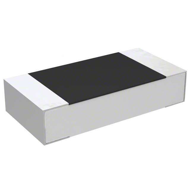
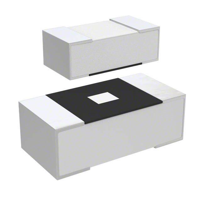
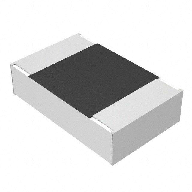
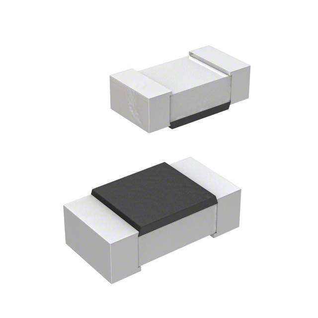
| 产品图片 |
|
| 产品型号 | PF0603FRE7T0R01Z |
| rohs | 无铅 / 符合限制有害物质指令(RoHS)规范要求 |
| 产品系列 | PF |
| 供应商器件封装 | 0603 |
| 其它名称 | 0.01NRTR |
| 功率(W) | 0.3W |
| 包装 | 带卷 (TR) |
| 大小/尺寸 | 0.063" 长 x 0.031" 宽(1.60mm x 0.80mm) |
| 容差 | ±1% |
| 封装/外壳 | 0603(1608 公制) |
| 工作温度 | -55°C ~ 155°C |
| 成分 | 厚膜 |
| 标准包装 | 5,000 |
| 温度系数 | ±50ppm/°C |
| 特性 | 电流感应, 防潮 |
| 电阻(Ω) | 0.01 |
| 端子数 | 2 |
| 高度 | 0.030"(0.75mm) |


- 商务部:美国ITC正式对集成电路等产品启动337调查
- 曝三星4nm工艺存在良率问题 高通将骁龙8 Gen1或转产台积电
- 太阳诱电将投资9.5亿元在常州建新厂生产MLCC 预计2023年完工
- 英特尔发布欧洲新工厂建设计划 深化IDM 2.0 战略
- 台积电先进制程称霸业界 有大客户加持明年业绩稳了
- 达到5530亿美元!SIA预计今年全球半导体销售额将创下新高
- 英特尔拟将自动驾驶子公司Mobileye上市 估值或超500亿美元
- 三星加码芯片和SET,合并消费电子和移动部门,撤换高东真等 CEO
- 三星电子宣布重大人事变动 还合并消费电子和移动部门
- 海关总署:前11个月进口集成电路产品价值2.52万亿元 增长14.8%


PDF Datasheet 数据手册内容提取
CURRENT SENSOR-LOW TCR PF0603-series 5%,1%, size 0603 RoHS Compliant & Halogen Free 0 V 0 1 0 2 , 7 1 . b e F – n o i t a c i f i c e p s ct u d www.yageo.com o r P
1 Chip Resistor Surface Mount PF SERIES 0603 6 SCOPE ORDERING INFORMATION - GLOBAL PART NUMBER Part number is identified by the series name, s ize, This specification describes PF0603 current tolerance, packaging type, temperature coefficient of sensor – low TCR chip resistors with resistance, taping reel, resistance value. lead-free terminations. X X X XX XXXX Z APPLICATIONS PF0603 (1) (2) (3) (4) (5) (6) ● Power supplies (1) TOLERANCE ● Consumer(Mobile、PNDs、…) F = ±1% ● Laptop ● HDDs J = ±5% FEATURES (2) PACKAGING TYPE ● Products with lead free terminations meet R = Paper/PE taping reel RoHS requirements. ● High component and equipment reliability (3)TEMPERATURE COEFFICIENT OF RESISTANCE with high power rating 0.33W (1/3W). E=±50ppm/°C, M=±75ppm/°C, F=±100ppm/°C ● Low resistance 10mΩ and narrow tolerance ±1% can suitable for current (4) TAPING REEL detection. 07 = 7 inch dia. Reel & 0.1W(1/10W) 7W = 7 inch dia. Reel & Power Rating 0.2W(1/5W) 7T = 7 inch dia. Reel & Power Rating 0.33W(1/3W) 47 = 7 inch dia. Reel & Power Rating 0.4W 57 = 7 inch dia. Reel & Power Rating 0.5W (5) RESISTANCE VALUE 0R01 (10mR) to 0R1 (100mR) (6) Default Code Letter Z is system default code for order only(NOTE) ORDERING EXAMPLE The ordering code for a PF0603 0.2W chip resistor,TC100 value 0.068Ω(68mR) with ±1% tolerance, supplied in 7-inch tape reel with 5Kpcs quantify is: PF0603FRF7W0R068Z. NOTE 1. All our RSMD products meet RoHS compliant and Halogen Free. "LFP" of the internal 2D reel label mentions "Lead Free Process". 2. On customized label, "LFP" or specific symbol can be printed. www.yageo.com
2 Chip Resistor Surface Mount PF SERIES 0603 6 MARKING PF0603: Fig.1 Value=10m Ω CONSTRUCTION OUTLINES The resistors are constructed out of For dimension see Table 1 a high-grade ceramic body. Internal metal electrodes are added at each end and connected by a resistive paste. The composition of the paste is adjusted to give the approximate required resistance and laser cutting of this resistive layer that achieves tolerance trims the value. The resistive layer is covered with a protective coat and printed with the resistance value. Finally, the two external terminations (matte tin) are added. See fig. 2. Fig.2 Chip resistor outlines DIMENSIONS Table 1 TYPE PF0603 L (mm) 1.60±0.20 W (mm) 0.80±0.20 H (mm) 0.60±0.15 I1 (mm) 0.30±0.15 www.yageo.com
3 Chip Resistor Surface Mount PF SERIES 0603 6 ELECTRICAL CHARACTERISTICS Table 2 CHARACTERISTICS PF0603 0.1W;0.2W;0.33W;0.4W;0.5W Operating Temperature Range –55°C to +155°C Maximum Working Voltage (P *R) Resistance Range 10mΩ to 100m Ω Temperature Coefficient ± 50ppm/℃,± 75ppm/℃, ±100ppm/°C PACKING STYLE AND PACKAGING QUANTITY Table 3 PRODUCT TYPE PACKING STYLE REEL DIMENSION QUANTITY PER REEL PF0603 Paper taping reel 7" (178 mm) 5,000 Units FUNCTIONAL DESCRIPTION POWER RATING PF0603 rated power at 70°C is 0.1W; 0.2W ; 0.33W; 0.4W and 0.5W RATED VOLTAGE The DC or AC (rms) continuous working voltage corresponding to the rated power is determined by the following formula: U= (P *R) Where U=Continuous rated DC or AC (rms) working voltage (v) P=Rated power R=Resistance value (Ω) www.yageo.com
4 Chip Resistor Surface Mount PF SERIES 0603 6 TAPING REEL Table 4 DIMENSION 0603 Tape Width(mm) 8 ØA (mm) 180.0+0/-3 ØN (mm) 60.0+1/-0 ØC (mm) 13.0±0.2 ØD (mm) 21.0±0.8 W1 (mm) 8.4 +1/-0 W2 (mm) Max 18.4 Fig.4 Reel PAPER/PE TAPE SPECIFICATION Table 5 DIMENSION 0603 A (mm) 1.10±0.15 0 B (mm) 1.90±0.15 0 W (mm) 8.0±0.30 E (mm) 1.75±0.10 F (mm) 3.50±0.10 P (mm) 4.0±0.10 0 P (mm) 4.0±0.10 1 P (mm) 2.0±0.10 2 D (mm) 1.50±0.10 0 T (mm) 0.85±0.15 Fig.5 Paper/PE tape www.yageo.com
5 Chip Resistor Surface Mount PF SERIES 0603 6 FOOTPRINT DIMENSION Size Footprint Dimensions Code unit :mm PF0603 A B C D 2.10 0.60 0.75 0.92 Fig.6 RECOMMENDED FOOTPRINT DIMENSIONS www.yageo.com
6 Chip Resistor Surface Mount PF SERIES 0603 6 TESTS AND REQUIREMENTS TEST TEST METHOD PROCEDURE REQUIREMENT Life/ IEC 60115-1 4.25.1 1,000 hours at 70±5 °C applied RCWV ± (1.0 % + 0.0005Ω) Endurance 1.5 hours on, 0.5 hour off, still air required High IEC 60068-2-2 1,000 hours at 155±5 °C,unpowered ± (1.0 % + 0.0005Ω) Temperature Exposure/ Endurance at upper category temperature Moisture MIL-STD-202 Method 106G Each temperature / humidity cycle is defined at ± ( 0.5% + 0.0005Ω) Resistance 8 hours (Method 106G), 3 cycles / 24 hours for 10d. with 25 °C / 65 °C 95% R.H, without steps 7a & 7b, un-powered Parts mounted on test-boards, without condensation on parts Measurement at 24±2 hours after test conclusion. Thermal MIL-STD-202 Method 107G -55/+125 °C ± ( 1.0% + 0.0005Ω) Shock Note: Number of cycles required is 300. Devices unmounted Maximum transfer time is 20 seconds. Dwell time is 15 minutes. Air – Air Short time IEC 60115-1 4.13 Applied 5 times of rating power 5 seconds at ± (0.5% + 0.0005Ω) overload room temperature No visible damage Board Flex/ IEC 60068-2-21 Chips mounted on a 90mm glass epoxy resin ± (1.0 % + 0.0005Ω) Bending PCB(FR4) 2 mm bending Bending time: 60±1 seconds Solderability IPC/JEDEC J-STD-002B Electrical Test not required Well tinned (>95% - Wetting test B Magnification 50X covered) SMD conditions: No visible damage 1st step: Method B, aging 4 hours at 155° C dry heat 2nd step: leadfree solder bath at 245±3 °C Dipping time: 3±0.5 seconds - Leaching IPC/JEDEC J-STD-002B Leadfree solder, 260 °C, 30 seconds No visible damage test D immersion time - Resistance IEC 60068-2-58 Condition B, no pre-heat of samples ± ( 0.5% + 0.0005Ω) to Soldering Leadfree solder, 260±5 °C, 10±1seconds No visible damage Heat immersion time Procedure 2 for SMD: devices fluxed and cleaned with isopropanol www.yageo.com
7 Chip Resistor Surface Mount PF SERIES 0603 6 REVISION HISTORY REVISION DATE CHANGE NOTIFICATION DESCRIPTION Version 0 2010-02-17 - First issue of this specification Version 1 2010-12-16 - Range Extension Version 2 2011-6-15 - Dimension of Paper Tape Modify Version 3 2011-12-2 - Dimension of Paper Tape Modify www.yageo.com