ICGOO在线商城 > 继电器 > 信号继电器,高达 2 A > HY1-5V
 Datasheet下载
- 型号: HY1-5V
- 制造商: Panasonic Corporation
- 库位|库存: xxxx|xxxx
- 要求:
| 数量阶梯 | 香港交货 | 国内含税 |
| +xxxx | $xxxx | ¥xxxx |
查看当月历史价格
查看今年历史价格
HY1-5V产品简介:
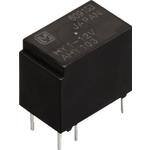
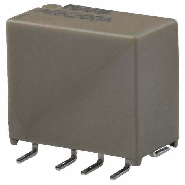
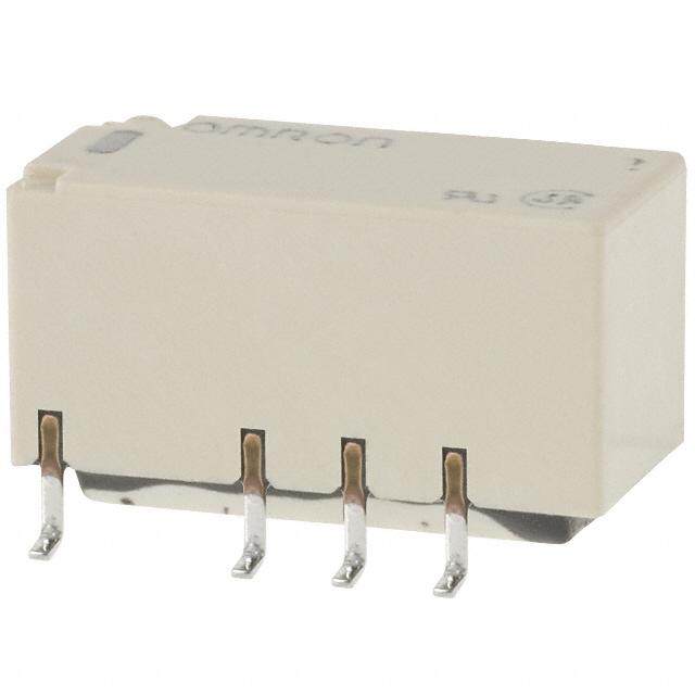
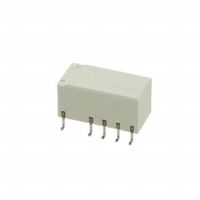
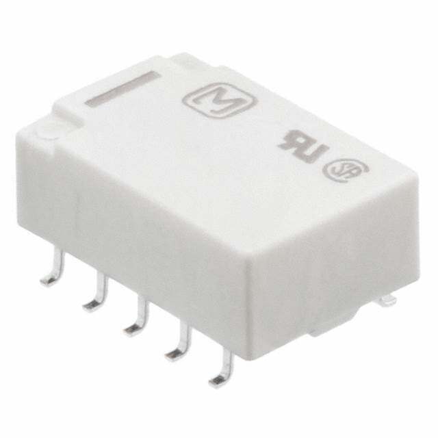
ICGOO电子元器件商城为您提供HY1-5V由Panasonic Corporation设计生产,在icgoo商城现货销售,并且可以通过原厂、代理商等渠道进行代购。 HY1-5V价格参考。Panasonic CorporationHY1-5V封装/规格:信号继电器,高达 2 A, 电信 继电器 SPDT(1 Form C) 通孔。您可以下载HY1-5V参考资料、Datasheet数据手册功能说明书,资料中有HY1-5V 详细功能的应用电路图电压和使用方法及教程。
Panasonic Electric Works(现为 Panasonic Industrial Devices)生产的 HY1-5V 型号信号继电器,额定负载高达 2A,适用于多种工业和家用场景。以下是其主要应用场景的详细说明:

 1. 工业自动化控制
   - 设备保护与切换:HY1-5V 可用于工业设备中的信号切换和保护电路,例如温度、压力或液位传感器的信号传递。
   - PLC 系统:在可编程逻辑控制器(PLC)中,该继电器可用于实现输入/输出信号的隔离与转换,确保系统的稳定性和安全性。
   - 电机控制:用于小型电机的启动/停止控制,尤其是在需要低电压驱动高电压负载的情况下。

 2. 家用电器
   - 智能家电:如空调、冰箱、洗衣机等设备中,该继电器可用于控制风扇、压缩机或其他小功率部件的运行状态。
   - 照明系统:在智能家居照明中,HY1-5V 可用于根据传感器信号(如光敏或人体感应)控制灯具的开关。

 3. 汽车电子
   - 辅助控制系统:适用于汽车内的信号传输和控制,例如车窗升降、雨刷器控制或报警系统。
   - 新能源汽车:在电动汽车或混合动力汽车中,用于低压电路的信号切换和保护。

 4. 通信与安防
   - 监控设备:用于摄像头、门禁系统等安防设备中的信号传递和电源控制。
   - 网络设备:在路由器、交换机等通信设备中,作为信号隔离和切换组件使用。

 5. 医疗设备
   - 仪器控制:在一些小型医疗设备中(如监护仪、理疗仪),该继电器可用于信号切换和设备保护。

 6. 其他应用
   - 太阳能系统:用于小型光伏系统的信号控制和电池管理。
   - 实验设备:在实验室环境中,用于测试仪器的信号切换和电路保护。

 特点总结
HY1-5V 继电器具有以下优点:
- 低功耗驱动:工作电压为 5V,适合现代低电压系统。
- 高可靠性: Panasonic 品牌保证了产品的耐用性和稳定性。
- 小型化设计:便于集成到紧凑型设备中。

综上所述,HY1-5V 信号继电器广泛应用于工业、家用、汽车、通信和医疗等多个领域,能够满足不同场景下的信号切换和控制需求。
| 参数 | 数值 |
| 产品目录 | |
| 描述 | RELAY TELECOM SPDT 1A 5V低信号继电器 - PCB 1A 5VDC SPDT 150mW PCB |
| 产品分类 | |
| 品牌 | Panasonic Electric Works |
| 产品手册 | http://www3.panasonic.biz/ac/e_download/control/relay/signal/catalog/mech_eng_hy.pdf?f_cd=302262 |
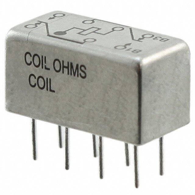
| 产品图片 |
|
| rohs | RoHS 合规性豁免无铅 / 符合限制有害物质指令(RoHS)规范要求 |
| 产品系列 | 低信号继电器 - PCB,Panasonic Industrial Devices HY1-5VHY |
| 数据手册 | |
| 产品型号 | HY1-5V |
| 产品 | Automotive Relays |
| 产品培训模块 | http://www.digikey.cn/PTM/IndividualPTM.page?site=cn&lang=zhs&ptm=17685 |
| 产品目录绘图 |
|
| 产品目录页面 | |
| 产品种类 | 低信号继电器 - PCB |
| 关闭电压(最小值) | 0.5 VDC |
| 其它名称 | 255-1092 |
| 其它有关文件 | |
| 功耗 | 150 mW |
| 包装 | 管件 |
| 商标 | Panasonic Industrial Devices |
| 安装类型 | 通孔 |
| 安装风格 | Through Hole |
| 导通电压(最大值) | 3.75 VDC |
| 封装 | Tube |
| 工作时间 | 5ms |
| 工作温度 | -40°C ~ 70°C |
| 工厂包装数量 | 50 |
| 开关电压 | 60VDC - 最小值 |
| 最大开关电流 | 1 A |
| 标准包装 | 50 |
| 特性 | 密封式 - 全部 |
| 端子类型 | PC 引脚 |
| 端接类型 | Solder Pin |
| 类型 | Miniature |
| 线圈功率 | 150 mW |
| 线圈电压 | 5VDC |
| 线圈电流 | 30mA |
| 线圈电阻 | 166 欧姆 |
| 线圈类型 | 无锁存 |
| 继电器类型 | 电信 |
| 触头外形 | SPDT(1 C 型) |
| 触头材料 | Silver(Ag),Gold(Au) |
| 触点形式 | SPDT (1 Form C) |
| 触点电流额定值 | 2 A |
| 触点额定值 | 1 A at 30 VDC |
| 释放时间 | 4ms |
| 额定接触(电流) | 1A |


- 商务部:美国ITC正式对集成电路等产品启动337调查
- 曝三星4nm工艺存在良率问题 高通将骁龙8 Gen1或转产台积电
- 太阳诱电将投资9.5亿元在常州建新厂生产MLCC 预计2023年完工
- 英特尔发布欧洲新工厂建设计划 深化IDM 2.0 战略
- 台积电先进制程称霸业界 有大客户加持明年业绩稳了
- 达到5530亿美元!SIA预计今年全球半导体销售额将创下新高
- 英特尔拟将自动驾驶子公司Mobileye上市 估值或超500亿美元
- 三星加码芯片和SET,合并消费电子和移动部门,撤换高东真等 CEO
- 三星电子宣布重大人事变动 还合并消费电子和移动部门
- 海关总署:前11个月进口集成电路产品价值2.52万亿元 增长14.8%


PDF Datasheet 数据手册内容提取
Non-polarized 1 Form C HY RELAYS relay that realizes nominal operating power of 150 mW FEATURES TYPICAL APPLICATIONS 1.Nominal operating power: 1.Telecommunications equipment High sensitivity of 150mW (Single 2.Security equipment side stable type) 3.Test and Measurement equipment A nominal operating power of 150 mW 4.Consumer electronic and Audio (minimum operating power of 84 mW) visual equipment has been achieved. 2.The use of gold-clad twin contacts ensures high contact reliability. 3.Sealed construction RoHS compliant ORDERING INFORMATION HY 1 Contact arrangement 1: 1 Form C Sensitivity Nil:High sensitivity 150 mW Z: Standard 200 mW Nominal coil voltage (DC) 1.5, 3, 4.5, 5, 6, 9, 12, 24 V Note:In case of 5 V drive circuit, it is recommended to use 4.5 V type relay. TYPES Contact Nominal coil 150mW type 200mW type arrangement voltage Part No. Part No. 1.5V DC HY1-1.5V HY1Z-1.5V 3V DC HY1-3V HY1Z-3V 4.5V DC HY1-4.5V HY1Z-4.5V 5V DC HY1-5V HY1Z-5V 1 Form C 6V DC HY1-6V HY1Z-6V 9V DC HY1-9V HY1Z-9V 12V DC HY1-12V HY1Z-12V 24V DC HY1-24V HY1Z-24V Standard packing: Tube: 50 pcs.; Case: 2,000 pcs. –1– ASCTB212E 201503-T
HY RATING 1. Coil data Nominal operating Max. applied Contact Nominal coil Pick-up voltage Drop-out voltage Coil resistance Nominal operating arrangement voltage (at 20°C 68°F) (at 20°C 68°F) [±10%] c(autr r2e0n°tC 68°F) [±10%] (at 20°C 68°F) power (at 7v0o°lCta 1g5e8 °F) 1.5V DC 100mA 15Ω 3V DC 50mA 60Ω 4.5V DC 33.3mA 135Ω 5V DC 75%V or less of 10%V or more of 30mA 166Ω 140%V of nominal voltage nominal voltage 150mW 6V DC (Initial) (Initial) 25mA 240Ω nominal voltage 9V DC 16.7mA 540Ω 12V DC 12.5mA 960Ω 24V DC 6.25mA 3,840Ω 1 Form C 1.5V DC 133.3mA 11.25Ω 3V DC 66.7mA 45Ω 4.5V DC 44.5mA 101.2Ω 5V DC 75%V or less of 10%V or more of 40mA 125Ω 120%V of nominal voltage nominal voltage 200mW 6V DC (Initial) (Initial) 33.3mA 180Ω nominal voltage 9V DC 22.2mA 405Ω 12V DC 16.7mA 720Ω 24V DC 8.3mA 2,880Ω 2. Specifications Characteristics Item Specifications Arrangement 1 Form C Contact Initial contact resistance, max. Max. 100 mΩ (By voltage drop 6 V DC 1A) Contact material Ag+Au clad Nominal switching capacity 1 A 30 V DC (resistive load) Max. switching power 30 W (DC) (resistive load) Max. switching voltage 60 V DC Rating Max. carrying current 2 A Max. switching current 1 A (30 V DC) Min. switching capacity (Reference value)*1 1mA 1 V DC Nominal operating power 150/200mW Min. 100MΩ (at 500V DC) Insulation resistance (Initial) Measurement at same location as “Initial breakdown voltage” section. Breakdown voltage Between open contacts 500 Vrms for 1min. (Detection current: 10mA) (Initial) Between contact and coil 1,000 Vrms for 1min. (Detection current: 10mA) Electrical characteristics Temperature rise (at 20°C 68°F) Max. 50°C (By resistive method, nominal coil voltage applied to the coil, nominal switching capacity.) Operate time [Set time] (at 20°C 68°F) Max. 5 ms (Nominal coil voltage applied to the coil, excluding contact bounce time.) Release time [Reset time] (at 20°C 68°F) Max. 4 ms (Nominal coil voltage applied to the coil, excluding contact bounce time.) (without diode) Functional Min. 98 m/s2 (Half-wave pulse of sine wave: 11 ms; detection time: 10μs.) Shock resistance Mechanical Destructive Min. 980 m/s2 (Half-wave pulse of sine wave: 6 ms.) characteristics Functional 10 to 55 Hz at double amplitude of 1 mm (Detection time: 10μs.) Vibration resistance Destructive 10 to 55 Hz at double amplitude of 2 mm Mechanical Min. 107 (at 180 cpm) Expected life Electrical Min. 105 (1 A 30 V DC resistive) (at 20 cpm) Ambient temperature: –40°C to +70°C –40°F to +158°F Conditions for operation, transport and storage*2 Conditions Humidity: 5 to 85% R.H. (Not freezing and condensing at low temperature) Max. operating speed (at rated load) 20 cpm Unit weight Approx. 1.8 g .063 oz Notes:*1 This value can change due to the switching frequency, environmental conditions, and desired reliability level, therefore it is recommended to check this with the actual load. *2 Refer to 6. Conditions for operation, transport and storage mentioned in AMBIENT ENVIRONMENT. –2– ASCTB212E 201503-T
HY REFERENCE DATA 1. Maximum switching power 2. Life curve 3. Mechanical life Tested sample: HY1Z-12V, 10 pcs. Ambient temperature: 20°C to 25°C 68°F to 77°F 5.0 100 300 V Contact current, A012...500 DACC rreessiissttiivvee ×4Life, 1012123500000000 3re0s iVs tDivCe load ainst the rated voltage, % 456789000000 Pick-up voltage MMianx.. 0.2 1re0s0is Vtiv AeC lo ad atio ag 2300 Drop-out voltage Max. R Min. 10 0.1 0 10 30 60 100 300 0.2 0.4 0.6 0.8 1.0 1.2 1.4 10 100 1,0002,000 Contact voltage, V Switching current, A No. of operations, ×104 4. Electrical life Change of pick-up and drop-out voltage Change of contact resistance Tested sample: HY1-12V, 6 pcs. 100 Condition: 1 A 30 V DC resistive load, 30 cpm V % o against the rated voltage, 34567890000000 DPriocpk--uopu tv vooltlataggee MMMaianxx... ΩContact resistance, m 864000 MMianx.. Rati 20 Min. 20 10 0 0 10 20 10 20 No. of operations, ×104 No. of operations, × 104 5-(1). Coil temperature rise 5-(2). Coil temperature rise 6. Operate/release time characteristics (150 mW high sensitivity type) (200 mW Standard type) Tested sample: HY1Z-12V, 5 pcs. Tested sample: HY1-9V, 5 pcs. Tested sample: HY1Z-12V, 5 pcs. Ambient temperature: 25°C 77°F Ambient temperature:24°C 75°F Ambient temperature: 23°C 74°F 100 100 3 90 90 °Coil temperature rise, C 345678000000 1A 0A °Coil temperature rise, C 345678000000 1A 0A Operate/release time, ms 21 ORpeeleraastee ttiimmee MMMxaianxx... x 20 20 Min. 10 10 0 0 0 80 100 120 140 160 180 80 100 120 140 160 180 80 100 120 Coil applied voltage, %V Coil applied voltage, %V Coil applied voltage, %V 7. Distribution of pick-up and drop-out voltages 8. Distribution of contact resistance 9. Malfunction shock Tested sample: HY1-12V, 50 pcs. Tested sample: HY1-12V, 50 pcs. Tested sample: HY1Z-12V, 6 pcs. Ambient temperature: 23°C 74°F N.C. side N.O. side 30 30 NN..CO.. ssiiddee Z’ZXX’ 980m/s2Y DEneeerngeizrgeidz ecdo ncdointidointion 25 Drop-out voltage 25 Y Y’ 980m/s2 X Z uantity 1250 Pick-up voltage uantity 1250 980m/s2 Q Q 10 10 980m/s2 980m/s2 Z’ X’ 5 5 980m/s2 Y’ 0 0 10 20 30 40 50 60 70 80 90100 30 40 Pick-up/drop-out voltage, V Contact resistance mΩ –3– ASCTB212E 201503-T
HY DIMENSIONS (mm inch) The CAD data of the products with a CAD Data mark can be downloaded from: http://industrial.panasonic.com/ac/e/ CAD Data External dimensions PC board pattern (Bottom view) .72.941 .41622 2.1.5040 7.3.6020 66--.10 3d9ia .dia. 10.1 5.08 .398 .200 2.54 3.5 .100 .138 0.5 0.5 .020 (0.82) .020 0.4 dia. (.032) 5.08 .016 dia. .200 0.0.2150 0.0.2150 Tolerance: ±0.1 ±.004 2.1.5040 7.3.6020 ((0.0.8322)) Schematic (Bottom view) General tolerance: ±0.3 ±.012 1 2 5 NC COM NO 10 9 6 NOTE 1. Packing style 2. Automatic insertion 1) As shown in the diagram below, the To maintain the internal function of the relays are presented in tube packages relay, the chucking pressure should not with pins 1 and 10 on the left. Be sure to exceed the values below. maintain relays in the correct orientation Chucking pressure in the direction A: when mounting on PC boards. 4.9 N {500gf} or less Chucking pressure in the direction B: Side with pins 1 and 10. 4.9 N {500gf} or less Chucking pressure in the direction C: 4.9 N {500gf} or less C A B Stopper Stopper (gray) (green) Avoid chucking the center of the relay. In addition, excessive chucking pressure to the pinpoint of the relay should be avoided. For general cautions for use, please refer to the “Cautions for use of Signal Relays” or “General Application Guidelines”. –4– ASCTB212E 201503-T
Mouser Electronics Authorized Distributor Click to View Pricing, Inventory, Delivery & Lifecycle Information: P anasonic: HY1-1.5V HY1-4.5V HY1-6V HY1-9V HY1Z-1.5V HY1Z-3V HY1Z-4.5V HY1Z-6V HY1Z-9V HY1-5V HY1Z-5V HY1-12V HY1Z-12V HY1-3V HY1Z-24V HY1-24V