ICGOO在线商城 > 继电器 > 信号继电器,高达 2 A > G6AK-274P-ST-US-DC12
 Datasheet下载
- 型号: G6AK-274P-ST-US-DC12
- 制造商: Omron Electronics LLC
- 库位|库存: xxxx|xxxx
- 要求:
| 数量阶梯 | 香港交货 | 国内含税 |
| +xxxx | $xxxx | ¥xxxx |
查看当月历史价格
查看今年历史价格
G6AK-274P-ST-US-DC12产品简介:
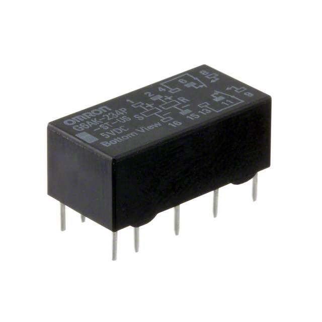
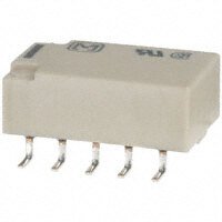
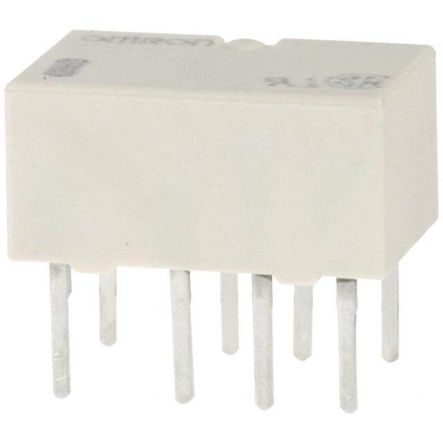
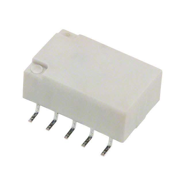
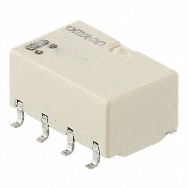
ICGOO电子元器件商城为您提供G6AK-274P-ST-US-DC12由Omron Electronics LLC设计生产,在icgoo商城现货销售,并且可以通过原厂、代理商等渠道进行代购。 G6AK-274P-ST-US-DC12价格参考。Omron Electronics LLCG6AK-274P-ST-US-DC12封装/规格:信号继电器,高达 2 A, 通用 继电器 DPDT(2 Form C) 通孔。您可以下载G6AK-274P-ST-US-DC12参考资料、Datasheet数据手册功能说明书,资料中有G6AK-274P-ST-US-DC12 详细功能的应用电路图电压和使用方法及教程。
欧姆龙电子有限公司(OMRON Electronics Inc.)EMC部门生产的型号为G6AK-274P-ST-US-DC12的信号继电器,是一种高性能、小体积的电磁继电器,额定电流高达2A,适用于多种工业与自动化控制场景。

该继电器的主要应用场景包括:

1. 工业自动化控制系统:用于PLC(可编程逻辑控制器)、开关柜、传感器信号切换等场合,实现对设备的自动控制。
2. 测试与测量设备:在各类电子测试仪器中用作信号通断控制元件,确保测试过程的稳定性与准确性。
3. 通信设备:用于电信交换系统或数据通信设备中,进行电路切换或隔离。
4. 医疗设备:在需要高可靠性和安全性的医疗仪器中,作为关键控制元件使用。
5. 安防系统:如报警系统、门禁控制系统中,用于触发和控制外围设备。
6. 能源管理系统:在智能电表、能源监控系统中,用于负载控制和电路隔离。

该继电器具备良好的抗干扰能力(EMC性能优异),并采用标准封装形式,便于PCB安装,适合在紧凑型电子设备中应用。其线圈电压为直流12V(DC12),具有较高的操作稳定性和长寿命特性。
| 参数 | 数值 |
| 产品目录 | |
| 描述 | RELAY GEN PURPOSE DPDT 2A 12V低信号继电器 - PCB STD DPDT 12VDC Latching |
| 产品分类 | |
| 品牌 | Omron Electronics |
| 产品手册 | |
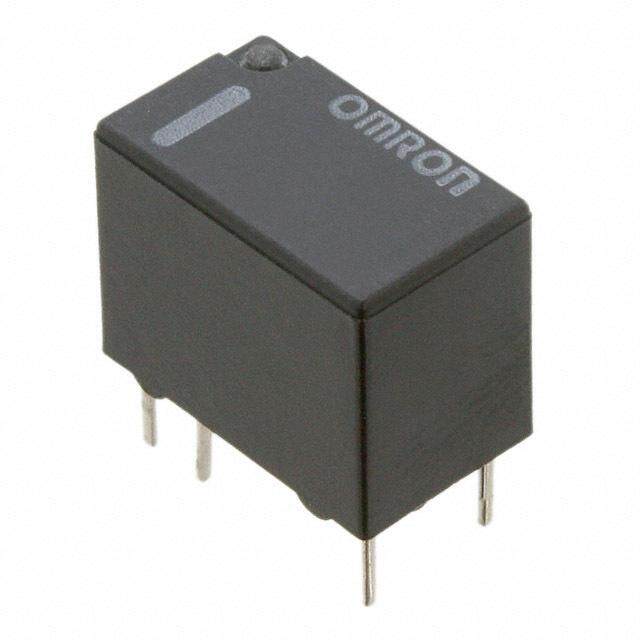
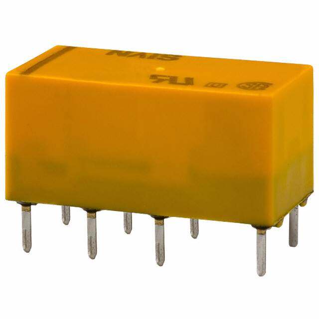
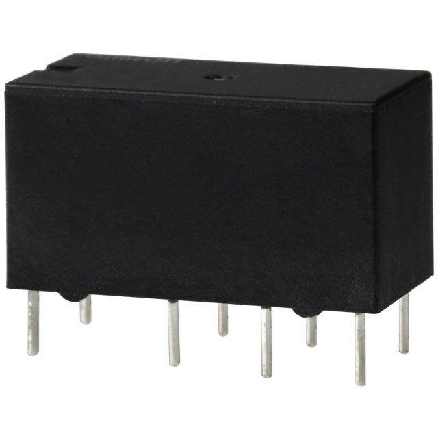
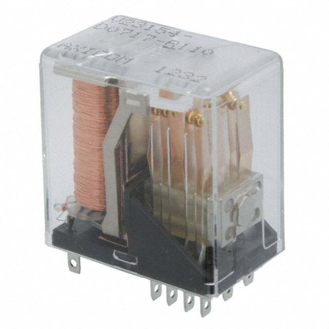
| 产品图片 |
|
| rohs | 符合RoHS无铅 / 符合限制有害物质指令(RoHS)规范要求 |
| 产品系列 | 低信号继电器 - PCB,Omron Electronics G6AK-274P-ST-US-DC12G6A |
| mouser_ship_limit | 该产品可能需要其他文件才能进口到中国。 |
| 数据手册 | |
| 产品型号 | G6AK-274P-ST-US-DC12 |
| 产品 | Low Profile Relays |
| 产品培训模块 | http://www.digikey.cn/PTM/IndividualPTM.page?site=cn&lang=zhs&ptm=25458 |
| 产品目录绘图 |
|
| 产品目录页面 | |
| 产品种类 | 低信号继电器 - PCB |
| 关闭电压(最小值) | - |
| 其它名称 | G5LN8035B |
| 其它有关文件 | |
| 功耗 | 180 mW |
| 包装 | 管件 |
| 商标 | Omron Electronics |
| 安装类型 | 通孔 |
| 安装风格 | Through Hole |
| 导通电压(最大值) | 8.4 VDC |
| 工作时间 | 5ms |
| 工作温度 | -40°C ~ 70°C |
| 工厂包装数量 | 25 |
| 开关电压 | 250VAC,220VDC - 最小值 |
| 最大开关电流 | 2 A |
| 标准包装 | 25 |
| 特性 | - |
| 端子类型 | PC 引脚 |
| 端接类型 | Solder Pin |
| 类型 | Miniature |
| 系列 | G6A |
| 线圈功率 | 180 mW |
| 线圈电压 | 12 V |
| 线圈电流 | 15 mA |
| 线圈电阻 | 800 欧姆 |
| 线圈类型 | Dual Coil Latching |
| 继电器类型 | 通用 |
| 触头外形 | DPDT(2 C 型) |
| 触头材料 | Silver(Ag),Gold(Au) |
| 触点形式 | DPDT (2 Form C) |
| 触点额定值 | 0.50 A at 125 VAC, 2 A at 30 VDC |
| 释放时间 | 5ms |
| 零件号别名 | 374831 G6AK1119F G6AK274PSTUS12DC G6AK274PSTUS12DCG6AK274PSTUSDC12NC G6AK274PSTUSDC12NC |
| 额定接触(电流) | 2A |


- 商务部:美国ITC正式对集成电路等产品启动337调查
- 曝三星4nm工艺存在良率问题 高通将骁龙8 Gen1或转产台积电
- 太阳诱电将投资9.5亿元在常州建新厂生产MLCC 预计2023年完工
- 英特尔发布欧洲新工厂建设计划 深化IDM 2.0 战略
- 台积电先进制程称霸业界 有大客户加持明年业绩稳了
- 达到5530亿美元!SIA预计今年全球半导体销售额将创下新高
- 英特尔拟将自动驾驶子公司Mobileye上市 估值或超500亿美元
- 三星加码芯片和SET,合并消费电子和移动部门,撤换高东真等 CEO
- 三星电子宣布重大人事变动 还合并消费电子和移动部门
- 海关总署:前11个月进口集成电路产品价值2.52万亿元 增长14.8%
PDF Datasheet 数据手册内容提取
G6A Low Signal Relay World's Standard Model G6A! •Resistant to electromagnetic interference, enables high-density mounting. •Impulse withstand voltage of 1,500V meets FCC requirements. •Gold-clad twin-contacts provide short contact bounce in addition to its high contact reliability. •A variety of products that cover a wide range of use. RoHS Compliant ■Model Number Legend ■Application Examples •Telecommunication equipment G6A@-@@@@-@-@ 5. Terminal Shape •Security equipment G 1 2 3 4 5 6 7 P: PCB Terminals 6 6. Classification •Test & measurement equipment A 1. Relay Function None : Standard None : Single-side stable ST : Stand-off 0.64 mm U : Single-winding latching 15 : High-sensitivity (150 mW) K : Double-winding latching 40 : Low-sensitivity (Single-side Stable: 400 mW 2. Contact Form Double-winding Latching: 360 mW) 2: DPDT (2c) 7. Approved Standards 3. Contact Type 7: Bifurcated crossbar Ag (Au-Alloy) None : Standard US : UL/C-UL 4. Protective Structure 4: Fully sealed ■Ordering Information ●UL/C-UL Certified Models Relay Function Classification Contact form Model Rated coil voltage (VDC) Minimum packing unit 3, 4.5, 5, 6, 9, 12, 24 Standard G6A-274P-ST-US 48 Single-side Stable 3, 5, 6, 9, 12, 24 Low-sensitivity G6A-274P-ST40-US Type 48 3, 5, 6, 9, 12, 24 High-sensitivity G6A-274P-ST15-US 48 DPDT (2c) 25 pcs/tube Single-winding 3, 4.5, 5, 6, 9, 12, 24 Standard G6AU-274P-ST-US Latching Type 48 3, 4.5, 5, 6, 9, 12, 24 Standard G6AK-274P-ST-US Double-winding 48 Latching Type 3, 5, 6, 9, 12, 24 Low-sensitivity G6AK-274P-ST40-US 48 Note:When ordering, add the rated coil voltage to the model number. Example: G6A-274P-ST-US DC3 Rated coil voltage However, the notation of the coil voltage on the product case as well as on the packing will be marked as @@ VDC. 1
G6A Low Signal Relay ■Ratings ●Coil: Single-side Stable (Standard Models) Must operate voltage Must release voltage Max. voltage Contact form Rated voltage Rate(dm cAu)rrent Coil re(sΩis)tance (V) (V) (V) Power c(monWsu)mption % of rated voltage 3 VDC 66.7 45 4.5 VDC 44.6 101 5 VDC 40.0 125 6 VDC 33.3 180 200% Approx. 200 DPDT (2c) 70% max. 10% min. 9 VDC 22.2 405 (at 23°C) 12 VDC 16.7 720 24 VDC 8.3 2,880 48 VDC 4.9 9,750 Approx. 235 Note1.The rated current and coil resistance are measured at a coil temperature of 23°C with a tolerance of ±10%. 2.Operating characteristics are measured at a coil temperature of 23°C. 3.The maximum voltage is the highest voltage that can be imposed on the relay coil. ●Coil: Single-side Stable (Low-sensitivity Models) Must operate voltage Must release voltage Max. voltage Contact form Rated voltage Rate(dm cAu)rrent Coil re(sΩis)tance (V) (V) (V) Power c(monWsu)mption % of rated voltage 3 VDC 133.3 22.5 5 VDC 80 62.5 G 6 6 VDC 66.7 90 A DPDT (2c) 9 VDC 44.3 203 70% max. 10% min. 150% Approx. 400 (at 23°C) 12 VDC 33.3 360 24 VDC 16.7 1,440 48 VDC 8.3 5,760 Note1.The rated current and coil resistance are measured at a coil temperature of 23°C with a tolerance of ±10%. 2.Operating characteristics are measured at a coil temperature of 23°C. 3.The maximum voltage is the highest voltage that can be imposed on the relay coil. ●Coil: Single-side Stable (High-sensitivity Models) Must operate voltage Must release voltage Max. voltage Contact form Rated voltage Rate(dm cAu)rrent Coil re(sΩis)tance (V) (V) (V) Power c(monWsu)mption % of rated voltage 3 VDC 50 60 4.5 VDC 33.3 135 5 VDC 30 167 6 VDC 25 240 200% DPDT (2c) 80% max. 10% min. Approx. 150 9 VDC 16.7 540 (at 23°C) 12 VDC 12.5 960 24 VDC 6.3 3,840 48 VDC 3.2 15,000 Note1.The rated current and coil resistance are measured at a coil temperature of 23°C with a tolerance of ±10%. 2.Operating characteristics are measured at a coil temperature of 23°C. 3.The maximum voltage is the highest voltage that can be imposed on the relay coil. ●Coil: Single-winding Latching Rated current Coil resistance Set voltage (V) Reset voltage (V) Max. voltage (V) Power consumption Contact form Rated voltage (mA) (Ω) % of rated voltage (mW) 3 VDC 33.7 89 5 VDC 20 250 6 VDC 16.7 360 200% Approx. 100 DPDT (2c) 9 VDC 11.1 810 70% max. 70% max. (at 23°C) 12 VDC 8.3 1,440 24 VDC 4.2 5,760 48 VDC 2.5 19,000 Approx. 120 Note1.The rated current and coil resistance are measured at a coil temperature of 23°C with a tolerance of ±10%. 2.Operating characteristics are measured at a coil temperature of 23°C. 3.The maximum voltage is the highest voltage that can be imposed on the relay coil. 2
G6A Low Signal Relay ●Coil: Double-winding Latching (Standard Models) Rated current Coil resistance Set voltage (V) Reset voltage (V) Max. voltage (V) Power consumption Contact form Rated voltage (mA) (Ω) % of rated voltage (mW) 3 VDC 66.7 45 Approx. 200 4.5 VDC 40.2 112 5 VDC 36 139 6 VDC 30 200 200% DPDT (2c) 70% max. 70% max. Approx. 180 9 VDC 20 450 (at 23°C) 12 VDC 15 800 24 VDC 7.5 3,200 48 VDC 4.2 11,520 Approx. 200 Note1.The rated current and coil resistance are measured at a coil temperature of 23°C with a tolerance of ±10%. 2.Operating characteristics are measured at a coil temperature of 23°C. 3.The maximum voltage is the highest voltage that can be imposed on the relay coil. ●Coil: Double-winding Latching (Low-sensitivity Models) Rated current Coil resistance Set voltage (V) Reset voltage (V) Max. voltage (V) Power consumption Contact form Rated voltage (mA) (Ω) % of rated voltage (mW) 3 VDC 120 25 4.5 VDC 79.9 56.3 5 VDC 72.5 69 6 VDC 60 100 150% DPDT (2c) 70% max. 70% max. Approx. 360 9 VDC 40 225 (at 23°C) G 6 12 VDC 30 400 A 24 VDC 15 1,600 48 VDC 7.5 6,400 Note1.The rated current and coil resistance are measured at a coil temperature of 23°C with a tolerance of ±10%. 2.Operating characteristics are measured at a coil temperature of 23°C. 3.The maximum voltage is the highest voltage that can be imposed on the relay coil. ●Contacts Load Inductive load Resistive load (cosφ = 0.4; ) Item L/R = 7 ms Contact type Bifurcated crossbar Contact material Ag (Au-Alloy) contact 0.5 A at 125 VAC; 0.3 A at 125 VAC; Rated load 2 A at 30 VDC 1 A at 30 VDC Rated carry current 3 A Max. switching voltage 250 VAC, 220 VDC Max. switching current 2 A 1 A 3
G6A Low Signal Relay ■Characteristics Item Classification Single-side Stable Single-winding Latching Double-winding Latching Contact resistance *1 50 mΩ max. Operate (set) time 5 ms max. 5 ms max. Release (reset) time 3 ms max. 5 ms max. Min. set/reset signal width − 10 ms Insulation resistance *2 1,000 MΩ min. (at 500 VDC); except for set-reset Between coil and contacts 1,000 VAC, 50/60 Hz for 1 min Between contacts of the 1,000 VAC, 50/60 Hz for 1 min same polarity Dielectric strength Between contacts of 1,000 VAC, 50/60 Hz for 1 min different polarity Between set and reset − − 250 VAC, 50/60 Hz for 1 min coils Impulse withstand voltage 1,500 V (10 × 160 μs) (conforms to FCC Part 68) Vibration Destruction 10 to 55 to 10 Hz, 2.5 mm single amplitude (5 mm double amplitude) resistance Malfunction 10 to 55 to 10 Hz, 1.65 mm single amplitude (3.3 mm double amplitude) Shock Destruction 1,000 m/s2 resistance Malfunction 500 m/s2 300 m/s2 Mechanical 100,000,000 operations min. (at 36,000 operations/hr) Durability Electrical 500,000 operations min. (at 1,800 operations/hr) G Failure rate (P level) *3 10 μA at 10 m VDC 6 Ambient operating temperature -40°C to 70°C (with no icing or no condenstion) A Ambient operating humidity 5% to 85% Weight Approx. 3.5 g Note:The data shown above are initial values. *1. The contact resistance was measured with 10 mA at 1 VDC with a voltage drop method. *2. The insulation resistance was measured with a 500 VDC megohmmeter applied to the same parts as those used for checking the dielectric strength (except between the set and reset coil). *3. This value was measured at a switching frequency of 60 operations/min and the criterion of contact resistance is 50 Ω. This value may vary, depending on switching frequency, operating conditions, expected reliability level of the relay, etc. It is always recommended to double-check relay suitability under actual load conditions. 4
G6A Low Signal Relay ■Engineering Data ●Maximum Switching Power ●Durability Switching current (A)521...000 D(LC/R i n=d 7u cmtivse) DC resistiveAC resistive bility (x104 operations) 10531,,,,000053000000000000 30 VDC, resistive a ur D 100 0.5 50 30 0.2 A(cCo sinφ d=u 0ct.i4v)e 105 125 VAC, resistive 30 VDC, inductive 3 125 VAC, inductive 0 20 50 100 200 500 0 0.2 0.4 0.6 0.8 1.0 1.2 1.4 1.6 1.8 2.0 Switching voltage (V) Switching current (A) ●Ambient Temperature vs. Maximum ●Ambient Temperature vs. Must Coil Voltage Operate or Must Release Voltage %)250 %)100 Maximum coil voltage (210500 100, 150, 200 mW basis of rated voltage ( 8600 SNaummpbleer: oGf 6RAe-l2a7y4sP: 10 pcs mmXainx.. GA6 e 110 n th max. 100 O 40 360, 400 mW X 50 20 min. Must operate voltage Must release voltage 0 0 -40 20 30 40 50 60 70 80 90 100 -60 -40 -20 0 20 40 60 80 100 120 Ambient temperature (°C) Ambient temperature (°C) Note:“Maximum voltage” is the maximum voltage that can be applied to the Relay coil. ●Shock Malfunction G6A-274P G6AK-274P Y Y 1,000 1,000 800 800 1,00X0 600 1,000Z 1,00X0 600 1,000Z 400 400 200 200 200 200 400 400 1,00Z0' 600 1,000X' 1,00Z0' 600 1,000X' 800 800 Shock direction De-energized Y X XZ' 1,000Y' UEnint:e mrg/isz2ed YShoXck direXctZ'ion 1,000Y' Unit: m/s2 Y' Z' Sample:G6A-274P 5 VDC Z' Sample:G6AK-274P 5 VDC Number of Relays: 10 pcs Y' Number of Relays: 10 pcs Test Conditions: Shock is applied in ±X, ±Y, and ±Z directions three times each with and without energizing the Relays to check the number of contact malfunctions. 5
G6A Low Signal Relay ●Electrical Durability Test *1 ●Contact Reliability Test *1, *2 basis of rated voltage (%) 876543000000 MMuusstt roepleearastee vvoollttaaggee mmmaianxx... Contact resistance (mW)1,053000000 S7SNT1,0ewau2 smmi0mttc0 pbcAh leooe in(rnp:R godeGe firft 6asriRoeiAtsienqo-tlsui2nav:e7sey Ln4/s hlocP:o ay1a :d0d5 ) 1pV0cD smC VDC NNOC ccoonnttaacctt On the 2100 SNaummpbleer: oGf 6RAe-l2a7y4sP: 10 pcs min. 100 Test conditions: 125 VAC 0.5 A (Resistive load) W)100 Switching frequency: 1,800 operations/h 50 max. Contact resistance (m 7530001NO con3tact 5NC c1o0ntact 30 50 100mmmmaaiinnxx.... 500 31000 3 5 10 30 50 100 300 1,00mmm0a iinnx3...,000 Operating frequency (×104 operations) Operating frequency (×104 operations) *1. The tests were conducted at an ambient temperature of 23ºC. *2. The contact resistance data are periodically measured reference values and are not values from each monitoring operation. Contact resistance values will vary according to the switching frequency and operating environment, so be sure to check operation under the actual operating conditions before use. ●Mutual Magnetic Interference G6A-274P G6A-274P Must operate voltage Must operate voltage Must release voltage Must release voltage G 2.54 mm %) +10Initial stage Test %)+10Initial stage Test A6 De-energizedSampleDe-energized Change rate on thebasis of initial value ( −1+−5050 Average vaXXlue 2.54 mm SaDe-menergizedple Change rate on thebasis of initial value (−1+−5050 Average vaXXlue Initial stage Test Initial stage Test EnergizedSampleEnergized Change rate on thebasis of initial value (%) +−11+−05050 Average vaXXlue SamEnergizedple Change rate on thebasis of initial value (%)+−11+−05050 Average vaXXlue ●External Magnetic Interference G6AK-274P (Average value) G6AK-274P (Average value) G6AK-274P (Average value) Rate of variability (%)++2100 N S SReets evot lvtaogltaege Rate of variability (%)++2100 SNaummpbleer: oGf 6RAeKla-2ys7:4 1P0 5 p VcsDC N S Rate of variability (%)++2100 SNaummpbleer: oGf 6RAeKla-2ys7:4 1P0 5 p VcsDC N S 0 0 0 −10 −10 −10 S N S N Set voltage S N Set voltage Sample: G6AK-274P 5 VDC Reset voltage Reset voltage −20 Number of Relays: 10 pcs −20 −20 −4,000 −2,400 −800 0 800 2,400 4,000 −4,000 −2,400 −800 0 800 2,400 4,000 −4,000 −2,400 −800 0 800 2,400 4,000 −3,200 −1,600 1,600 3,200 −3,200 −1,600 1,600 3,200 −3,200 −1,600 1,600 3,200 External magnetic field (A/m) External magnetic field (A/m) External magnetic field (A/m) 6
G6A Low Signal Relay ●Time distribution of Operating and Release/Set and Reset *1 G6A-274P G6AK-274P Number of contacts10800 SNaummpbleer: oGf 6RAe-l2a7y4sP: 5 50 VpDcsC MMuusstt orepleearastee ttiimmee Number of contacts 6400 SNaummpbleer: oGf 6RAeKlaSR-2yees7ts: 4 et5iPmt0 t5e imp VcesDC 60 40 20 20 0 0 1 2 3 4 1 2 3 4 Time (ms) Time (ms) ●Bounce Time distribution of Operating and Release/Set and Reset *1 G6A-274P G6AK-274P ntacts60 SNaummpbleer: oGf 6RAe-l2a7y4sP: 5 50 VpDcsC ntacts80 SNaummpbleer: oGf 6RAeKla-2ys7:4 5P0 5 p VcsDC o o mber of c ORepleeraastien gb obuonucnec eti mtimee mber of c60 SReets ebto buonucen cteim teime Nu40 Nu G 6 A 40 20 20 0 0.5 1.0 1.5 0 0.5 1.0 Time (ms) Time (ms) ●High-frequency Characteristics •Measurement Conditions G6A-274P HR 8505A RF HR 8501 Naneatwlyozrekr 850H1PA RA Trteersfalten-csstemiotinssion 50Ω Storage Terminator normalizer B Terminals which were not being measured were terminated with 50 Ω. Measuring impedance: 50 Ω Note:The high-frequency characteristics data were measured using a dedicated circuit board and actual values will vary depending on the usage conditions. Check the characteristics of the actual equipment being used. ●High-frequency Characteristics ●High-frequency Characteristics ●High-frequency Characteristics (Isolation) *1, *2 (Insertion Loss) *1, *2 (Return Loss, V.SWR) *1, *2 (Average value (initial)) (Average value (initial)) (Average value (initial)) Isolation (dB) 200 SNaummpbleer: oGf 6RAe-l2a7y4sP: 10 pcs Insertion loss (dB)0.05 Return loss (dB) 05 SNaummpbleer: oGf 6RAe-l2a7y4sP: 10 pRcesturn loss R W 40 10 S V. 60 15 2.0 1.0 80 20 1.5 Sample: G6A-274P V.SWR Number of Relays: 10 pcs 100 1.5 25 1.0 0 20 40 60 80 100 0 100 200 300 400 500 600 0 200 400 600 800 1,000 Frequency (MHz) Frequency (MHz) Frequency (MHz) *1. The tests were conducted at an ambient temperature of 23°C. *2. High-frequency characteristics depend on the PCB to which the Relay is mounted. Always check these characteristics, including durability, in the actual machine before use. 7
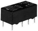
G6A Low Signal Relay ■Dimensions Single-side stable PCB Mounting Holes Terminal Arrangement/ G6A-274P-ST-US (BOTTOM VIEW) Internal Connections G6A-274P-ST40-US Tolerance: ±0.1 (BOTTOM VIEW) G6A-274P-ST15-US 10.1max. 2.54 Eight, 1.0-dia. holes 20(.220m)*ax. (9.9)* 2.54 (1.2) + 1 4 6 8 0.648.4max. 7.62 (8.2)* 16− 13 11 9 3.16 0.3 5.08 5.08 (1.2) Note:Check carefully the 0.6 7.62 (1.2) 7.62 (1.2) coil polarity of the * Average value Note: Orientation marks are indicated as follows: Relay. Note:Each value has a tolerance of ±0.3 mm. Single-winding latching PCB Mounting Holes Terminal Arrangement/ G6AU-274P-ST-US (BOTTOM VIEW) Internal Connections Tolerance: ±0.1 (BOTTOM VIEW) 2.54 Eight, 1.0-dia. holes 10.1max. 20.2max. (9.9)* 2.54 (1.2) (20)* 1 +− 4 6 8 0.648.4max. 7.62 SR (8.2)* G 16− −+ 13 11 9 3.16 6 (1.2) A 0.3 (1.2) 7.62 5.08 5.08 (1.2) Note:Check carefully the 0.6 7.62 coil polarity of the * Average value Note: Orientation marks are indicated as follows: Relay. Note:Each value has a tolerance of ±0.3 mm. Double-winding latching PCB Mounting Holes Terminal Arrangement/ G6AK-274P-ST-US (BOTTOM VIEW) Internal Connections G6AK-274P-ST40-US Tolerance: ±0.1 (BOTTOM VIEW) 10.1max. 2.54 Ten, 1.0-dia. holes 20(.220m)*ax. (9.9)* 2.54 (1.2) + + 1 2 4 6 8 0.648.4max. 7.62 (8.2)* S R 16− −1513 11 9 3.16 (1.2) 0.6 7.06.23 (1.2) 2.545.08 5.08 5.08 (1.2) Note:Ccohile pcko lcaarirtey foufll yth teh e * Average value Note: Orientation marks are indicated as follows: Relay. Note:Each value has a tolerance of ±0.3 mm. 8
G6A Low Signal Relay ■Approved Standards To order the model that is certified for UL/C-UL Recognized. (File No.E41515) the UL/C-UL standards, add “-US” to Number of the end of the model number. Classification Contact Coil ratings Model Contact ratings test form operations Single-side G6A-274P-ST-US stable Latching D(P2cD)T 3 to 48 VDC GG66AAKU--227744PP--SSTT--UUSS 0.26 AA,, 3102 5V AVCAC a ta 4t 04°0C°C 6,000 0.6 A, 110 VAC at 40°C Low-sensitivity G6A(K)-274P-ST40-US High-sensitivity G6A-274P-ST15-US ■Precautions ●Please refer to “PCB Relays Common Precautions” for correct use. Correct Use ●Long-term Continuously ON Contacts ●Double-switching load in two poles Using the Relay in a circuit where the Relay will be ON Double-switching in two poles as shown in the figure below, one continuously for long periods (without switching) can lead to pole and two pole interval may become MBB (Make Before unstable contacts because the heat generated by the coil itself Break) mechanically according to the timing of the point of G 6 will affect the insulation, causing a film to develop on the contact contact switching (By the short-circuit mode), and the A surfaces. We recommend using a latching relay malfunction might be caused. (magnetic-holding relay) in this kind of circuit. If a single-side In such a circuit, direct electric switching should be avoided, and stable model must be used in this kind of circuit, we recommend concern for contact to be carried after the contact of Relay using a fail-safe circuit design that provides protection against absolutely switches in condition of no load. contact failure or coil burnout. ●Relay Handling + Load When washing the product after soldering the Relay to a PCB, Contacts use a water-based solvent or alcohol-based solvent, and keep − the solvent temperature to less than 40°C. Do not put the Relay in a cold cleaning bath immediately after soldering. (cid:129) Application examples provided in this document are for reference only. In actual applications, confirm equipment functions and safety before using the product. (cid:129) Consult your OMRON representative before using the product under conditions which are not described in the manual or applying the product to nuclear control systems, railroad systems, aviation systems, vehicles, combustion systems, medical equipment, amusement machines, safety equipment, and other systems or equipment that may have a serious influence on lives and property if used improperly. Make sure that the ratings and performance characteristics of the product provide a margin of safety for the system or equipment, and be sure to provide the system or equipment with double safety mechanisms. Note: Do not use this document to operate the Unit. OMRON Corporation Electronic and Mechanical Components Company Contact: www.omron.com/ecb Cat. No. K020-E1-15 0118(0207)(O) 9
Mouser Electronics Authorized Distributor Click to View Pricing, Inventory, Delivery & Lifecycle Information: O mron: G6AK-274P-ST-US-DC5 G6A-274P-ST-US-DC12 G6A-274P-ST-US-DC24 G6A-274P-ST40-US-DC12 G6A-274P- ST40-US-DC24 G6A-274P-ST40-US-DC48 G6AK-274P-ST-US-DC12 G6AK-274P-ST-US-DC48 G6AK-274P-ST-US- DC24 G6A-274P-ST-US-DC5 G6A-274P-ST-US-DC6 G6A-274P-ST40-US-DC9 G6A-274P-ST40-US-DC5 G6A- 274P-ST-US-DC48 G6A-274P-ST15-US-DC5 G6A-274P-ST15-US-DC6 G6A-274P-ST15-US-DC9 G6A-274P-ST15- US-DC12 G6A-274P-ST15-US-DC24 G6A-274P-ST15-US-DC48 G6A-274P-ST40-US-DC3 G6A-274P-ST40-US-DC6 G6AU-274P-ST-US-DC3 G6AU-274P-ST-US-DC5 G6AU-274P-ST-US-DC6 G6AU-274P-ST-US-DC9 G6AU-274P- ST-US-DC12 G6AU-274P-ST-US-DC24 G6AU-274P-ST-US-DC48 G6AK-274P-ST-US-DC3 G6AK-274P-ST-US-DC6 G6AK-274P-ST-US-DC9 G6AK-274P-ST40-US-DC5 G6AK-274P-ST40-US-DC6 G6AK-274P-ST40-US-DC9 G6AK- 274P-ST40-US-DC12 G6AK-274P-ST40-US-DC24 G6A-274P-ST10-US DC12 G6A-274P-ST10-US DC48 G6A-274P- ST58-US DC24 G6A-274P-STLT-US DC12 G6A-274P-ST-US DC9 G6A-274P-DC9 G6A-274P-ST-US-DC3 G6A- 274P-ST10-US-DC24 G6A-274P-ST-US DC18 G6AK-274P-STLT-US-DC12 G6AK-274P-STLT-US-DC5 G6A-274P- ST15-US DC1.5 G6A-274P-ST401-US DC48 G6A-274P-ST27-US DC48 G6A-274P-STY-US DC24 G6AK-274P-ST- US DC4.5