ICGOO在线商城 > 光电元件 > LED 指示 - 分立 > HSMG-C191
/HSMG-C191.jpg)
 Datasheet下载
- 型号: HSMG-C191
- 制造商: Avago Technologies
- 库位|库存: xxxx|xxxx
- 要求:
| 数量阶梯 | 香港交货 | 国内含税 |
| +xxxx | $xxxx | ¥xxxx |
查看当月历史价格
查看今年历史价格
HSMG-C191产品简介:
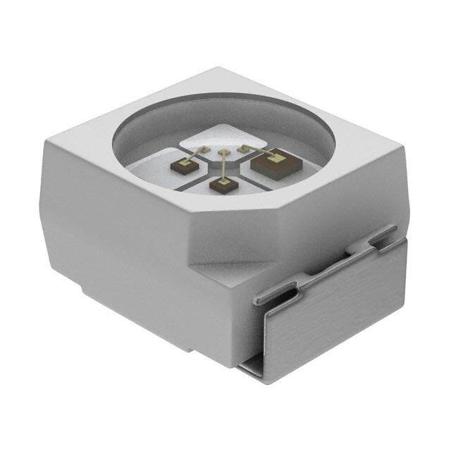
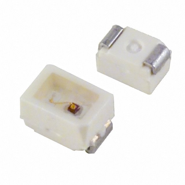
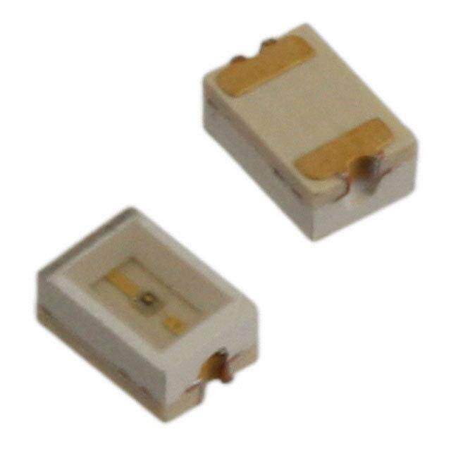
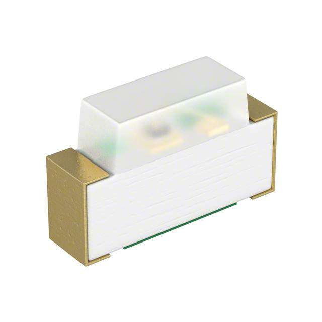
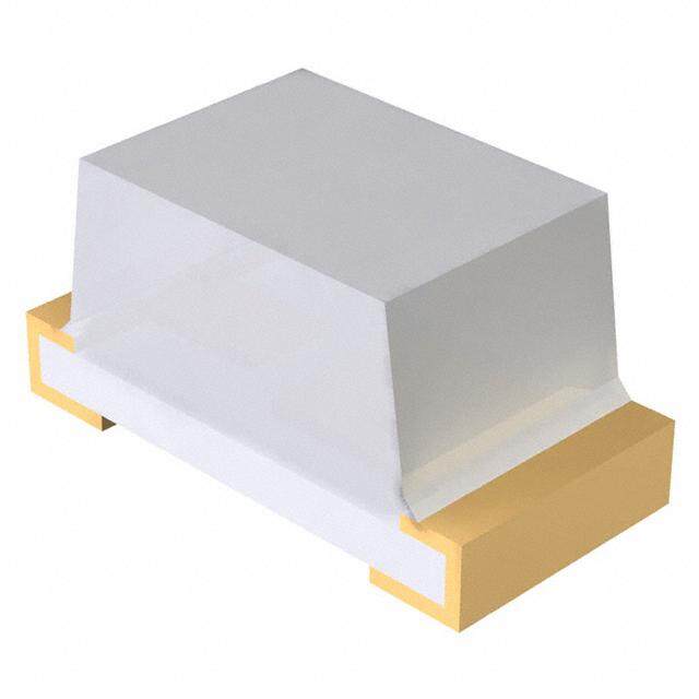
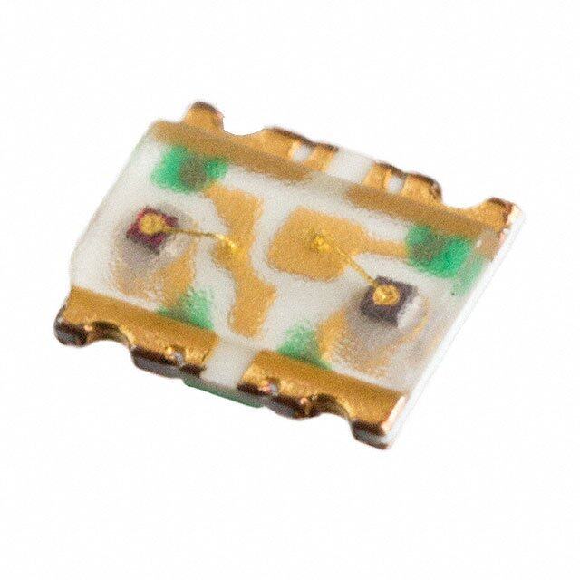
ICGOO电子元器件商城为您提供HSMG-C191由Avago Technologies设计生产,在icgoo商城现货销售,并且可以通过原厂、代理商等渠道进行代购。 HSMG-C191价格参考¥0.36-¥0.36。Avago TechnologiesHSMG-C191封装/规格:LED 指示 - 分立, 绿色 572nm LED 指示 - 分立 2.2V 0603(1608 公制)。您可以下载HSMG-C191参考资料、Datasheet数据手册功能说明书,资料中有HSMG-C191 详细功能的应用电路图电压和使用方法及教程。
Broadcom Limited 的 HSMG-C191 是一款 LED 指示 - 分立型元件,主要用于各种需要简单视觉指示的应用场景。以下是一些典型的应用领域:

 1. 消费电子产品
HSMG-C191 可用于消费电子设备中,如电视、音响、路由器等,作为电源状态、工作模式或故障提示的指示灯。它能够以低功耗和稳定的性能提供清晰的视觉反馈,帮助用户了解设备的工作状态。

 2. 工业控制设备
在工业自动化系统中,HSMG-C191 可以用作机器运行状态、报警信号或操作模式的指示灯。例如,在生产线上的控制器、传感器或开关设备中,LED 指示灯可以帮助操作人员快速判断设备是否正常工作,或者是否有异常情况发生。

 3. 通信设备
在网络通信设备中,如交换机、调制解调器、光纤收发器等,HSMG-C191 可以用于指示网络连接状态、数据传输速率或故障信息。通过不同的颜色或闪烁模式,LED 可以提供丰富的状态信息,帮助技术人员进行故障排查和维护。

 4. 汽车电子
在汽车内部,HSMG-C191 可以用于仪表盘、车门控制面板、空调系统等位置,作为功能指示灯。它可以显示车辆的各种状态,如车门未关、安全带未系、油量不足等,帮助驾驶员及时了解车辆的运行状况,确保行车安全。

 5. 医疗设备
在医疗仪器中,HSMG-C191 可以用于指示设备的工作状态、报警信息或患者的生命体征监测结果。例如,在心电监护仪、血压计、血糖仪等设备中,LED 指示灯可以为医护人员提供直观的操作指引和状态反馈,确保设备的正确使用。

 6. 智能家居
在智能家居系统中,HSMG-C191 可以用于智能插座、智能灯泡、安防摄像头等设备,作为工作状态或报警提示的指示灯。它可以通过不同的颜色或闪烁频率来表示设备的不同状态,方便用户远程监控和管理家庭设备。

总之,HSMG-C191 凭借其低功耗、高亮度和稳定性,广泛应用于各类需要简单视觉指示的场景,帮助用户和操作人员更直观地了解设备的状态和信息。
| 参数 | 数值 |
| 产品目录 | |
| 描述 | LED CHIP GAP GREEN TOP MOUNT标准LED-SMD GaP Green |
| 产品分类 | |
| LED大小 | 1.6 mm x 0.8 mm x 0.6 mm |
| 品牌 | Avago Technologies |
| 产品手册 | |
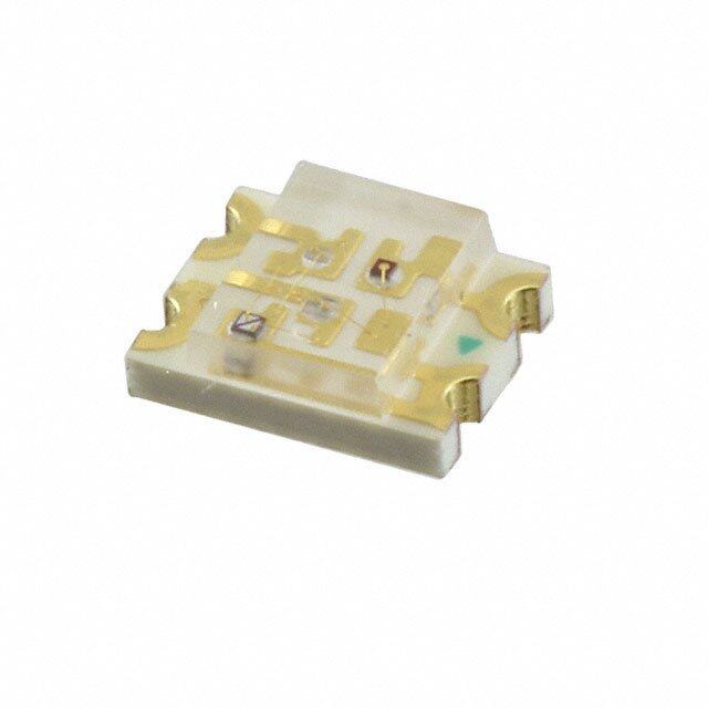
| 产品图片 |
|
| rohs | 符合RoHS无铅 / 符合限制有害物质指令(RoHS)规范要求 |
| 产品系列 | LED发射器,标准LED-SMD,Avago Technologies HSMG-C191- |
| 数据手册 | http://www.avagotech.com/docs/AV02-0551EN |
| 产品型号 | HSMG-C191 |
| 产品种类 | 标准LED-SMD |
| 光强度 | 15 mcd |
| 其它名称 | 516-2493-1 |
| 包装 | 剪切带 (CT) |
| 商标 | Avago Technologies |
| 大小/尺寸 | 1.60mm 长 x 0.80mm 宽 |
| 安装类型 | 表面贴装 |
| 封装 | Reel |
| 封装/外壳 | 0603(1608 公制) |
| 工厂包装数量 | 4000 |
| 显示角 | 170 deg |
| 最大工作温度 | + 85 C |
| 最小工作温度 | - 40 C |
| 标准包装 | 1 |
| 正向电压 | 2.2 V |
| 正向电流 | 20 mA |
| 毫烛光等级 | 15mcd |
| 波长-主 | 572nm |
| 波长-峰值 | 570nm |
| 波长/色温 | 572 nm |
| 测试电流时的光通量 | - |
| 照明颜色 | Green |
| 电压-正向(Vf)(典型值) | 2.2V |
| 电流-测试 | 20mA |
| 视角 | 170° |
| 透镜样式/尺寸 | 矩形,带平顶,1mm x 0.8mm |
| 透镜类型 | 散射 |
| 透镜颜色/类型 | Untinted Diffused |
| 颜色 | 绿 |
| 高度 | 0.60mm |


- 商务部:美国ITC正式对集成电路等产品启动337调查
- 曝三星4nm工艺存在良率问题 高通将骁龙8 Gen1或转产台积电
- 太阳诱电将投资9.5亿元在常州建新厂生产MLCC 预计2023年完工
- 英特尔发布欧洲新工厂建设计划 深化IDM 2.0 战略
- 台积电先进制程称霸业界 有大客户加持明年业绩稳了
- 达到5530亿美元!SIA预计今年全球半导体销售额将创下新高
- 英特尔拟将自动驾驶子公司Mobileye上市 估值或超500亿美元
- 三星加码芯片和SET,合并消费电子和移动部门,撤换高东真等 CEO
- 三星电子宣布重大人事变动 还合并消费电子和移动部门
- 海关总署:前11个月进口集成电路产品价值2.52万亿元 增长14.8%

PDF Datasheet 数据手册内容提取
HSMD-Cxxx, HSMG-Cxxx, HSMH-Cxxx, HSMS-Cxxx, HSMY-Cxxx, Surface Mount Chip LEDs Data Sheet HSMx-C110/ HSMx-C120/HSMx-C150/HSMx-C170/HSMx-C177/ HSMx-C190/HSMx-C191/HSMx-C197/HSMx-C265 Description Features These chip LEDs are designed in an industry standard Small size package for ease of handling and use. Various diff erent Industry standard footprint LED colors are available in nine compact, single color packages. Compatible with IR solder Diff used optics The HSMx-C150 has the industry standard 3.2 x 1.6 mm footprint that is excellent for all around use. The Operating temperature range of -40°C to +85°C HSMx-C170 has the widely used 2.0 x 1.25 mm foot-print Right angle & reverse mount package available with 0.8 mm profi le. The HSMx-C177 has the widely Various colors available used 2.0 x 1.25 mm footprint with 0.4 mm profi le. The HSMx-C19x series has the industry standard 1.6 x 0.8 mm Available in 8 mm tape on 7 in. (178 mm) diameter footprint with varying profi le to suit designers needs, reels the HSMx-C190 has 0.8 mm profi le, the HSMx-C191 has a low profi le of 0.6 mm, and the HSMx-C197 has the ultra Applications low profi le of 0.4 mm. This family with its thin profi le and wide viewing angle makes this LED exceptional for back- Keypad backlighting lighting applications. Push-button backlighting The HSMx-C110 is a right angle package with the uni- LCD backlighting versally accepted dimensions of 3.2 x 1.0 x 1.5 mm. The Symbol backlighting HSMx-C120 is a smaller right angle package with industry standard 1.6 x 0.6 x 1.0 mm. HSMx-C265 is a reverse Front panel indicator mount package with dimensions of 3.4 x 1.25 x 1.1 mm. These devices are ideal for LCD backlighting and side- lighting applications. In order to facilitate pick and place operation, these chip LEDs are shipped in tape and reel with 4000 units per reel for HSMx-C120, C170, C177, C190, C191, C197 packages, and 3000 units per reel for HSMx-C110, C150, C265 packages. All packages are compatible with IR reflow solder processes. The small size and wide viewing angle make these LEDs prime choices for backlighting applications and front panel illumination especially where space is a premium.
Device Selectiion Guide GaP Green HER Orange Yellow Description HSMG-C110 HSMS-C110 HSMD-C110 HSMY-C110 Untinted, Non-Diff used HSMG-C120 HSMS-C120 HSMD-C120 – Untinted, Non-Diff used HSMG-C150 HSMS-C150 HSMD-C150 HSMY-C150 Untinted, Diff used HSMG-C170 HSMS-C170 HSMD-C170 HSMY-C170 Untinted, Diff used HSMG-C177 HSMS-C177 HSMD-C177 HSMY-C177 Untinted, Diff used HSMG-C190 HSMS-C190 HSMD-C190 HSMY-C190 Untinted, Diff used HSMG-C191 HSMS-C191 HSMD-C191 HSMY-C191 Untinted, Diff used HSMG-C197 HSMS-C197 HSMD-C197 HSMY-C197 Untinted, Diff used HSMG-C265 – – – Untinted, Non-Diff used As AlGaAs Red Description HSMH-C110 Untinted, Non-Diff used HSMH-C120 Untinted, Non-Diff used HSMH-C150 Untinted, Diff used HSMH-C170 Untinted, Diff used HSMH-C190 Untinted, Diff used HSMH-C191 Untinted, Diff used HSMH-C265 Untinted, Non-Diff used Package Dimensions CATHODE (ANODE MARK FOR CATHODE (ANODE MARK FOR MARK HSMH-C170) MARK HSMH-C150) 1.6 (0.063) 1.25 (0.049) 2.0 (0.079 ) 3.2 (0.126 ) DIFFUSED 2.0 (0.079) POLARITY[3] DIFFUSED 1.4 POLARITY[3] EPOXY EPOXY (0.055) 0.6 (0.024) 0.3 (0.012) 1.1 (0.043) PC BOARD PC BOARD 0.8 (0.031) CATHODE LINE CATHODE LINE 0.3 (0.012) (ANODE LINE 0.5 (0.020) (ANODE LINE FOR HSMH-C150) FOR HSMH-C170) 0.50 ± 0.2 0.50 ± 0.2 (0.020 ± 0.008) 0.4 ± 0.15 0.4 ± 0.15 (0.020 ± 0.008) (0.016 ± 0.006) (0.016 ± 0.006) SOLDERING TERMINAL SOLDERING TERMINAL HSMx-C150 HSMx-C170 Notes: 1. All dimensions in millimeters (inches). 2. Tolerance is ±0.1 mm (±0.004 in.) unless otherwise specifi ed. 3. Polarity for HSMH-Cxxx will be the opposite of what is shown on above drawings. 2
CATHODE (ANODE MARK CATHODE MARK LED DIE LINE FOR HSMH-C110) (ANODE MARK FOR HSMH-C190) 1.0 (0.039) 0.8 (0.031) 2.6 (0.102 ) 1.6 (0.063 ) 3.2 (0.126 ) POLARITY[3] CLEAR 1.0 EPOXY (0.039) POLARITY[3] 0.3 (0.012) 1.5 (0.059) DIFFUSED EPOXY PC BOARD PC BOARD 0.5 (0.020) 1.6 (0.063 ) 0.8 (0.031) CATHODE LINE 0.3 (0.012) 3.2 (0.126 ) (ANODE LINE FOR HSMH-C190) CATHODE LINE 0.3 ± 0.15 0.3 ± 0.15 0.8 (0.031) (ANODE LINE (0.012 ± 0.006) (0.012 ± 0.006) FOR HSMH-C110) 1.0 (0.039) 0.7 (0.028) MIN. SOLDERING SOLDERING TERMINAL TERMINAL HSMx-C190 HSMx-C110 CATHODE MARK CATHODE MARK (ANODE MARK FOR HSMH-C191) 0.8 (0.031) 1.25 (0.049) 1.6 (0.063) 2.00 (0.079) 1.0 (0.039) POLARITY[3] POLARITY DIFFUSED EPOXY 0.40 (0.016) 0.3 (0.012) DIFFUSED EPOXY PC BOARD PC BOARD 0.16 (0.006) 0.6 (0.023) CATHODE LINE 0.3 (0.012) (ANODE LINE CATHODE LINE FOR HSMH-C191) 0.3 ± 0.15 0.3 ± 0.15 0.40 ± 0.15 0.40 ± 0.15 (0.012 ± 0.006) (0.012 ± 0.006) (0.016 ± 0.006) (0.016 ± 0.006) 0.7 (0.028) MIN. 1.10 (0.043) MIN. SOLDERING SOLDERING TERMINAL TERMINAL HSMx-C191 HSMx-C177 Notes: 1. All dimensions in millimeters (inches). 2. Tolerance is ±0.1 mm (±0.004 in.) unless otherwise specifi ed. 3. Polarity for HSMH-Cxxx will be the opposite of what is shown on above drawings. 3
3.4 (0.134) CATHODE MARK (ETCHED) CATHODE MARK [ANODE MARK FOR HSMH-C265] LED DIE 1.25 (0.049) 0.80 (0.031) GREEN SOLDER MASK 1.60 (0.063) POLARITY[3] 1.2 POLARITY UNDIFFUSED (0.047) DIFFUSED EPOXY EPOXY 1.1 (0.043) 1.1 (0.043) 0.40 (0.016) PC BOARD PC BOARD 0.16 (0.006) CATHODE LINE 0.3 (0.012) (ANODE LINE FOR HSMH-C265) CATHODE LINE 0.50 ± 0.15 0.50 ± 0.15 0.30 ± 0.15 (0.020 ± 0.006) (0.020 ± 0.006) (0.012 ± 0.006) 0.70 (0.028) MIN. SOLDERING SOLDERING TERMINAL TERMINAL HSMx-C265 HSMx-C197 CATHODE MARK LED DIE (ANODE MARK FOR HSMH-C120) 0.3 (0.012) 0.6 (0.024) 1.6 (0.063) POLARITY[3] 1.2 (0.047) CLEAR EPOXY 1.0 (0.039) PC BOARD 0.5 (0.020) CATHODE LINE 3 – 0.3 (0.012) (ANODE LINE FOR HSMH-C120) SOLDERING TERMINAL HSMx-C120 Notes: 1. All dimensions in millimeters (inches). 2. Tolerance is ±0.1 mm (±0.004 in.) unless otherwise specifi ed. 3. Polarity for HSMH-Cxxx will be the opposite of what is shown on above drawings. 4
Absolute Maximum Ratings for GaP at T =25°C A Parameter C110/150/265 C120/170/177/190/191/197 Units DC Forward Current[1] 25 20 mA Power Dissipation 65 52 mW Reverse Voltage (IR=100 μA) 5 5 V LED Junction Temperature 95 95 °C Operating Temperature Range -40 to +85 -40 to +85 °C Storage Temperature Range -40 to +85 -40 to +85 °C Soldering Temperature See refl ow soldering profi le (Figure 9 & 10) Absolute Maximum Ratings for AlGaAs at T =25°C A Parameter C110/150 C120/170/190/191/265 Units DC Forward Current[1] 30 25 mA Power Dissipation 78 65 mW Reverse Voltage (IR=100μA) 5 5 V LED Junction Temperature 95 95 °C Operating Temperature Range -40 to +85 -40 to +85 °C Storage Temperature Range -40 to +85 -40 to +85 °C Soldering Temperature See refl ow soldering profi le (Figure 9 & 10) Note: 1. Derate linearly as shown in Figure 4 for temperature above 25°C. Electrical Characteristics at T =25°C A Reverse Capacitance Forward Voltage Breakdown C(pF), Thermal Part Number Color V (Volts) V (Volts) @ V = 0 V, Resistance F R F @ IF = 20 mA @ IR = 100 μA f = 1 MHz RJ-P (°C/W) Typ. Max. Min. Typ. Typ. HSMS-C110/150 HER 2.1 2.6 5 5 400 HSMS-C120 350 HSMS-C170/177/190/191/197 250 HSMD-C110/150 Orange 2.2 2.6 5 7 400 HSMD-C120 350 HSMD-C170/177/190/191/197 250 HSMY-C110/150 Yellow 2.1 2.6 5 6 400 HSMY-C170/177/190/191/197 250 HSMG-C110/150 Green 2.2 2.6 5 9 400 HSMG-C120 350 HSMG-C170/177/190191/197/265 250 HSMH-C110/150 AlGaAs 1.8 2.6 5 18 460 HSMH-C120 400 HSMH-C170/190/191/265 300 5
Optical Characteristics at T =25°C A Luminous Peak Dominant Intensity[1] Wavelength Wavelength Viewing Part Number Color Iv(mcd)@20mA peak(nm) d(nm) Angle 21/2(°)[2] Min. Typ. Typ. Typ. Typ. HSMG-C110/177/197 Green 4.5 15.0 570 572 130 HSMG-C120 155 HSMG-C150/170/190/191/265 170 HSMS-C110/177/197 HER 2.8 10.0 630 626 130 HSMS-C120 155 HSMS-C150/170/190/191 170 HSMD-C110/177/197 Orange 2.8 8.0 605 604 130 HSMD-C120 155 HSMD-C150/170/190/191 170 HSMY-C110/177/197 Yellow 2.8 8.0 589 586 130 HSMY-C150/170/190/191 170 HSMH-C110 AlGaAs 7.2 17.0 660 639 130 HSMH-C120 155 HSMH-C150/170/190/191/265 170 Notes: 1. The luminous intensity, Iv, is measured at the peak of the spatial radiation pattern, which may not be aligned with the mechanical axis of the lamp package. 2. 1/2 is the off -axis angle where the luminous intensity is 1/2 the peak intensity. Color Bin Limits[1] Green Color Bins[1] Yellow Color Bins[1] Dom. Wavelength (nm) Dom. Wavelength (nm) Bin ID Min. Max. Bin ID Min. Max. A 561.5 564.5 A 582.0 584.5 B 564.5 567.5 B 584.5 587.0 C 567.5 570.5 C 587.0 589.5 D 570.5 573.5 D 589.5 592.0 E 573.5 576.5 E 592.0 594.5 Tolerance: ±1 nm F 594.5 597.0 Tolerance: ±1 nm Orange Color Bins[1] Dom. Wavelength (nm) Bin ID Min. Max. A 597.0 600.0 B 600.0 603.0 C 603.0 606.0 D 606.0 609.0 E 609.0 612.0 F 612.0 615.0 T olerance: ±1 nm 6
Light Intensity (Iv) Bin Limits[1] Intensity (mcd) Intensity (mcd) Bin ID Min. Max. Bin ID Min. Max. A 0.11 0.18 N 28.50 45.00 B 0.18 0.29 P 45.00 71.50 C 0.29 0.45 Q 71.50 112.50 D 0.45 0.72 R 112.50 180.00 E 0.72 1.10 S 180.00 285.00 F 1.10 1.80 T 285.00 450.00 G 1.80 2.80 U 450.00 715.00 Note: 1. Bin categories are established for classifi - H 2.80 4.50 V 715.00 1125.00 cation of products. Products may not be J 4.50 7.20 W 1125.00 1800.00 available in all categories. Please contact your Avago representative for information K 7.20 11.20 X 1800.00 2850.00 on currently available bins. L 11.20 18.00 Y 2850.00 4500.00 2. The Iv binning specifi cation set-up is for lowest allowable Iv binning only. There is M 18.00 28.50 no upper Iv bin limits. Tolerance: ±15% 1.0 GREEN AlGaAs Y T YELLOW SI N E T VE IN 0.5 ORANGE HER TI A L E R 0 500 550 600 650 700 750 WAVELENGTH – nm Figure 1. Relative intensity vs. wavelength. 100 1.6 A m 35 AlGaAs T – C110/C150 AlGaAs CH1E1R0, O/CR1A5N0G/CE2,65 A N 30 YELLOW, GREEN ORWARD CURRENT – m 101 AlGaAs HER GREEN UMINOUS INTENSITYORMALIZED AT 20 mA) 010...428 MUM FORWARD CURRE 21210550 CCCH111E279R071,///CCC111799007// CCC112296005// ACCl116G790Ra010Aq//CC°sJC11-A79/W77 =// I – FF YELLOW L(N GaP – MAXI 5 OYGERRLEALENONGWE,, 80R0q°JC-A/W = 0.11.5 1.7 ORAN1.G9E 2.1 2.3 00 10 20 30 40 F MAX. 00 20 40 60 80 100 VF – FORWARD VOLTAGE – V IF – FORWARD CURRENT – mA I TA – AMBIENT TEMPERATURE – °C Figure 2. Forward current vs. forward voltage. Figure 3. Luminous intensity vs. forward Figure 4. Maximum forward current vs. ambient current. temperature. 7
1.00 0.90 0.80 % Y – 0.70 T SI 0.60 N TE 0.50 N E I 0.40 V ATI 0.30 L RE 0.20 0.10 0 -90 -80 -70 -60 -50 -40 -30 -20 -10 0 10 20 30 40 50 60 70 80 90 ANGLE 1.00 0.90 0.80 % Y – 0.70 T SI 0.60 N TE 0.50 N E I 0.40 V ATI 0.30 L RE 0.20 0.10 0 -90 -80 -70 -60 -50 -40 -30 -20 -10 0 10 20 30 40 50 60 70 80 90 ANGLE Figure 5. Relative intensity vs. angle for HSMx-C110. 100 90 80 Y T 70 SI N E 60 T E IN 50 TIV 40 A EL 30 R 20 10 0 -90 -80 -70 -60 -50 -40 -30 -20 -10 0 10 20 30 40 50 60 70 80 90 ANGLE 100 90 80 Y T 70 SI N E 60 T E IN 50 TIV 40 A EL 30 R 20 10 0 -90 -80 -70 -60 -50 -40 -30 -20 -10 0 10 20 30 40 50 60 70 80 90 ANGLE Figure 6. Relative intensity vs. angle for HSMx-C120. 8
100 90 80 % Y – 70 T SI 60 N TE 50 N E I 40 V ATI 30 L RE 20 10 0 -90 -80 -70 -60 -50 -40 -30 -20 -10 0 10 20 30 40 50 60 70 80 90 ANGLE Figure 7. Relative intensity vs. angle for HSMx-C177 and C197. 1.00 0.90 0.80 % Y – 0.70 T SI 0.60 N TE 0.50 N E I 0.40 V ATI 0.30 L RE 0.20 0.10 0 -90 -80 -70 -60 -50 -40 -30 -20 -10 0 10 20 30 40 50 60 70 80 90 ANGLE Figure 8. Relative intensity vs. angle for HSMx-C150, C170, C190, C191 and C265. 10 SEC. MAX. 255 - 260 C URE 217 C 3 C/SEC. MAX. 10 SEC. MAX. AT 200 C R 6 C/SEC. MAX. E RE 230°C MAX. MP 150 C ATU 140-160°C 4°C/SEC. MAX. TE 3 C/SEC. MAX. R E P M 4°C/SEC. 3°C/SEC. MAX. 60 - 120 SEC. 60 SEC. MAX. TE MAX. OVER 2 MIN. TIME TIME Figure 9. Recommended refl ow soldering profi le. Figure 10. Recommended Pb-free refl ow soldering profi le. 0.8 (0.031) 1.5 (0.059) 1.2 (0.047) 1.2 1.2 (0.047) (0.047) 0.8 0.8 1.5 2.0 1.5 0.9 (0.031) (0.031) (0.059) (0.079) (0.059) (0.035) 0.7 (0.028) Figure 11. Recommended soldering pattern Figure 12. Recommended soldering Figure 13. Recommended soldering pattern for HSMx-C150. pattern for HSMx-C170 and C177. for HSMx-C190, C191 and C197. 9
5.0 (0.200) 0.9 (0.035) 0.4 (0.016) 0.9 (0.035) 0.4 (0.016) 1.0 (0.039) 0.7 (0.028) 0.2 (0.008) 0.15 (0.006) CENTERING CENTERING BOARD BOARD 1.5 2.0 1.5 0.8 1.2 0.8 (0.059) (0.079) (0.059) (0.031) (0.047) (0.031) Figure 14. Recommended soldering pattern for HSMx-C110. Figure 15. Recommended soldering pattern for HSMx-C120. USER FEED DIRECTION 2.2 (0.087) DIA. PCB HOLE CATHODE SIDE 1.25 (0.049) 1.4 2.3 1.4 PRINTED LABEL (0.055) (0.091) (0.055) Figure 16. Recommended soldering pattern for HSMx-C265. Figure 17. Reeling orientation. 8.0 ± 1.0 (0.315 ± 0.039) 10.50 ± 1.0 (0.413 ± 0.039) Ø 13.1 ± 0.5 (Ø 0.516 ± 0.020) Ø 20.20 MIN. (Ø 0.795 MIN.) 3.0 ± 0.5 (0.118 ± 0.020) 178.40 ± 1.00 59.60 ± 1.00 (7.024 ± 0.039) (2.346 ± 0.039) 4.0 ± 0.5 5.0 ± 0.5 (0.157 ± 0.020) (0.197 ± 0.020) 6 PS Figure 18. Reel dimensions. Note: All dimensions in millimeters (inches). 10
DIM. C 4.00 (0.157) CATHODE (SEE TABLE 1) 1.50 (0.059) 0.20 ± 0.05 (0.008 ± 0.002) 1.75 (0.069) 3.50 ± 0.05 (0.138 ± 0.002) DIM. A (SEE TABLE 1) 8.00 ± 0.30 (0.315 ± 0.012) DIM. B CARRIER TAPE (SEE TABLE 1) USER FEED 2.00 ± 0.05 DIRECTION COVER TAPE (0.079 ± 0.002) 4.00 (0.157) TABLE 1 DIMENSIONS IN MILLIMETERS (INCHES) DIM. A DIM. B DIM. C HSMx-C110/C120 PART NUMBER ± 0.10 (0.004) ± 0.10 (0.004) ± 0.10 (0.004) POSITION IN HSMx-C110 SERIES 3.40 (0.134) 1.70 (0.067) 1.20 (0.047) CARRIER TAPE HSMx-C120 SERIES 1.90 (0.075) 1.15 (0.045) 0.75 (0.030) HSMx-C150 SERIES 3.50 (0.138) 1.88 (0.074) 1.27 (0.050) DIM. A HSMx-C170 SERIES 2.30 (0.091) 1.45 (0.057) 0.95 (0.037) (SEE TABLE 1) HSMx-C177 SERIES 2.30 (0.091) 1.40 (0.055) 0.60 (0.024) HSMx-C190 SERIES 1.75 (0.069) 0.90 (0.035) 0.90 (0.035) HSMx-C191 SERIES 1.86 (0.073) 0.89 (0.035) 0.87 (0.034) HSMx-C197 SERIES 1.75 (0.069) 0.95 (0.037) 0.60 (0.024) DIM. B R 1.0 ± 0.05 (SEE TABLE 1) (0.039 ± 0.002) R 0.5 ± 0.05 (0.020 ± 0.002) DIM. C 4.00 (0.157) CATHODE (SEE TABLE 1) 1.50 (0.059) 0.20 ± 0.05 (0.008 ± 0.002) 1.75 (0.069) 3.50 ± 0.05 (0.138 ± 0.002) DIM. A (SEE TABLE 1) 8.00 ± 0.30 (0.315 ± 0.012) DIM. B CARRIER TAPE (SEE TABLE 1) USER FEED 2.00 ± 0.05 DIRECTION COVER TAPE (0.079 ± 0.002) 4.00 (0.157) TABLE 1 DIMENSIONS IN MILLIMETERS (INCHES) DIM. A DIM. B DIM. C PART NUMBER ± 0.10 (0.004) ± 0.10 (0.004) ± 0.10 (0.004) HSMx-C265 SERIES 3.70 (0.146) 1.45 (0.057) 1.30 (0.051) Figure 19. Tape dimensions. 11
END START Storage Condition: 5 to 30˚ C @ 60% RH max. Baking is required under the condition: a) Humidity Indicator Card is >10% when read at 23 ± 5°C. b) Device exposed to factory conditions <30°C/60% RH more than 672 hours. THERE SHALL BE A MOUNTED WITH THERE SHALL BE A MINIMUM OF MINIMUM OF 160 mm COMPONENTS MINIMUM OF 160 mm 230 mm (6.3 INCH) OF EMPTY (6.3 INCH) OF EMPTY (9.05 INCH) Baking recommended condition: 60 COMPONENT POCKETS COMPONENT POCKETS MAY CONSIST +/– 5˚C for 20 hours. SEALED WITH COVER SEALED WITH COVER OF CARRIER TAPE. TAPE. AND/OR COVER TAPE. Figure 20. Tape leader and trailer dimensions. Convective IR Refl ow Soldering For more information on IR refl ow Notes: soldering, refer to Application Note 1. All dimensions in millimeters (inches). 1060, Surface Mounting SMT LED 2. Tolerance is ±0.1 mm (±0.004 in.)unless otherwise specifi ed. Indicator Components. For product information and a complete list of distributors, please go to our website: www.avagotech.com Avago, Avago Technologies, and the A logo are trademarks of Avago Technologies in the United States and other countries. Data subject to change. Copyright © 2005-2012 Avago Technologies. All rights reserved. Obsoletes 5989-4806EN AV02-0551EN - March 5, 2012