ICGOO在线商城 > 光电元件 > 显示器模块 - LED 字符与数字 > HDSP-7511
/HDSP-7511.jpg)
 Datasheet下载
- 型号: HDSP-7511
- 制造商: Avago Technologies
- 库位|库存: xxxx|xxxx
- 要求:
| 数量阶梯 | 香港交货 | 国内含税 |
| +xxxx | $xxxx | ¥xxxx |
查看当月历史价格
查看今年历史价格
HDSP-7511产品简介:
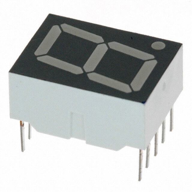
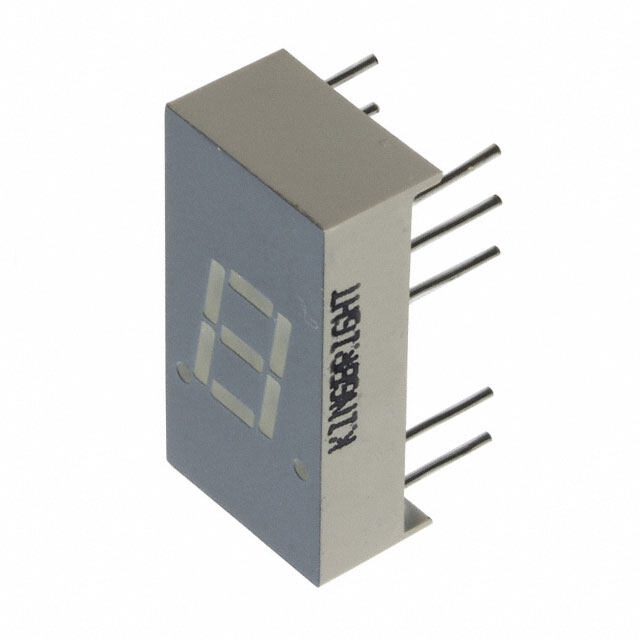
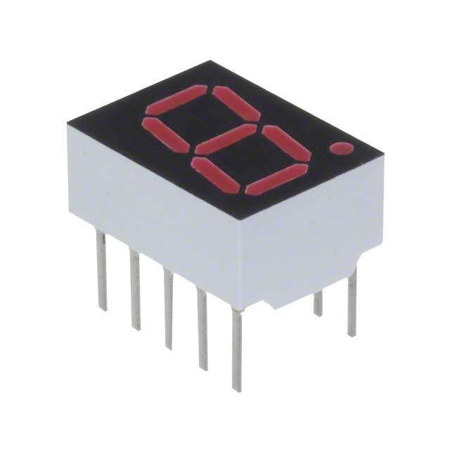
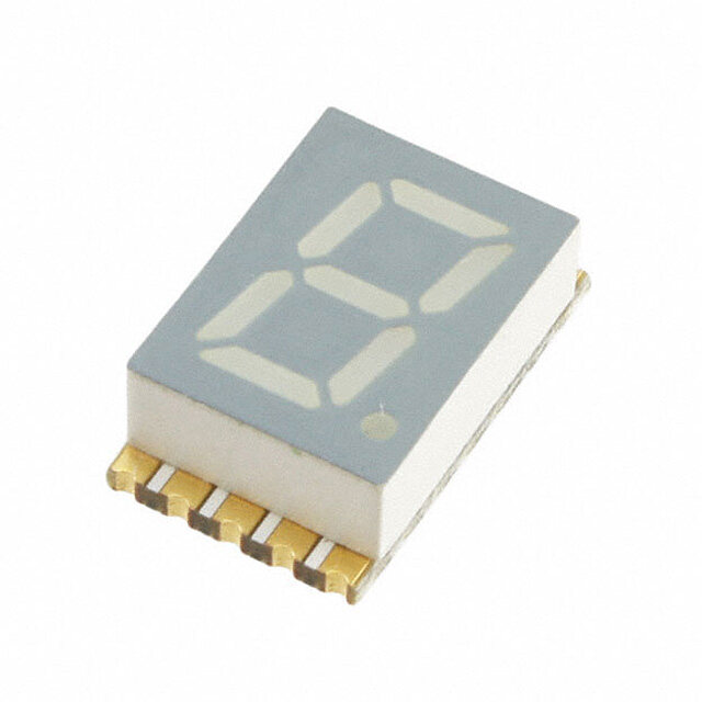
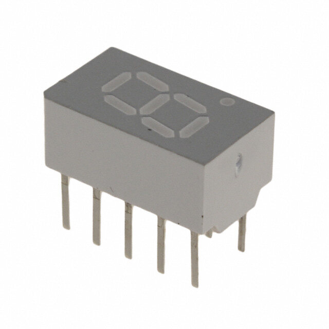
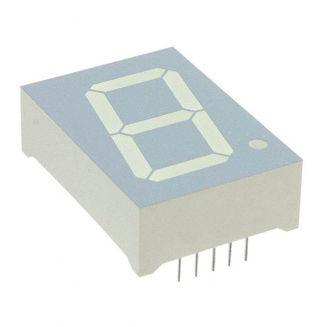
ICGOO电子元器件商城为您提供HDSP-7511由Avago Technologies设计生产,在icgoo商城现货销售,并且可以通过原厂、代理商等渠道进行代购。 HDSP-7511价格参考。Avago TechnologiesHDSP-7511封装/规格:显示器模块 - LED 字符与数字, Character LED Display Module Red 7-Segment 1 Character Common Anode 1.7V 5mA 0.500" H x 0.300" W x 0.390" D (12.70mm x 7.62mm x 9.91mm) 10-DIP (0.200", 5.08mm)。您可以下载HDSP-7511参考资料、Datasheet数据手册功能说明书,资料中有HDSP-7511 详细功能的应用电路图电压和使用方法及教程。
Broadcom Limited 的型号 HDSP-7511 属于显示器模块 - LED 字符与数字类别,其主要应用场景包括以下方面:

1. 工业控制面板:HDSP-7511 可用于工业设备的控制面板中,显示温度、压力、流量等关键参数。其高亮度和清晰度确保在不同光照条件下仍能准确读取数据。

2. 测量仪器:该模块适用于各种测量仪器,例如万用表、频率计或信号发生器,用于实时显示数值结果,提供直观的数据反馈。

3. 家用电器:在一些高端家用电器(如微波炉、烤箱、洗衣机)中,HDSP-7511 可作为数字显示屏,用于显示时间、温度或运行状态等信息。

4. 通信设备:在通信领域,此模块可用于基站监控设备或网络测试仪上,显示信号强度、信道编号或其他技术指标。

5. 汽车电子:HDSP-7511 能够集成到车载系统中,例如显示车速、油量或故障代码等信息,为驾驶员提供必要的操作参考。

6. 安防监控:在安防设备中,该模块可用于显示摄像头编号、时间戳或报警状态,便于用户快速获取重要信息。

7. 金融终端:POS 机、ATM 或其他金融终端设备中,HDSP-7511 可以用来显示交易金额、余额或确认信息,保证数据的精确性和可视性。

8. 医疗设备:在医疗仪器(如血压计、心率监测仪)中,该模块能够清晰地显示患者的生命体征数据,帮助医护人员进行诊断和治疗。

9. 环境监测:用于空气检测仪、水质分析仪等设备中,显示污染指数、湿度、温度等环境参数,支持环保领域的应用需求。

总结来说,HDSP-7511 凭借其高可靠性、低功耗和出色的显示性能,在需要字符或数字显示的各种场景中具有广泛的应用价值。
| 参数 | 数值 |
| 产品目录 | |
| 描述 | LED 7-SEG 7.6MM CA HE RED RHDLED 显示器和配件 Red 626nm 0.3in 7 Segment |
| 产品分类 | |
| 品牌 | Avago Technologies |
| 产品手册 | http://www.avagotech.com/pages/en/led_displays/through-hole_seven_segment_displays/0.3_single_digit_series/hdsp-7511/ |
| 产品图片 |
|
| rohs | 符合RoHS无铅 / 符合限制有害物质指令(RoHS)规范要求 |
| 产品系列 | LED 显示器和配件,Avago Technologies HDSP-7511- |
| 数据手册 | |
| 产品型号 | HDSP-7511 |
| 产品目录绘图 |
|
| 产品目录页面 | |
| 产品种类 | LED 显示器和配件 |
| 光强度 | 270 ucd |
| 共用管脚 | Common Anode |
| 其它名称 | 516-1222-5 |
| 功率耗散(最大值) | 52mW |
| 商标 | Avago Technologies |
| 大小/尺寸 | 0.500" 高 x 0.300" 宽 x 0.390" 直径(12.70mm x 7.62mm x 9.91mm) |
| 字符大小 | 7.6 mm |
| 字符数 | 1 |
| 安装风格 | Through Hole |
| 封装 | Tube |
| 封装/外壳 | 10-DIP(0.200",5.08mm) |
| 工作电流 | 2 mA |
| 工作电源电压 | 1.7 V |
| 工厂包装数量 | 200 |
| 数位数量 | 1 |
| 数字/字母大小 | 0.30"(7.62mm) |
| 显示器类型 | 7 Segment |
| 显示类型 | 7 段显示 |
| 最大工作温度 | + 100 C |
| 最小工作温度 | - 20 C |
| 标准包装 | 200 |
| 正向电压 | 1.7 V |
| 正向电流 | 2 mA |
| 毫烛光等级 | 1.05mcd |
| 波长 | 645 nm |
| 波长-峰值 | 635nm |
| 照明颜色 | Red |
| 电压-正向(Vf)(典型值) | 1.7V |
| 电流-测试 | 5mA |
| 通用引脚 | 共阳极 |
| 配置 | Common Anode |
| 颜色 | 红 |


- 商务部:美国ITC正式对集成电路等产品启动337调查
- 曝三星4nm工艺存在良率问题 高通将骁龙8 Gen1或转产台积电
- 太阳诱电将投资9.5亿元在常州建新厂生产MLCC 预计2023年完工
- 英特尔发布欧洲新工厂建设计划 深化IDM 2.0 战略
- 台积电先进制程称霸业界 有大客户加持明年业绩稳了
- 达到5530亿美元!SIA预计今年全球半导体销售额将创下新高
- 英特尔拟将自动驾驶子公司Mobileye上市 估值或超500亿美元
- 三星加码芯片和SET,合并消费电子和移动部门,撤换高东真等 CEO
- 三星电子宣布重大人事变动 还合并消费电子和移动部门
- 海关总署:前11个月进口集成电路产品价值2.52万亿元 增长14.8%
PDF Datasheet 数据手册内容提取
HDSP Series Low Current Seven Segment Displays Data Sheet HDSP-335x Series, HDSP-555x Series HDSP-751x Series, HDSP-A10x Series HDSP-A80x Series, HDSP-A90x Series HDSP-E10x Series, HDSP-F10x Series HDSP-G10x Series, HDSP-H10x Series HDSP-K12x, K70x Series, HDSP-N10x Series Description Features These low current seven segment displays are designed • Low Power Consumption for applications requiring low power consumption. • Industry Standard Size They are tested and selected for their excellent low current characteristics to ensure that the segments are • Industry Standard Pinout matched at low currents. Drive currents as low as 1 • Choice of Character Size mA per segment are available. 7.6 mm (0.30 in), 10 mm (0.40 in), 10.9 mm (0.43 Pin for pin equivalent displays are also available in a in), 14.2 mm (0.56 in), 20 mm (0.80 in) standard current or high light ambient design. The • Choice of Colors standard current displays are available in all colors and are ideal for most applications. The high light ambient AlGaAs Red, High Efficiency Red (HER), Yellow, displays are ideal for sunlight ambients or long string Green lengths. For additional information see the 7.6 mm • Excellent Appearance Micro Bright Seven Segment Displays, 10 mm Seven Segment Displays, 7.6 mm/10.9 mm Seven Segment Evenly Lighted Segments Displays, 14.2 mm Seven Segment Displays, 20 mm ±50° Viewing Angle Seven Segment Displays, or High Light Ambient Seven Segment Displays data sheets. • Design Flexibility Common Anode or Common Cathode Single and Dual Digit Left and Right Hand Decimal Points ±1. Overflow Character • Categorized for Luminous Intensity Yellow and Green Categorized for Color Use of Like Categories Yields a Uniform Display • Excellent for Long Digit String Multiplexing
Devices AlGaAs HER Yellow Green Package HDSP- HDSP- HDSP- HDSP- Description Drawing A101 7511 A801 A901 7.6 mm Common Anode Right Hand Decimal A A103 7513 A803 A903 7.6 mm Common Cathode Right Hand Decimal B A107 7517 A807 A907 7.6 mm Common Anode ±1. Overflow C A108 7518 A808 A908 7.6 mm Common Cathode ±1. Overflow D F101 10 mm Common Anode Right Hand Decimal E F103 10 mm Common Cathode Right Hand Decimal F F107 10 mm Common Anode ±1. Overflow G F108 10 mm Common Cathode ±1. Overflow H G101 10 mm Two Digit Common Anode Right Hand Decimal X G103 10 mm Two Digit Common Cathode Right Hand Decimal Y E100 3350 10.9 mm Common Anode Left Hand Decimal I E101 3351 10.9 mm Common Anode Right Hand Decimal J E103 3353 10.9 mm Common Cathode Right Hand Decimal K E106 3356 10.9 mm Universal ±1. Overflow[1] L H101 5551 14.2 mm Common Anode Right Hand Decimal M H103 5553 14.2 mm Common Cathode Right Hand Decimal N H107 5557 14.2 mm Common Anode ±1. Overflow O H108 5558 14.2 mm Common Cathode ±1. Overflow P K121 K701 14.2 mm Two Digit Common Anode Right Hand Decimal R K123 K703 14.2 mm Two Digit Common Cathode Right Hand Decimal S N100 20 mm Common Anode Left Hand Decimal Q N101 20 mm Common Anode Right Hand Decimal T N103 20 mm Common Cathode Right Hand Decimal U N105 20 mm Common Cathode Left Hand Decimal V N106 20 mm Universal ±1. Overflow[1] W Note: 1. Universal pinout brings the anode and cathode of each segment’s LED out to separate pins. See internal diagrams L or W. 2
Part Numbering System 5082 - x xx x - x x x xx HDSP - x xx x - x x x xx Mechanical Options[1] 00: No mechanical option Color Bin Options[1,2] 0: No color bin limitation Maximum Intensity Bin[1,2] 0: No maximum intensity bin limitation Minimum Intensity Bin[1,2] 0: No minimum intensity bin limitation Device Configuration/Color[1] G: Green Device Specific Configuration[1] Refer to respective datasheet Package[1] Refer to Respective datasheet Notes: 1. For codes not listed in the figure above, please refer to the respective datasheet or contact your nearest Agilent representative for details. 2. Bin options refer to shippable bins for a part-number. Color and Intensity Bins are typically restricted to 1 bin per tube (exceptions may apply). Please refer to respective datasheet for specific bin limit information. 3
Package Dimensions 4
Package Dimensions (cont.) 5
Package Dimensions (cont.) *The Side View of package indicates Country of Origin. 6
Package Dimensions (cont.) 7
Package Dimensions (cont.) 8
Package Dimensions (cont.) 9
Internal Circuit Diagram 10
Internal Circuit Diagram (cont.) Absolute Maximum Ratings AlGaAs Red - HDSP- HER A10X/E10X/H10X HDSP-751X/ Yellow Green K12X/N10X/ 335X/555X/ HDSP-A80X HDSP-A90X Description F10X, G10X Series K70X Series Series Series Units Average Power per Segment or DP 37 52 64 mW Peak Forward Current per 45 mA Segment or DP DC Forward Current per 15[1] 15[2] mA Segment or DP Operating Temperature Range -20 to +100 -40 to +100 °C Storage Temperature Range -55 to +100 °C Reverse Voltage per Segment 3.0 V or DP Wave Soldering Temperature for 3 Seconds (1.60 mm [0.063 in.] 250 °C below seating body) Notes: 1. Derate above 91°C at 0.53 mA/°C. 2. Derate HER/Yellow above 80°C at 0.38 mA/°C and Green above 71°C at 0.31 mA/°C. 11
Electrical/Optical Characteristics at T = 25°C A AlGaAs Red Device Series HDSP- Parameter Symbol Min. Typ. Max. Units Test Conditions 315 600 I = 1 mA F A10x 3600 I = 5 mA F 330 650 I = 1 mA F F10x, G10x 3900 I = 5 mA F 390 650 I = 1 mA F E10x Luminous Intensity/Segment[1,2] I µcd V (Digit Average) 3900 I = 5 mA F 400 700 I = 1 mA F H10x, K12x 4200 I = 5 mA F 270 590 I = 1 mA F N10x 3500 I = 5 mA F 1.6 I = 1 mA F Forward Voltage/Segment or DP V 1.7 V I = 5 mA F F 1.8 2.2 I = 20 mA Pk F All Devices Peak Wavelength λPEAK 645 nm Dominant Wavelength[3] λd 637 nm Reverse Voltage/Segment or DP[4] V 3.0 15 V I = 100 µA R R Temperature Coefficient of ∆VF/°C -2 mV mV/°C V /Segment or DP F A10x 255 F10x, G10x 320 E10x 340 Thermal Resistance LED RθJ-PIN °C/W/Seg H10x, K12x Junction-to-Pin 400 N10x 430 12
High Efficiency Red Device Series HDSP- Parameter Symbol Min. Typ. Max. Units Test Conditions 160 270 I = 2 mA F 751x 1050 I = 5 mA F 200 300 I = 2 mA F Luminous Intensity/Segment[1,2] IV µcd (Digit Average) 1200 I = 5 mA F 335x, 555x, K70x 270 370 I = 2 mA F 1480 I = 5 mA F 1.6 I = 2 mA F Forward Voltage/Segment or DP V 1.7 V I = 5 mA F F 2.1 2.5 I = 20 mA Pk F All Devices Peak Wavelength λPEAK 635 nm Dominant Wavelength[3] λd 626 nm Reverse Voltage/Segment or DP[4] V 3.0 30 V I = 100 µA R R Temperature Coefficient of ∆VF/°C -2 mV/°C V /Segment or DP F 751x 200 335x Thermal Resistance LED RθJ-PIN 280 °C/W Junction-to-Pin 555x, K70x 345 13
Yellow Device Series HDSP- Parameter Symbol Min. Typ. Max. Units Test Conditions Luminous Intensity/Segment[1,2] 250 420 I = 4 mA F (Digit Average) IV µcd 1300 I = 10 mA F 1.7 I = 4 mA F Forward Voltage/Segment or DP V 1.8 V I = 5 mA F F A80x 2.1 2.5 I = 20 mA Pk F Peak Wavelength λPEAK 583 nm Dominant Wavelength[3,5] λd 581.5 585 592.5 nm Reverse Voltage/Segment or DP[4] V 3.0 30 V I = 100 µA R R Temperature Coefficient of ∆VF/°C -2 mV/°C V /Segment or DP F Thermal Resistance LED RθJ-PIN 200 °C/W Junction-to-Pin Green Device Series HDSP- Parameter Symbol Min. Typ. Max. Units Test Conditions Luminous Intensity/Segment[1,2] 250 475 I = 4 mA F (Digit Average) IV µcd 1500 I = 10 mA F 1.9 I = 4 mA F Forward Voltage/Segment or DP V 2.0 V I = 10 mA F F A90x 2.1 2.5 I = 20 mA Pk F Peak Wavelength λPEAK 566 nm Dominant Wavelength[3,5] λd 571 577 nm Reverse Voltage/Segment or DP[4] V 3.0 30 V I = 100 µA R R Temperature Coefficient of ∆VF/°C -2 mV/°C V /Segment or DP F Thermal Resistance LED RθJ-PIN 200 °C/W Junction-to-Pin Notes: 1. Device case temperature is 25°C prior to the intensity measurement. 2. The digits are categorized for luminous intensity. The intensity category is designated by a letter on the side of the package. 3. The dominant wavelength, ld, is derived from the CIE chromaticity diagram and is the single wavelength which defines the color of the device. 4. Typical specification for reference only. Do not exceed absolute maximum ratings. 5. The yellow (HDSP-A800) and Green (HDSP-A900) displays are categorized for dominant wavelength. The category is designated by a number adjacent to the luminous intensity category letter. 14
AlGaAs Red Figure 1. Maximum Allowable Average or Figure 2. Forward Current vs. Forward DC Current vs. Ambient Temperature. Voltage. Figure 3. Relative Luminous Intensity vs. Figure 4. Relative Efficiency (Luminous DC Forward Current. Intensity per Unit Current) vs. Peak Current. 15
HER, Yellow, Green Figure 5. Maximum Allowable Average or Figure 6. Forward Current vs. Forward DC Current vs. Ambient Temperature. Voltage. Figure 7. Relative Luminous Intensity vs. Figure 8. Relative Efficiency (Luminous DC Forward Current. Intensity per Unit Current) vs. Peak Current. 16
Intensity Bin Limits (mcd) AlGaAs Red HDSP-A10x IV Bin Category Min. Max. E 0.315 0.520 F 0.428 0.759 G 0.621 1.16 H 0.945 1.71 I 1.40 2.56 J 2.10 3.84 K 3.14 5.75 L 4.70 8.55 HDSP-E10x/F10x/G10x IV Bin Category Min. Max. D 0.391 0.650 E 0.532 0.923 F 0.755 1.39 G 1.13 2.08 H 1.70 3.14 HDSP-H10x/K12x IV Bin Category Min. Max. C 0.415 0.690 D 0.565 0.990 E 0.810 1.50 F 1.20 2.20 G 1.80 3.30 H 2.73 5.00 I 4.09 7.50 HDSP-N10x IV Bin Category Min. Max. A 0.270 0.400 B 0.325 0.500 C 0.415 0.690 D 0.565 0.990 E 0.810 1.50 F 1.20 2.20 G 1.80 3.30 H 2.73 5.00 I 4.09 7.50 17
Intensity Bin Limits (mcd), continued HER HDSP-751x IV Bin Category Min. Max. B 0.160 0.240 C 0.200 0.300 D 0.250 0.385 E 0.315 0.520 F 0.428 0.759 G 0.621 1.16 HDSP-335x IV Bin Category Min. Max. B 0.240 0.366 C 0.300 0.477 D 0.391 0.650 E 0.532 0.923 F 0.755 1.39 G 1.13 2.08 H 1.70 3.14 HDSP-555x/K70x IV Bin Category Min. Max. A 0.270 0.400 B 0.325 0.500 C 0.415 0.690 D 0.565 0.990 E 0.810 1.50 F 1.20 2.20 G 1.80 3.30 H 2.73 5.00 I 4.09 7.50 18
Intensity Bin Limits (mcd), continued Yellow HDSP-A80x IV Bin Category Min. Max. D 0.250 0.385 E 0.315 0.520 F 0.425 0.760 G 0.625 1.14 H 0.940 1.70 I 1.40 2.56 J 2.10 3.84 K 3.14 5.76 L 4.71 8.64 M 7.07 13.00 N 10.60 19.40 O 15.90 29.20 P 23.90 43.80 Q 35.80 65.60 Green HDSP-A90x IV Bin Category Min. Max. E 0.315 0.520 F 0.425 0.760 G 0.625 1.14 H 0.940 1.70 I 1.40 2.56 J 2.10 3.84 K 3.14 5.76 L 4.71 8.64 M 7.07 13.00 N 10.60 19.40 O 15.90 29.20 P 23.90 43.80 Q 35.80 65.60 19
Color Categories Dominant Wavelength (nm) Color Bin Min. Max. Yellow 1 581.50 585.00 3 584.00 587.50 2 586.50 590.00 4 589.00 592.50 Green 2 573.00 577.00 3 570.00 574.00 4 567.00 571.00 5 564.00 568.00 Note: All categories are established for classification of products. Products may not be available in all categories. Please contact your local Agilent representatives for further clarification/information. Electrical/Optical For more information on electrical/optical characteristics, please see Application Note 1005. Contrast Enhancement For information on contrast enhancement, please see Application Note 1015. Soldering/Cleaning Cleaning agents from the ketone family (acetone, methyl ethyl ketone, etc.) and from the chorinated hydrocarbon family (methylene chloride, trichloro- ethylene, carbon tetrachloride, etc.) are not recommended for cleaning LED parts. All of these various solvents attack or dissolve the encapsulating epoxies used to form the package of plastic LED parts. For information on soldering LEDs, please refer to Application Note 1027. For product information and a complete list of distributors, please go to our web site: www.avagotech.com Avago, Avago Technologies, and the A logo are trademarks of Avago Technologies, Pte. in the United States and other countries. Data subject to change. Copyright © 2006 Avago Technologies Pte. All rights reserved. Obsoletes 5989-2824EN 5989-3880EN - April 12, 2006