ICGOO在线商城 > 光电元件 > 显示器模块 - LED 字符与数字 > HDSP-7501
/HDSP-7501.jpg)
 Datasheet下载
- 型号: HDSP-7501
- 制造商: Avago Technologies
- 库位|库存: xxxx|xxxx
- 要求:
| 数量阶梯 | 香港交货 | 国内含税 |
| +xxxx | $xxxx | ¥xxxx |
查看当月历史价格
查看今年历史价格
HDSP-7501产品简介:
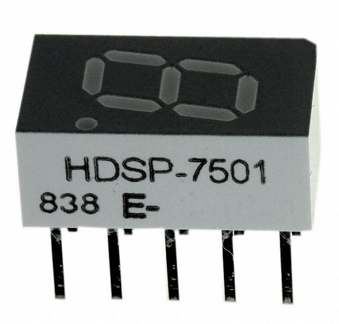
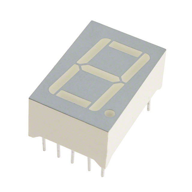
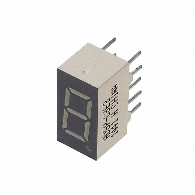
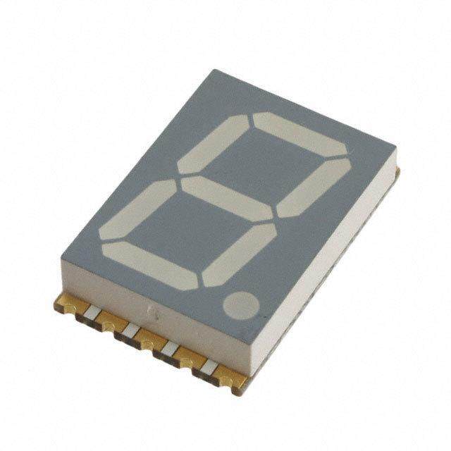
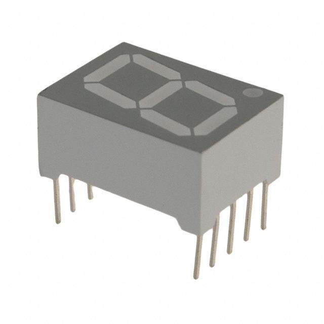
ICGOO电子元器件商城为您提供HDSP-7501由Avago Technologies设计生产,在icgoo商城现货销售,并且可以通过原厂、代理商等渠道进行代购。 HDSP-7501价格参考。Avago TechnologiesHDSP-7501封装/规格:显示器模块 - LED 字符与数字, Character LED Display Module Red 7-Segment 1 Character Common Anode 2V 20mA 0.500" H x 0.300" W x 0.240" D (12.70mm x 7.62mm x 6.09mm) 10-DIP (0.200", 5.08mm)。您可以下载HDSP-7501参考资料、Datasheet数据手册功能说明书,资料中有HDSP-7501 详细功能的应用电路图电压和使用方法及教程。
Broadcom Limited的HDSP-7501是一款显示器模块,属于LED字符与数字显示类别。这款产品主要应用于需要清晰、可靠地显示字符和数字信息的场景中。以下是一些典型的应用场景:

 1. 工业控制面板
   HDSP-7501可以用于工业自动化设备的控制面板上,显示设备的运行状态、温度、压力、流量等关键参数。其高亮度和清晰度使得即使在光线较强的环境中,操作人员也能轻松读取数据,确保生产过程的安全性和效率。

 2. 测量仪器
   在各种测量仪器中,如万用表、示波器、频谱分析仪等,HDSP-7501可以作为显示屏,实时显示测量结果。它能够快速响应并准确呈现数值变化,帮助技术人员进行精确的测量和分析。

 3. 通信设备
   在通信基站、路由器、交换机等网络设备中,HDSP-7501可以用来显示设备的工作状态、信号强度、IP地址等信息。它的稳定性和低功耗特性使其非常适合长时间运行的通信设备。

 4. 家用电器
   家用电器如微波炉、洗衣机、空调等也可以使用HDSP-7501来显示工作模式、时间、温度等信息。其简洁的界面设计和易于读取的特点,提升了用户的操作体验。

 5. 车载设备
   在汽车仪表盘或导航系统中,HDSP-7501可以用来显示车速、油量、里程等重要信息。它能够在不同的光照条件下保持良好的可视性,确保驾驶员能够及时获取车辆状态。

 6. 医疗设备
   医疗设备如心电图机、血压计、血糖仪等也可能会使用HDSP-7501来显示检测结果。它能够提供清晰、稳定的数据显示,帮助医护人员快速做出诊断。

总的来说,HDSP-7501凭借其高亮度、低功耗、稳定性和可靠性,广泛适用于各种需要清晰、实时显示字符和数字信息的场景。无论是工业、商业还是消费领域,它都能为用户提供高效、直观的信息展示解决方案。
| 参数 | 数值 |
| 产品目录 | |
| 描述 | LED 7-SEG 7.6MM CA HE RED RHDLED 显示器和配件 Red 626nm 0.3in 7 Segment |
| 产品分类 | |
| 品牌 | Avago Technologies |
| 产品手册 | http://www.avagotech.com/pages/en/led_displays/through-hole_seven_segment_displays/0.3_single_digit_series/hdsp-7501/ |
| 产品图片 |
|
| rohs | 符合RoHS无铅 / 符合限制有害物质指令(RoHS)规范要求 |
| 产品系列 | LED 显示器和配件,Avago Technologies HDSP-7501- |
| 数据手册 | |
| 产品型号 | HDSP-7501 |
| 产品目录绘图 |
|
| 产品目录页面 | |
| 产品种类 | LED 显示器和配件 |
| 光强度 | 980 ucd |
| 共用管脚 | Common Anode |
| 其它名称 | 516-1202-5 |
| 功率耗散(最大值) | 105mW |
| 商标 | Avago Technologies |
| 大小/尺寸 | 0.500" 高 x 0.300" 宽 x 0.240" 直径(12.70mm x 7.62mm x 6.09mm) |
| 字符大小 | 7.6 mm |
| 字符数 | 1 |
| 安装风格 | Through Hole |
| 封装 | Tube |
| 封装/外壳 | 10-DIP(0.200",5.08mm) |
| 工作电流 | 5 mA |
| 工作电源电压 | 2 V |
| 工厂包装数量 | 200 |
| 数位数量 | 1 |
| 数字/字母大小 | 0.30"(7.62mm) |
| 显示器类型 | 7 Segment |
| 显示类型 | 7 段显示 |
| 最大工作温度 | + 100 C |
| 最小工作温度 | - 20 C |
| 标准包装 | 200 |
| 正向电压 | 2 V |
| 正向电流 | 5 mA |
| 毫烛光等级 | 5.39mcd |
| 波长 | 645 nm |
| 波长-峰值 | 635nm |
| 照明颜色 | Red |
| 电压-正向(Vf)(典型值) | 2V |
| 电流-测试 | 20mA |
| 通用引脚 | 共阳极 |
| 配置 | Common Anode |
| 颜色 | 红 |


- 商务部:美国ITC正式对集成电路等产品启动337调查
- 曝三星4nm工艺存在良率问题 高通将骁龙8 Gen1或转产台积电
- 太阳诱电将投资9.5亿元在常州建新厂生产MLCC 预计2023年完工
- 英特尔发布欧洲新工厂建设计划 深化IDM 2.0 战略
- 台积电先进制程称霸业界 有大客户加持明年业绩稳了
- 达到5530亿美元!SIA预计今年全球半导体销售额将创下新高
- 英特尔拟将自动驾驶子公司Mobileye上市 估值或超500亿美元
- 三星加码芯片和SET,合并消费电子和移动部门,撤换高东真等 CEO
- 三星电子宣布重大人事变动 还合并消费电子和移动部门
- 海关总署:前11个月进口集成电路产品价值2.52万亿元 增长14.8%

PDF Datasheet 数据手册内容提取
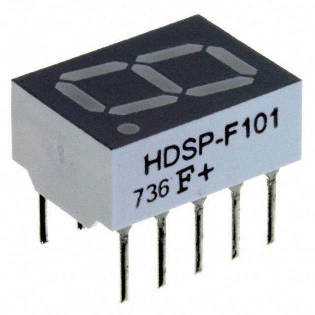
HDSP-740x Series 7.6 mm (0.3 inch) Micro Bright Seven Segment Displays Data Sheet HDSP-740x Series, HDSP-750x Series, HDSP-780x Series, HDSP-A15x Series, HDSP-A40x Series Description Features The 7.6 mm (0.3 inch) LED seven segment displays • Available with colon for clock display are designed for viewing distances up to 3 metres (10 • Compact package feet). These devices use an industry standard size 0.300 x 0.500 inches package and pinout. Both the numeric and ±1. over- Leads on 2.54 mm (0.1 inch) centers flow devices feature a right hand decimal point. All • Choice of colors devices are available as either common anode or AlGaAs Red, High Efficiency Red, Yellow, Green, Orange common cathode. • Excellent appearance Evenly lighted segments These displays are ideal for most applications. Pin for Mitered corners on segments pin equivalent displays are also available in a low Surface color gives optimum contrast current design. The low current displays are ideal for ±50° viewing angle portable applications. For additional information see the Low Current Seven Segment Displays. • Design flexibility Common anode or common cathode Right hand decimal point ±1. overflow character • Categorized for luminous intensity Yellow and Green categorized for color Use of like categories yields a uniform display • High light output • High peak current • Excellent for long digit string multiplexing • Intensity and color selection available See Intensity and Color Selected Displays data sheet • Sunlight viewable AlGaAs Devices Orange AlGaAs[1] HER[1] Yellow[1] Green[1] Package HDSP- HDSP- HDSP- HDSP- HDSP- Description Drawing A401 A151 7501 7401 7801 Common Anode Right A Hand Decimal 7502 7402 7802 Common Anode Right Hand B Decimal, Colon A403 A153 7503 7403 7803 Common Cathode Right C Hand Decimal 7504 7404 7804 Common Cathode Right Hand D Decimal, Colon A157 7507 7407 7807 Common Anode ±1. Overflow E A158 7508 7408 7808 Common Cathode ±1. Overflow F Note: 1. These displays are recommended for high ambient light operation. Please refer to the HDSP-A10X AlGaAs, HDSP-335X HER, HDSP- A80X Yellow, and HDSP-A90X Green data sheet for low current operation.
Part Numbering System 5082 -X X X X-X X X X X HDSP-X X X X-X X X X X Mechanical Options[1] 00: No Mechanical Option Color Bin Options[1,2] 0: No Color Bin Limitation 3: Color Bins 3- and 3+ only (applicable for Yellow devices only) Z: Color Bins 2- and 3+ only (applicable for Yellow devices only) Maximum Intensity Bin[1,2] 0: No Maximum Intensity Bin Limitation Minimum Intensity Bin[1,2] 0: No Minimum Intensity Bin Limitation Device Configuration/Color[1] 1: Common Anode 2: Common Anode 3: Common Cathode 4: Common Cathode Device Specific Configuration[1] Refer to Respective Datasheet Package[1] A: 7.6 mm (0.3 inch) Single Digit Seven Segment Display Notes: 1. For codes not listed in the figure above, please refer to the respective datasheet or contact your nearest Avago representative for details. 2. Bin options refer to shippable bins for a part number. Color and Intensity Bins are typically restricted to 1 bin per tube (exceptions may apply). Please refer to respective datasheet for specific bin limit information. 2
Package Dimensions NOTES: 1. ALL DIMENSIONS IN MILLIMETRES (INCHES). 2. MAXIMUM. 3. ALL UNTOLERANCED DIMENSIONS ARE FOR REFERENCE ONLY. 4. REDUNDANT ANODES. 5. REDUNDANT CATHODES. 6. FOR HDSP-7400/-7800 SERIES PRODUCT ONLY. Internal Circuit Diagram A B C D E F 3
Absolute Maximum Ratings AlGaAs Red HER/Orange Yellow Green HDSP-A150 HDSP-7500/-A40X HDSP-7400 HDSP-7800 Description Series Series Series Series Units Average Power per Segment or DP 96 105 80 105 mW Peak Forward Current per 160[1] 90[3] 60[5] 90[7] mA Segment or DP DC Forward Current per 40[2] 30[4] 20[6] 30[8] mA Segment or DP Operating Temperature Range –20 to +100[9] –40 to +100 °C Storage Temperature Range –55 to +100 °C Reverse Voltage per Segment or DP 3.0 V Wave Soldering Temperature for 3 Seconds (1.59 mm [0.063 in.] 250 °C below Body) Notes: 1. See Figure 1 to establish pulsed conditions. 2. Derate above 46°C at 0.54 mA/°C. 3. See Figure 6 to establish pulsed conditions. 4. Derate above 53°C at 0.45 mA/°C. 5. See Figure 7 to establish pulsed conditions. 6. Derate above 81°C at 0.52 mA/°C. 7. See Figure 8 to establish pulsed conditions. 8. Derate above 39°C at 0.37 mA/°C. 9. For operation below –20°C, contact your local Avago components sales office or an authorized distributor. Electrical/Optical Characteristics at T = 25°C A AlGaAs Red Device Series HDSP- Parameter Symbol Min. Typ. Max. Units Test Conditions Luminous Intensity/Segment[1,2,5] I 6.9 14.0 mcd I = 20 mA V F (Digit Average) 1.8 V I = 20 mA F Forward Voltage/Segment or DP V F 2.0 3.0 V I = 100 mA F A15x Peak Wavelength λ 645 nm PEAK Dominant Wavelength[3] λ 637 nm d Reverse Voltage/Segment or DP[4] V 3.0 15.0 V I = 100 µA R R Temperature Coefficient of ∆V /°C -2 mV/°C F V /Segment or DP F Thermal Resistance LED Junction- Rθ 255 °C/W/Seg J-PIN to-Pin 4
High Efficiency Red Device Series HDSP- Parameter Symbol Min. Typ. Max. Units Test Conditions Luminous Intensity/Segment[1,2,6] 360 980 I = 5 mA F (Digit Average) I µcd V 5390 I = 20 mA F Forward Voltage/Segment or DP V 2.0 2.5 V I = 20 mA F F 750x Peak Wavelength λ 635 nm PEAK Dominant Wavelength[3] λ 626 nm d Reverse Voltage/Segment or DP[4] V 3.0 30 V I = 100 µA R R Temperature Coefficient of ∆V /°C -2 mV/°C F V /Segment or DP F Thermal Resistance LED Junction- Rθ 200 °C/W/Seg J-PIN to-Pin Orange Device Series HDSP- Parameter Symbol Min. Typ. Max. Units Test Conditions Luminous Intensity/Segment[1,2,6] I 0.70 mcd I = 5 mA V F (Digit Average) Forward Voltage/Segment or DP V 2.0 2.5 V I = 20 mA F F A40x Peak Wavelength λ 600 nm PEAK Dominant Wavelength[3] λ 603 nm d Reverse Voltage/Segment or DP[4] V 3.0 30 V I = 100 µA R R Temperature Coefficient of ∆V /°C -2 mV/°C F V /Segment or DP F Thermal Resistance LED Junction- Rθ 200 °C/W/Seg J-PIN to-Pin 5
Yellow Device Series HDSP- Parameter Symbol Min. Typ. Max. Units Test Conditions Luminous Intensity/Segment[1,2,7] 225 480 I = 5 mA F (Digit Average) I µcd V 2740 I = 20 mA F Forward Voltage/Segment or DP V 2.2 2.5 V I = 20 mA F F 740x Peak Wavelength λ 583 nm PEAK Dominant Wavelength[3,9] λ 581.5 586 592.5 nm d Reverse Voltage/Segment or DP[4] V 3.0 50.0 V I = 100 µA R R Temperature Coefficient of ∆V /°C -2 mV/°C F V /Segment or DP F Thermal Resistance LED Junction- Rθ 200 °C/W/Seg J-PIN to-Pin High Performance Green Device Series HDSP- Parameter Symbol Min. Typ. Max. Units Test Conditions Luminous Intensity/Segment[1,2,8] 860 3000 I = 10 mA F (Digit Average) I µcd V 6800 I = 20 mA F Forward Voltage/Segment or DP V 2.1 2.5 V I = 10 mA F F 780x Peak Wavelength λ 566 nm PEAK Dominant Wavelength[3,9] λ 571 577 nm d Reverse Voltage/Segment or DP[4] V 3.0 50.0 V I = 100 µA R R Temperature Coefficient of ∆V /°C -2 mV/°C F V /Segment or DP F Thermal Resistance LED Junction- Rθ 200 °C/W/Seg J-PIN to-Pin Notes: 1. Case temperature of device immediately prior to the intensity measurement is 25°C. 2. The digits are categorized for luminous intensity. The intensity category is designated by a letter on the side of the package. 3. The dominant wavelength, λ , is derived from the CIE chromaticity diagram and is that single wavelength which defines the color of d the device. 4. Typical specification for reference only. Do not exceed absolute maximum ratings. 5. For low current operation the AlGaAs HDSP-A101 series displays are recommended. 6. For low current operation the HER HDSP-7511 series displays are recommended. 7. For low current operation the Yellow HDSP-A801 series displays are recommended. 8. For low current operation the Green HDSP-A901 series displays are recommended. 9. The yellow (HDSP-7400) and Green (HDSP-7800) displays are categorized for dominant wavelength. The category is designated by a number adjacent to the luminous intensity category letter. 6
AlGaAs Red RE T 100 XIMUM OPERATINGNT TO TEMPERATUXIMUM DC CURREN ORTOMEEPPAMGEEXPRRIIOMEAANURTT MIAIRONTEGNUQ RIOUNEFI RT IHEDSICS MAREMA 10 TIO OF AK CURRATED AEE RPD I PEAKFI MAXDC 11 10 10 KHZ13 K0H0z 1 KHz 130000 H0z 100 Hz 10000 DC OPERATION t P – PULSE DURATION – µs Figure 1. Maximum Allowed Peak Current vs. Pulse Duration – AlGaAs Red. 50 A 160 RENT(cid:31) 4450 AlGaAs RED RθJ-A = 770°C/W MENT – m 140 R G 120 I MAX. – MAXIMUM DC CUDCPER SEGMENT – mA 3322115505050 FORWARD CURRENT PER SE 18642000000 AlGaAs RED – 0 F 0 20 30 40 50 60 70 80 90 100 110120 I 0 0.5 1.0 1.5 2.0 2.5 3.0 3.5 4.0 TA – AMBIENT TEMPERATURE – °C VF – FORWARD CURRENT – V Figure 2. Maximum Allowable DC Figure 3. Forward Current vs. Current per Segment as a Function of Forward Voltage. Ambient Temperature. 2.00 Y 1.4 C N Y(cid:31) 1.75 CIE RELATIVE LUMINOUS INTENSIT(NORMALIZED TO 1 AT 20 mA) 111000......520752050505 AlGaAs RED – NORMALIZED RELATIVE EFFIK 011...820 AlGaAs RED A E 0 ηP 0.6 0 5 10 15 20 25 30 35 40 0.5 5.0 50.0 150.0 IF – FORWARD CURRENT PER SEGMENT – mA IPEAK – PEAK FORWARD CURRENT PER SEGMENT – mA Figure 4. Relative Luminous Intensity Figure 5. Relative Efficiency (Luminous vs. DC Forward Current. Intensity per Unit Current) vs. Peak Current. 7
HER, Yellow, Green, Orange RE 100 RE 100 GU GU RATIO OF MAXIMUM OPERATINPEAK CURRENT TO TEMPERATDERATED DC CURRENT 10 ORTOMEEPPAMGEEXPRRIIOMEAANURTT MIAIRONTEGNUQ RIOUNEFI RT IHEDSICS RATIO OF MAXIMUM OPERATINPEAK CURRENT TO TEMPERATDERATED DC CURRENT 10 ORTOMEEPPAMGEEXPRRIIOMEAANURTT MIAIRONTEGNUQ RIOUNEFI RT IHEDSICS I PEAKFI MAXDC 11 10 10 KHZ31 K0H0z 1 KHz 30100 H0z1 0 0 0 Hz 10000 DC OPERATION I PEAKFI MAXDC 11 10 100 KHz13 0K0Hz1 KHz31000 0H10z00 HZ10000 DC OPERATION t P – PULSE DURATION – µs t P – PULSE DURATION – µs Figure 6. Maximum Tolerable Peak Current vs. Figure 7. Maximum Tolerable Peak Pulse Duration – HER, Orange. Current vs. Pulse Duration – Yellow. ATIO OF MAXIMUM OPERATINGEAK CURRENT TO TEMPERATURE ERATED DC CURRENT 11000 ORTOMEEPPAMGEEXPRRIIOMEAANURTT MIAIRONTEGNUQ RIOUNEFI RT IHEDSICS X – MAXIMUM DC CURRENT (cid:31)PER SEGMENT – mA 4122335405050505 GREEN HER, ROθ RJ A- A N G=Y E7E7L0L°CO/WW RPD A M 10 I PEAKFI MAXDC 11 1010 KHZ31 K0H0z 1 KHz 310000 H0z 1 00 Hz 1 0000 DC OPERATION I DC 0520 30 40 50 60 70 80 90 100110120 t P – PULSE DURATION – µs TA – AMBIENT TEMPERATURE – °C Figure 8. Allowable Peak Current vs. Figure 9. Maximum Allowable DC Current per Pulse Duration – Green. Segment as a Function of Ambient Temperature. I – FORWARD CURRENT PER SEGMENT – mAF 1086420000000HER / 1O.0RANGE2.0 GR3E.0EN Y4E.0LLOW5.0 RELATIVE LUMINOUS INTENSITY(cid:31)(NORMALIZED TO 1 AT 5 mA FOR HER AND )t(cid:31)(YELLOW AND TO 1 AT 10 mA FOR GREEN) 1100864220 5 10YELHLO1E5RW /G ORRE2AE0NNGE 25 30 η – RELATIVE EFFICIENCY(cid:31)PEAK(NORMALIZED TO 1 AT 5 mA FOR HER,(cid:31)ORANGE AND YELLOW, AND 10 mA FOR GREEN) 011111......8024860 20YELLOW40 GRH6EE0ERN / ORA8N0GE 100 VF – FORWARD VOLTAGE – V I F – FORWARD CURRENT PER SEGMENT – mA IPEAK – PPEERA KSE FGOMREWNATR –D m CAURRENT(cid:31) Figure 10. Forward Current vs. Figure 11. Relative Luminous Figure 12. Relative Efficiency (Luminous Forward Voltage Characteristics. Intensity vs. DC Forward Current. Intensity per Unit Current) vs. Peak Current. 8
Intensity Bin Limits (mcd) Yellow AlGaAs Red HDSP-A15x HDSP-740x IV Bin Category Min. Max. IV Bin Category Min. Max. M 7.07 13.00 B 0.229 0.387 N 10.60 19.40 C 0.317 0.582 O 15.90 29.20 D 0.476 0.872 P 23.90 43.80 E 0.714 1.311 Q 35.80 65.60 F 1.073 1.967 G 1.609 2.950 HER H 2.413 4.425 HDSP-750x Green IV Bin Category Min. Max. B 0.342 0.630 HDSP-780x C 0.516 0.946 IV Bin Category Min. Max. D 0.774 1.418 H 0.86 1.58 E 1.160 2.127 I 1.29 2.37 F 1.740 3.190 J 1.94 3.55 G 2.610 4.785 K 2.90 5.33 H 3.915 7.177 L 4.37 8.01 Orange HDSP-A40X IV Bin Category Min. Max. A 0.284 0.433 B 0.354 0.541 C 0.443 0.677 D 0.554 0.846 E 0.692 1.057 F 0.856 1.322 G 1.082 1.652 H 1.352 2.066 I 1.692 2.581 J 2.114 3.227 K 2.641 4.034 L 3.300 5.042 M 4.127 6.303 N 5.157 7.878 9
Color Categories Dominant Wavelength (nm) Color Bin Min. Max. Yellow 1 581.50 585.00 3 584.00 587.50 2 586.50 590.00 4 589.00 592.50 Green 2 573.00 577.00 3 570.00 574.00 4 567.00 571.00 5 564.00 568.00 Note: All categories are established for classification of products. Products may not be available in all categories. Please contact your Avago representatives for further clarification/information. Contrast Enhancement For information on contrast enhancement, please see Application Note 1015. Soldering/Cleaning Cleaning agents from the ketone family (acetone, methyl ethyl ketone, etc.) and from the chlorinated hydrocarbon family (methylene chloride, trichloro- ethylene, carbon tetrachloride, etc.) are not recommended for cleaning LED parts. All of these various solvents attack or dissolve the encapsulating epoxies used to form the package of plastic LED parts. For further information on soldering LEDs, please refer to Application Note 1027. For product information and a complete list of distributors, please go to our website: www.avagotech.com Avago, Avago Technologies, and the A logo are trademarks of Avago Technologies Limited in the United States and other countries. Data subject to change. Copyright © 2006 Avago Technologies Limited. All rights reserved. Obsoletes 5988-0382EN 5988-4434EN June 10, 2006