ICGOO在线商城 > 电感器,线圈,扼流圈 > 固定值电感器 > HCM0703-1R5-R
 Datasheet下载
- 型号: HCM0703-1R5-R
- 制造商: Bussmann/Cooper
- 库位|库存: xxxx|xxxx
- 要求:
| 数量阶梯 | 香港交货 | 国内含税 |
| +xxxx | $xxxx | ¥xxxx |
查看当月历史价格
查看今年历史价格
HCM0703-1R5-R产品简介:
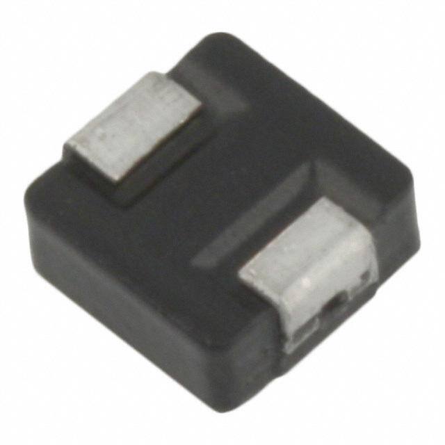
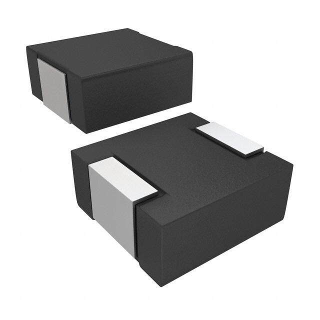
ICGOO电子元器件商城为您提供HCM0703-1R5-R由Bussmann/Cooper设计生产,在icgoo商城现货销售,并且可以通过原厂、代理商等渠道进行代购。 HCM0703-1R5-R价格参考¥2.00-¥2.50。Bussmann/CooperHCM0703-1R5-R封装/规格:固定值电感器, 1.5µH 屏蔽 绕线 电感器 9A 15 毫欧最大 非标准 。您可以下载HCM0703-1R5-R参考资料、Datasheet数据手册功能说明书,资料中有HCM0703-1R5-R 详细功能的应用电路图电压和使用方法及教程。
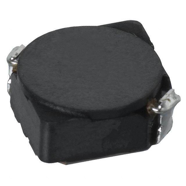
Eaton - Electronics Division的固定值电感器型号HCM0703-1R5-R,是一款小型片式电感器,适用于多种电子电路中的滤波、匹配和储能等场景。以下是其主要应用场景:

 1. 电源滤波
   - HCM0703-1R5-R可用于直流-直流转换器(DC-DC Converter)或开关电源(SMPS)中的输入/输出滤波电路,抑制高频噪声,确保电源信号的纯净。
   - 在电源管理模块中,该电感器能够减少电磁干扰(EMI),提高系统的稳定性。

 2. 射频(RF)电路
   - 在射频前端电路中,这款电感器可作为匹配网络的一部分,用于调整阻抗以实现最佳功率传输。
   - 它也可用于滤除射频信号中的不需要的频率成分,保持信号的完整性。

 3. 信号滤波
   - 在音频、视频或其他模拟信号处理电路中,HCM0703-1R5-R可以与电容器配合组成低通、高通或带通滤波器,去除特定频率范围内的干扰信号。
   - 对于数字电路,它可用于时钟信号或数据线的去耦滤波,降低噪声对信号的影响。

 4. 无线通信设备
   - 该电感器适用于蓝牙、Wi-Fi、Zigbee等短距离无线通信模块中的LC谐振电路,提供稳定的谐振频率。
   - 在天线匹配电路中,它有助于优化天线性能,提高信号发射和接收效率。

 5. 汽车电子
   - 在车载电子系统中,如信息娱乐系统、传感器模块或控制单元,HCM0703-1R5-R可用于电源滤波和信号调理,确保系统在复杂电磁环境下正常运行。

 6. 消费电子产品
   - 在智能手机、平板电脑、笔记本电脑等便携式设备中,这款电感器常用于电源管理芯片周围的滤波电路,支持高效能和低功耗设计。

 特点总结:
   - 小型化设计(适合高密度组装)
   - 高可靠性(符合工业标准)
   - 稳定的电感值(1.5μH)
   - 良好的直流电阻特性

综上所述,HCM0703-1R5-R适用于需要高性能、小体积电感器的各种电子设备,尤其在电源管理和射频领域表现优异。
| 参数 | 数值 |
| 产品目录 | |
| DC电阻(DCR) | 15 毫欧最大 |
| 描述 | INDUCTOR HIGH CURRENT 1.5UH SMD固定电感器 1.5uH 18.0A SMD HIGH CURRENT |
| 产品分类 | |
| 品牌 | Eaton Bussmann |
| 产品手册 | |
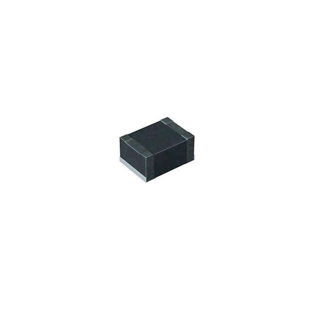
| 产品图片 |
|
| rohs | 符合RoHS无铅 / 符合限制有害物质指令(RoHS)规范要求 |
| 产品系列 | 固定电感器,Bussmann / Eaton HCM0703-1R5-RHCM0703 |
| 数据手册 | |
| 产品型号 | HCM0703-1R5-R |
| 不同频率时的Q值 | - |
| 产品 | Inductors |
| 产品目录绘图 |
|
| 产品目录页面 | |
| 产品种类 | 固定电感器 |
| 供应商器件封装 | - |
| 其它名称 | 513-1702-2 |
| 包装 | 带卷 (TR) |
| 单位重量 | 453.592 mg |
| 商标 | Bussmann / Eaton |
| 外壳宽度 | 6.8 mm |
| 外壳长度 | 7.1 mm |
| 外壳高度 | 3 mm |
| 大小/尺寸 | 0.280" 长 x 0.268" 宽 (7.10mm x 6.80mm) |
| 安装类型 | 表面贴装 |
| 容差 | ±20% |
| 封装 | Reel |
| 封装/外壳 | 非标准 |
| 屏蔽 | 屏蔽 |
| 工作温度 | -55°C ~ 125°C |
| 工作温度范围 | - 55 C to + 125 C |
| 工厂包装数量 | 1500 |
| 最大直流电流 | 18 A |
| 最大直流电阻 | 15 mOhms |
| 材料-磁芯 | 铁粉 |
| 标准包装 | 1,500 |
| 测试频率 | 100 kHz |
| 特色产品 | http://www.digikey.com/cn/zh/ph/CooperBussmann/HCM0703_series.html |
| 电感 | 1.5µH |
| 电流-饱和值 | 18A |
| 端接类型 | SMD/SMT |
| 类型 | 绕线 |
| 系列 | HCM0703 |
| 芯体材料 | Powdered Iron |
| 频率-测试 | 100kHz |
| 频率-自谐振 | - |
| 额定电流 | 9A |
| 高度-安装(最大值) | 0.118"(3.00mm) |


- 商务部:美国ITC正式对集成电路等产品启动337调查
- 曝三星4nm工艺存在良率问题 高通将骁龙8 Gen1或转产台积电
- 太阳诱电将投资9.5亿元在常州建新厂生产MLCC 预计2023年完工
- 英特尔发布欧洲新工厂建设计划 深化IDM 2.0 战略
- 台积电先进制程称霸业界 有大客户加持明年业绩稳了
- 达到5530亿美元!SIA预计今年全球半导体销售额将创下新高
- 英特尔拟将自动驾驶子公司Mobileye上市 估值或超500亿美元
- 三星加码芯片和SET,合并消费电子和移动部门,撤换高东真等 CEO
- 三星电子宣布重大人事变动 还合并消费电子和移动部门
- 海关总署:前11个月进口集成电路产品价值2.52万亿元 增长14.8%


PDF Datasheet 数据手册内容提取
Effective March 2016 Technical Data 4085 Supersedes December 2014 HCM0703 High current power inductors Applications • Voltage Regulator Module (VRM) • Multi-phase regulators • Point-of-loadmodules • Desktop and server VRMs and EVRDs • Base station equipment • Laptop and notebook regulators • Battery power systems • Graphics cards • Data networking and storage systems Environmental Data Product features • Storage temperature range (Component): -55 °C to +125 °C • High current carrying capacity • Operating temperature range: -55 °C to +125 °C • Low core losses (ambient plus self-temperature rise) • Magnetically shielded, low EMI • Solder reflow temperature: J-STD-020 compliant (Latest revision) • Frequency range up to 5 MHz • Inductance range from 0.15 μH to 33 μH Pb HHALOFGEN • Current range from 1.8 A to 52 A FREE • 7.4 mm x 6.8 mm footprint surface mount package in a 3.0 mm height • Iron powder core material
Technical Data 4085 HCM0703 Effective March 2016 High current power inductors Product Specifications OCL1 FLL2 (μH) I 3 I 4 DCR (mΩ) DCR (mΩ) rms sat Part Number6 (μH) ±20% minimum (A ) (A ) typical @ +20 °C maximum @ +20 °C K-factor5 HCM0703-R15-R 0.15 0.09 26 52 1.9 2.5 1044 HCM0703-R22-R 0.22 0.13 23 40 2.5 2.8 986 HCM0703-R47-R 0.47 0.28 17.5 26 4.0 4.2 580 HCM0703-R68-R 0.68 0.41 15.5 25 5.0 5.5 455 HCM0703-R82-R 0.82 0.49 13 24 6.7 8.0 439 HCM0703- 1R0-R 1.0 0.60 11 22 9.0 10 374 HCM0703- 1R5-R 1.5 0.90 9.0 18 14 15 366 HCM0703- 2R2-R 2.2 1.3 8.0 14 18 20 281 HCM0703- 3R3-R 3.3 2.0 6.0 13.5 28 30 252 HCM0703- 4R7-R 4.7 2.8 5.5 10 37 40 210 HCM0703- 6R8-R 6.8 4.1 4.5 8.0 54 60 151 HCM0703- 8R2-R 8.2 4.9 4.0 7.5 64 68 142 HCM0703- 100-R 10 6.0 3.2 7.0 71 78 132 HCM0703- 150-R 14.9±15% 10.1 2.2 5.0 113 127 105 HCM0703- 220-R 22 14.1 2.3 3.0 135 149 83 HCM0703- 330-R 33 19.8 1.8 2.2 220 242 76 1. Open Circuit Inductance (OCL) Test Parameters: 100 kHz, 0.25 Vrms, 0.0 Adc, +25°C. 4. Isat: Peak current for approximately 20% rolloff at +25 °C. 2. Full Load Inductance (FLL) Test Parameters: 100 kHz, 0.25 Vrms, Isat, @ +25 °C. 5. K-factor: Used to determine Bp-p for core loss (see graph). Bp-p = K * L * ΔI. Bp-p: (Gauss), K: (K-factor from table), L: 3. Irms: DC current for an approximate temperature rise of 40 °C without core loss. Derating is necessary for AC currents. (Inductance in μH), ΔI (Peak to peak ripple current in Amps). PCB layout, trace thickness and width, air-flow, and proximity of other heat generating components will affect the 6. Part Number Definition: HCM0703-xxx-R temperature rise. It is recommended that the temperature of the part not exceed +125 °C under worst case operating HCM0703 = Product code and size conditions verified in the end application. -xxx= Inductance value in μH, R = decimal point, if no R is present then last character equals number of zeros. “-R” suffix = RoHS compliant Dimensions (mm) Part marking: XXX=Inductance value in uH, R= decimal point. If no R is present then last character equals number of zeros. wly=date code, R=revision level All soldering surfaces to be coplanar within 0.10 millimeters Tolerances are ±0.3 millimeters unless stated otherwise Color: Grey 2 www.eaton.com/electronics
HCM0703 Technical Data 4085 High current power inductors Effective March 2016 Packaging information (mm) Supplied in tape and reel packaging, 1500 parts per 13” diameter reel. Temperature rise vs. total loss 50.0 40.0 C) ° e ( s Ri 30.0 e r u t a r e p m 20.0 e T 10.0 0.0 0.0 0.2 0.4 0.6 0.8 1.0 1.2 Total Loss (W) www.eaton.com/electronics 3
Technical Data 4085 HCM0703 Effective March 2016 High current power inductors Core loss vs. Bp-p 10000 1 MHz 500 kHz 1000 300 kHz 200 kHz 100 kHz W) 100 m s ( s o L e r Co 10 1 0.1 100 1000 10000 B (Gauss) p-p Inductance characteristics HCM0703-R15-R HCM0703-R22-R 110% 110% 100% 100% 90% 90% L L C 80% C80% O O % of 70% % of 70% 60% 60% 50% 50% 40% 40% 0 10 20 30 40 50 60 70 0 10 20 30 40 50 60 70 I (A) DC I (A) DC 4 www.eaton.com/electronics
HCM0703 Technical Data 4085 High current power inductors Effective March 2016 Inductance characteristics HCM0703-R47-R HCM0703-R68-R 110% 110% 100% 100% 90% 90% L L C80% C80% O O f f o o % 70% % 70% 60% 60% 50% 50% 40% 40% 0 5 10 15 20 25 30 35 40 45 50 0 5 10 15 20 25 30 35 40 45 I (A) I (A) DC DC HCM0703-R82-R HCM0703-1R0-R 110% 110% 100% 100% 90% 90% L OC80% CL 80% O of f % 70% % o 70% 60% 60% 50% 50% 40% 40% 0 5 10 15 20 25 30 35 40 45 0 5 10 15 20 25 30 35 40 IDC(A) IDC(A) HCM0703-1R5-R HCM0703-2R2-R 110% 110% 100% 100% 90% 90% L L C80% C80% O O of of % 70% % 70% 60% 60% 50% 50% 40% 40% 0 5 10 15 20 25 30 35 0 5 10 15 20 25 30 I (A) I (A) DC DC www.eaton.com/electronics 5
Technical Data 4085 HCM0703 Effective March 2016 High current power inductors Inductance characteristics HCM0703-3R3-R HCM0703-4R7-R 110% 110% 100% 100% 90% 90% L L C80% C80% O O % of 70% % of 70% 60% 60% 50% 50% 40% 40% 0 2 4 6 8 10 12 14 16 18 20 0 2 4 6 8 10 12 14 16 18 20 IDC(A) IDC(A) HCM0703-6R8-R HCM0703-8R2-R 110% 110% 100% 100% 90% 90% L L C80% C80% O O % of 70% % of 70% 60% 60% 50% 50% 40% 40% 0 2 4 6 8 10 12 14 0 2 4 6 8 10 12 14 IDC(A) IDC(A) HCM0703-100-R HCM0703-150-R 110% 110% 100% 100% 90% 90% L L C80% C 80% O O % of 70% % of 70% 60% 60% 50% 50% 40% 40% 0 2 4 68 1 0 12 14 0 1 2 3 4 5 6 7 8 9 10 I (A) DC I (A) DC 6 www.eaton.com/electronics
HCM0703 Technical Data 4085 High current power inductors Effective March 2016 Inductance characteristics HCM0703-220-R HCM0703-330-R 110% 110% 100% 100% 90% 90% L L C80% C80% O O f f o o % 70% % 70% 60% 60% 50% 50% 40% 40% 0 1 2 3 4 5 6 0 1 2 3 4 5 6 I (A) I (A) DC DC www.eaton.com/electronics 7
Technical Data 4085 HCM0703 Effective March 2016 High current power inductors Solder reflow profile TP Table 1 - Standard SnPb Solder (Tc) TC -5°C Max. Ramp Up Rate = 3°C/s tP Volume Volume Package mm3 mm3 Max. Ramp Down Rate = 6°C/s Thickness <350 ≥350 TL <2.5 mm) 235 °C 220 °C Preheat t ≥2.5 mm 220 °C 220 °C A e Tsmax ur Table 2 - Lead (Pb) Free Solder (Tc) at er Volume Volume Volume Temp Tsmin ts PThacickkangees s <m3m503 3m5m03 - 2000 >m2m030 0 <1.6 mm 260 °C 260 °C 260 °C 1.6 – 2.5 mm 260 °C 250 °C 245 °C >2.5 mm 250 °C 245 °C 245 °C 25°C Time 25°C to Peak Time Reference JDEC J-STD-020 Profile Feature Standard SnPb Solder Lead (Pb) Free Solder Preheat and Soak • Temperature min. (Tsmin) 100 °C 150 °C • Temperature max. (Tsmax) 150 °C 200 °C • Time (Tsmin to Tsmax) (ts) 60-120 seconds 60-120 seconds Average ramp up rate Tsmax to Tp 3 °C/ second Max. 3 °C/ second Max. Liquidous temperature (Tl) 183°C 217°C Time at liquidous (tL) 60-150 seconds 60-150 seconds Peak package body temperature (TP)* Table 1 Table 2 Time (tp)** within 5 °C of the specified classification temperature (Tc) 20 seconds** 30 seconds** Average ramp-down rate (Tp to Tsmax) 6 °C/ second Max. 6 °C/ second Max. Time 25 °C to Peak Temperature 6 Minutes Max. 8 Minutes Max. * Tolerance for peak profile temperature (Tp) is defined as a supplier minimum and a user maximum. ** Tolerance for time at peak profile temperature (tp) is defined as a supplier minimum and a user maximum. Life Support Policy: Eaton does not authorize the use of any of its products for use in life support devices or systems without the express written approval of an officer of the Company. Life support systems are devices which support or sustain life, and whose failure to perform, when properly used in accordance with instructions for use provided in the labeling, can be reasonably expected to result in significant injury to the user. Eaton reserves the right, without notice, to change design or construction of any products and to discontinue or limit distribution of any products. Eaton also reserves the right to change or update, without notice, any technical information contained in this bulletin. Eaton Electronics Division 1000 Eaton Boulevard Cleveland, OH 44122 United States www.eaton.com/electronics © 2016 Eaton All Rights Reserved Eaton is a registered trademark. Printed in USA Publication No. 4085 BU-MC16036 All other trademarks are property March 2016 of their respective owners.