ICGOO在线商城 > 传感器,变送器 > 光学传感器 - 测距 > GP2Y3A001K0F
 Datasheet下载
- 型号: GP2Y3A001K0F
- 制造商: Sharp Microelectronics
- 库位|库存: xxxx|xxxx
- 要求:
| 数量阶梯 | 香港交货 | 国内含税 |
| +xxxx | $xxxx | ¥xxxx |
查看当月历史价格
查看今年历史价格
GP2Y3A001K0F产品简介:
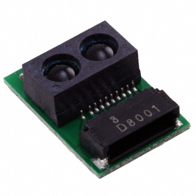
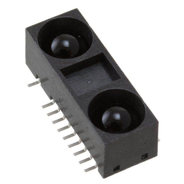
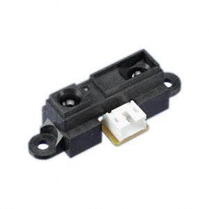
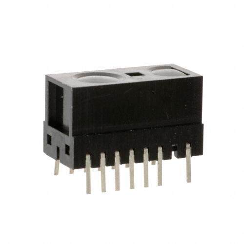
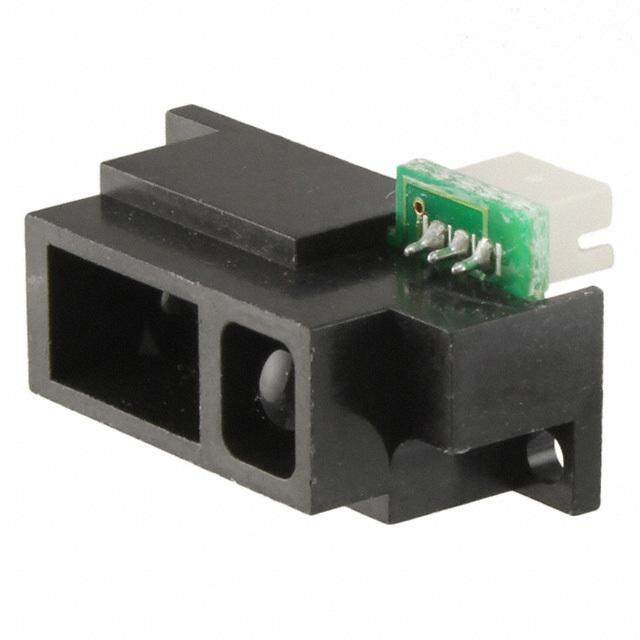
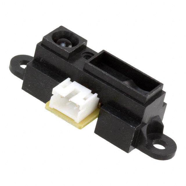
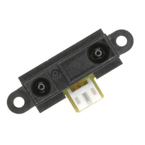
ICGOO电子元器件商城为您提供GP2Y3A001K0F由Sharp Microelectronics设计生产,在icgoo商城现货销售,并且可以通过原厂、代理商等渠道进行代购。 GP2Y3A001K0F价格参考。Sharp MicroelectronicsGP2Y3A001K0F封装/规格:光学传感器 - 测距, Optical Sensor 1.57" ~ 11.81" (4 ~ 30cm) Analog Output。您可以下载GP2Y3A001K0F参考资料、Datasheet数据手册功能说明书,资料中有GP2Y3A001K0F 详细功能的应用电路图电压和使用方法及教程。
Sharp Microelectronics的GP2Y3A001K0F是一款光学传感器,主要用于测距应用。这款传感器采用红外线技术,能够精确测量物体与传感器之间的距离,具有响应速度快、精度高、可靠性强等特点。以下是该型号传感器的一些典型应用场景:

 1. 机器人导航
   GP2Y3A001K0F广泛应用于机器人领域,尤其是在自主导航和避障系统中。通过安装在机器人的不同位置,传感器可以实时检测周围环境中的障碍物,并根据距离信息调整机器人的行进方向,确保其安全、高效地完成任务。

 2. 智能家居设备
   在智能家居产品中,如智能扫地机器人、智能家电等,GP2Y3A001K0F可以帮助设备感知周围环境,避免碰撞。例如,扫地机器人可以通过该传感器识别家具、墙壁等障碍物,优化清洁路径,提高工作效率。

 3. 工业自动化
   在工业生产线上,GP2Y3A001K0F可以用于检测物体的位置和距离,帮助实现自动化装配、物料搬运等操作。它还可以用于监控生产线上的物品间距,确保生产过程的顺利进行,减少人为干预。

 4. 无人机避障
   无人机在飞行过程中需要实时感知周围环境,以避免与建筑物、树木或其他障碍物发生碰撞。GP2Y3A001K0F可以安装在无人机上,提供精确的距离测量数据,帮助无人机实现自动避障功能,提升飞行安全性。

 5. 安防监控
   在安防领域,GP2Y3A001K0F可以用于入侵检测系统。通过设置传感器在关键区域,当有物体进入设定范围内时,传感器会触发警报,及时通知监控中心或安保人员采取措施。

 6. 医疗设备
   在一些医疗设备中,如手术机器人或康复辅助设备,GP2Y3A001K0F可以用于精确控制机械臂的动作,确保其与患者保持安全距离,避免意外伤害。

总的来说,GP2Y3A001K0F凭借其出色的测距性能,适用于多种需要精确距离测量的应用场景,特别是在自动化、智能化设备中发挥着重要作用。
| 参数 | 数值 |
| 产品目录 | |
| 描述 | SENSOR DIST MEAS 4-30CM ANLG |
| 产品分类 | |
| 品牌 | Sharp Microelectronics |
| 数据手册 | http://www.sharpsma.com/webfm_send/1485http://www.sharpsma.com/webfm_send/1176 |
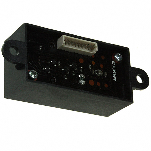
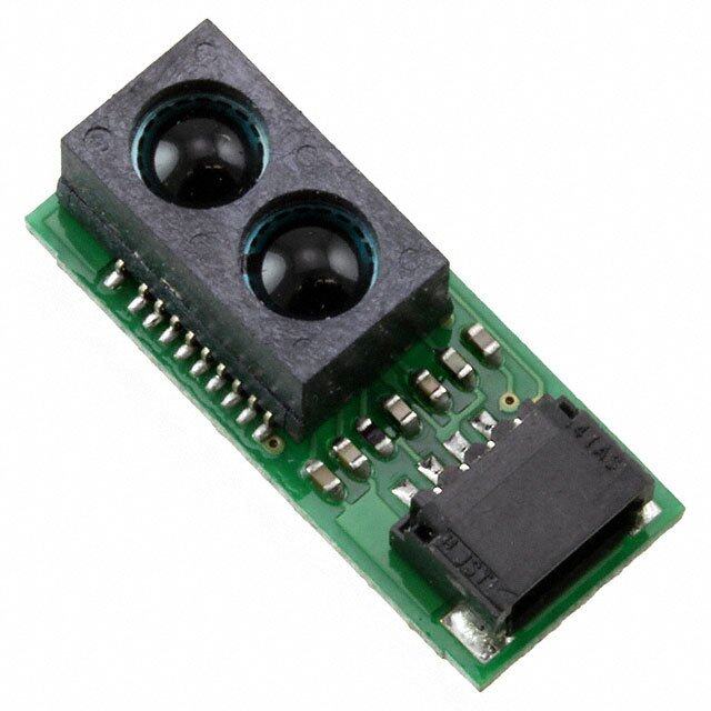
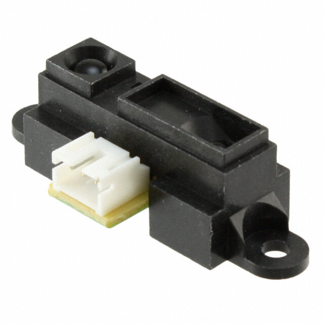
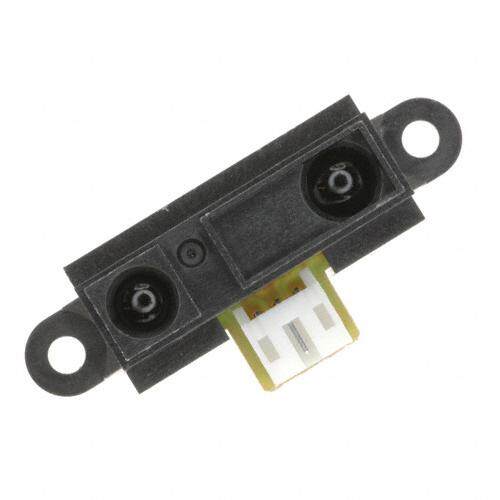
| 产品图片 |
|
| 产品型号 | GP2Y3A001K0F |
| rohs | 无铅 / 符合限制有害物质指令(RoHS)规范要求 |
| 产品系列 | - |
| 不同距离时的电压-输出差异(典型值) | 1.6V @ 4 ~ 10cm |
| 不同距离时的电压-输出(典型值) | 2.85V @ 4cm |
| 产品目录页面 | |
| 其它名称 | 425-2498 |
| 感应距离 | 4 ~ 30cm |
| 标准包装 | 100 |
| 电压-电源 | 4.5 V ~ 5.5 V |
| 电流-电源 | 50mA |
| 输出类型 | 模拟 |


- 商务部:美国ITC正式对集成电路等产品启动337调查
- 曝三星4nm工艺存在良率问题 高通将骁龙8 Gen1或转产台积电
- 太阳诱电将投资9.5亿元在常州建新厂生产MLCC 预计2023年完工
- 英特尔发布欧洲新工厂建设计划 深化IDM 2.0 战略
- 台积电先进制程称霸业界 有大客户加持明年业绩稳了
- 达到5530亿美元!SIA预计今年全球半导体销售额将创下新高
- 英特尔拟将自动驾驶子公司Mobileye上市 估值或超500亿美元
- 三星加码芯片和SET,合并消费电子和移动部门,撤换高东真等 CEO
- 三星电子宣布重大人事变动 还合并消费电子和移动部门
- 海关总署:前11个月进口集成电路产品价值2.52万亿元 增长14.8%
PDF Datasheet 数据手册内容提取
GP2Y3A001K0F GP2Y3A001K0F Wide angle Distance Measuring Sensor Unit Measuring distance: 4 to 30 cm 5 Analog outputs type ■Description ■Agency approvals/Compliance GP2Y3A001K0F is a distance measuring sensor unit, 1. Compliant with RoHS directive (2002/95/EC) composed of an integrated combination of PSD (position sensitive detector) , 5-IREDs (infrared emitting diode) and signal processing circuit. The variety of the reflectivity of the object, the ■Applications environmental temperature and the operating duration are not influenced easily to the distance detection 1. Robot cleaner because of adopting the triangulation method. 2. Vending machine This device uses 5 infrared beams for wide range 3. ATM/CD (field of view) detection. This device outputs the 5 4. Amusement equipment voltages corresponding to the each distance detection. (Robot, Arcade game machine) ■Features 1. Short range type Measuring distance range : 4 to 30 cm 2. 5 Analog outputs type 3. Package size : 40×20×15 mm 4. Consumption current : Typ. 30 mA 5. Supply voltage : 4.5 to 5.5 V 6. Detection angle : 25° Notice The content of data sheet is subject to change without prior notice. In the absence of confirmation by device specification sheets, SHARP takes no responsibility for any defects that may occur in equipment using any SHARP devices shown in catalogs, data books, etc. Contact SHARP in order to obtain the latest device specification sheets before using any SHARP device. Sheet No.: E4-A01201EN 1 Date Dec.01.2006 ©SHARP Corporation 44 2Y3A001 F 44 2Y3A001 F
GP2Y3A001K0F ■Block diagram ⑦GND ⑧V CC PSD Signal processing ⑨V circuit Voltage regulator in ⑥V O Oscillation circuit LED1 LED drive circuit Output circuit 5 LEDs ①LED1 5 pcs of transistor LED5 ⑤LED5 ■Outline Dimensions (Unit : mm) 55 Terminal Symbol 47.5 40 ① Signal inputs for selecting LED1 LED1 ② Signal inputs for selecting LED2 LED2 ③ Signal inputs for selecting LED3 LED3 9.4 ④ Signal inputs for selecting LED4 LED4 ⑤ Signal inputs for selecting LED5 LED5 0 φ7.52 ⑥ Output terminal voltage VO φ ⑦ Ground GND 3. 2 ⑧ Supply voltage V CC ⑨ Input voltage V IR Emitter IR Detector in 4444 5 22YY33AA000011 FF 1 ) 5 1. ( Stamp 13 (15.4) 5 1. (2.2) Pin number ①→⑨ Year(2004 : 4) Stamp (Example) Month(1 to 9, X, Y, Z) 4444 22YY33AA000011 FF Model name Note 1. Unspecified tolerances shall be ± 0.3 mm. Note 2. The connector is made by Molex and its part number is 53047-0910. Note 3. The dimensions in parenthesis are shown for reference. Product mass : approx. 7.5g Sheet No.: E4-A01201EN 2
44 2Y3A001 F 44 2Y3A001 F GP2Y3A001K0F ■Absolute Maximum Ratings (Ta=25℃,VCC=5V) Parameter Symbol Rating Unit Supply voltage V -0.3 to +7 V CC Output terminal voltage V -0.3 to V +0.3 V O CC V H/L Input voltage in -0.3 to V +0.3 V CC LED H/L Operating temperature T -10 to +60 ℃ opr Storage temperature T -40 to +70 ℃ stg ■Electro-optical Characteristics (Ta=25℃,VCC=5V) Parameter Symbol Conditions MIN. TYP. MAX. Unit Average supply current I ― 30 50 mA CC Distance measuring range ΔL (Note 1) 4 ― ― cm Output voltage V L = 4 cm (Note 1) 2.55 2.85 3.15 V O Output voltage difference between Output voltage differential ΔV 1.3 1.6 1.9 V O L=4cm and L=10cm (Note 1) Input voltage for operating distance V 4.5 ― ― V inH measuring sensor Input voltage for turning off distance Input voltage V ― ― 0.3 V inL measuring sensor LED H Input voltage for turning LED on 4.5 ― ― V LED L Input voltage for turning LED off ― ― 0.5 V * L : Distance to reflective object Note 1 : Using reflective object : White paper (Made by Kodak Co., Ltd. gray cards R-27·white face, reflectance; 90%) ■Recommended operating conditions Parameter Symbol Conditions Rating Unit Supply voltage V 4.5 to 5.5 V CC Sheet No.: E4-A01201EN 3
44 2Y3A001 F 44 2Y3A001 F GP2Y3A001K0F Fig. 1 Timing chart Distance measuring operation MIN 5 ms MIN 5 ms Start signal V Reset signal in Distance measuring operation Start signal LED1 (LED1 ON) LED2 (LED2 ON) LED3 (LED3 ON) LED4 LED5 16.5 ms ± 3.7 ms 16.5 ms ± 3.7 ms 16.5 ms ± 3.7 ms 5th measuring nthmeasuring Distance measuring 1st measuring 2ndmeasuring 3rd measuring 4th measuring … operation Unstable outpu t VO (output) Unstable output 1st output 2ndoutput Unstable output 4th output … (Output for LED1) (Output for LED2) MAX 5.0 ms MAX 5.0 ms MAX 5.0 m s Note 1 : Output voltage shall be unstable without Vin H.. Note 2 : Please don’t turn on more than two LEDs at the same time. Sheet No.: E4-A01201EN 4
44 2Y3A001 F 44 2Y3A001 F GP2Y3A001K0F Fig. 2 Example of distance measuring characteristics (output) 3 2.5 LED1 ) V ( LED2 e 2 g LED3 a t l o LED4 v ut 1.5 LED5 p t u O 1 0.5 0 0 5 10 15 20 25 30 Distance (cm) Sheet No.: E4-A01201EN 5
44 2Y3A001 F 44 2Y3A001 F GP2Y3A001K0F ■ Notes ● Advice for the optics • The lens of this device needs to be kept clean. There are cases that dust, water or oil and so on deteriorate the characteristics of this device. Please consider in actual application. • Please don’t do washing. Washing may deteriorate the characteristics of optical system and so on. Please confirm resistance to chemicals under the actual usage since this product has not been designed against washing. ● Advice for the characteristics • In case that an optical filter is set in front of the emitter and detector portion, the optical filter which has the most efficient transmittance at the emitting wavelength range of LED for this product (λ = 870 ± 70nm), shall be recommended to use. Both faces of the filter should be mirror polishing. Also, as there are cases that the characteristics may not be satisfied according to the distance between the protection cover and this product or the thickness of the protection cover, please use this product after confirming the operation sufficiently in actual application. • In case that there is an object near to emitter side of the sensor between sensor and a detecting object, please use this device after confirming sufficiently that the characteristics of this sensor do not change by the object. • When the detector is exposed to the direct light from the sun, tungsten lamp and so on, there are cases that it can not measure the distance exactly. Please consider the design that the detector is not exposed to the direct light from such light source. • Distance to a mirror reflector can not be sometimes measured exactly. In case of changing the mounting angle of this product, it may measure the distance exactly. • In case that reflective object has boundary line which material or color etc. are excessively different, in order to decrease deviation of measuring distance, it shall be recommended to set the sensor that the direction of boundary line and the line between emitter center and detector center are in parallel. (Incorrect) (Correct) • In order to decrease deviation of measuring distance by moving direction of the reflective object, it shall be recommended to set the sensor that the moving direction of the object and the line between emitter center and detector center are vertical. (Incorrect) (Correct) (Moving direction) (Moving direction) ● Advice for the power supply • In order to stabilize power supply line, we recommend to insert a by-pass capacitor of 10μF or more between Vcc and GND near this product. ● Notes on handling • There are some possibilities that the internal components in the sensor may be exposed to the excessive mechanical stress. Please be careful not to cause any excessive pressure on the sensor package and also on the PCB while assembling this product. Sheet No.: E4-A01201EN 6
44 2Y3A001 F 44 2Y3A001 F GP2Y3A001K0F ● Presence of ODC etc. This product shall not contain the following materials. And they are not used in the production process for this product. Regulation substances : CFCs, Halon, Carbon tetrachloride, 1.1.1-Trichloroethane (Methylchloroform) Specific brominated flame retardants such as the PBB and PBDE are not used in this product at all. This product shall not contain the following materials banned in the RoHS Directive (2002/95/EC). • Lead, Mercury, Cadmium, Hexavalent chromium, Polybrominated biphenyls (PBB), Polybrominated diphenyl ethers (PBDE). Sheet No.: E4-A01201EN 7
44 2Y3A001 F 44 2Y3A001 F GP2Y3A001K0F ■Package specification Package method MAX.50 pieces per tray MAX 500 pieces per case Arranges in 10 stages of trays containing products into the outer case. Put pads between trays. Closes the lid of case and seals with kraft tape. Pad Package composition Product Tray Packing case Tray section Product Sheet No.: E4-A01201EN 8
44 2Y3A001 F 44 2Y3A001 F GP2Y3A001K0F ■Important Notices · The circuit application examples in this publication are with equipment that requires higher reliability such as: provided to explain representative applications of --- Transportation control and safety equipment (i.e., SHARP devices and are not intended to guarantee any circuit aircraft, trains, automobiles, etc.) design or license any intellectual property rights. SHARP --- Traffic signals takes no responsibility for any problems related to any --- Gas leakage sensor breakers intellectual property right of a third party resulting from the use --- Alarm equipment of SHARP's devices. --- Various safety devices, etc. (iii) SHARP devices shall not be used for or in · Contact SHARP in order to obtain the latest device specifi- connection with equipment that requires an extremely high cation sheets before using any SHARP device. SHARP level of reliability and safety such as: reserves the right to make changes in the specifications, --- Space applications characteristics, data, materials, structure, and other --- Telecommunication equipment [trunk lines] contents described herein at any time without notice in --- Nuclear power control equipment order to improve design or reliability. Manufacturing --- Medical and other life support equipment (e.g., locations are also subject to change without notice. scuba). · Observe the following points when using any devices in this · If the SHARP devices listed in this publication fall publication. SHARP takes no responsibility for damage within the scope of strategic products described in the caused by improper use of the devices which does not meet the Foreign Exchange and Foreign Trade Law of Japan, it is conditions and absolute maximum ratings to be used specified necessary to obtain approval to export such SHARP devices. in the relevant specification sheet nor meet the following condi- tions: · This publication is the proprietary product of SHARP and (i) The devices in this publication are designed for use in is copyrighted, with all rights reserved. Under the copy- general electronic equipment designs such as: right laws, no part of this publication may be repro- --- Personal computers duced or transmitted in any form or by any means, --- Office automation equipment electronic or mechanical, for any purpose, in whole or in --- Telecommunication equipment [terminal] part, without the express written permission of SHARP. --- Test and measurement equipment Express written permission is also required before any use --- Industrial control of this publication may be made by a third party. --- Audio visual equipment --- Consumer electronics · Contact and consult with a SHARP representative if there (ii) Measures such as fail-safe function and redundant design are any questions about the contents of this publication. should be taken to ensure reliability and safety when SHARP devices are used for or in connection Sheet No.: E4-A01201EN 9