ICGOO在线商城 > GMA.2B.045.DN

 Datasheet下载
- 型号: GMA.2B.045.DN
- 制造商: LEMO
- 库位|库存: xxxx|xxxx
- 要求:
| 数量阶梯 | 香港交货 | 国内含税 |
| +xxxx | $xxxx | ¥xxxx |
查看当月历史价格
查看今年历史价格
GMA.2B.045.DN产品简介:
ICGOO电子元器件商城为您提供GMA.2B.045.DN由LEMO设计生产,在icgoo商城现货销售,并且可以通过原厂、代理商等渠道进行代购。 提供GMA.2B.045.DN价格参考¥23.03-¥28.90以及LEMOGMA.2B.045.DN封装/规格参数等产品信息。 你可以下载GMA.2B.045.DN参考资料、Datasheet数据手册功能说明书, 资料中有GMA.2B.045.DN详细功能的应用电路图电压和使用方法及教程。
| 参数 | 数值 |
| 产品目录 | |
| 描述 | BEND RELIEF 4.5MM BLACK环形推拉式连接器 BEND RELIEF |
| 产品分类 | |
| 品牌 | LEMO |
| 产品手册 | |
| 产品图片 | |
| rohs | 符合RoHS无铅 / 符合限制有害物质指令(RoHS)规范要求 |
| 产品系列 | 环形推拉式连接器,LEMO GMA.2B.045.DN2B |
| 数据手册 | |
| 产品型号 | GMA.2B.045.DN |
| 产品种类 | 环形推拉式连接器 |
| 商标 | LEMO |
| 商标名 | B |
| 外壳尺寸-插件 | - |
| 材料 | 聚氨酯弹性体 |
| 标准包装 | 1 |
| 特性 | 防尘 |
| 系列 | 2B |
| 配件类型 | 应力消除 |
| 配套使用产品/相关产品 | 2B, 2S 系列连接器 |
| 颜色 | 黑 |


- 商务部:美国ITC正式对集成电路等产品启动337调查
- 曝三星4nm工艺存在良率问题 高通将骁龙8 Gen1或转产台积电
- 太阳诱电将投资9.5亿元在常州建新厂生产MLCC 预计2023年完工
- 英特尔发布欧洲新工厂建设计划 深化IDM 2.0 战略
- 台积电先进制程称霸业界 有大客户加持明年业绩稳了
- 达到5530亿美元!SIA预计今年全球半导体销售额将创下新高
- 英特尔拟将自动驾驶子公司Mobileye上市 估值或超500亿美元
- 三星加码芯片和SET,合并消费电子和移动部门,撤换高东真等 CEO
- 三星电子宣布重大人事变动 还合并消费电子和移动部门
- 海关总署:前11个月进口集成电路产品价值2.52万亿元 增长14.8%


PDF Datasheet 数据手册内容提取
unipole & multipole connectors
No reproduction or use without express permission of editorial or pictorial content, in any manner. LEMO reserve the right at all times to modify and improve specifications without any notification.
® ® LEMO unipole and multipole connectors This catalogue gives the complete description of LEMO unipole and multipole type connectors. The LEMO manu- facturing programme has been extended to almost 40 series divided into 7 product families with specific mating and environmental characteristics. Each series includes a wide variety of plug, socket, coupler and bridge plug models, available in contact configurations adapted to all round cables, including up to 114 conductors, and a maximum diam- eter of 30 mm. Watertight and vacuumtight models are also available. Since LEMO connectors are perfectly screened and designed to guarantee very low resistance to shell electrical continuity, they are particularly adapted to applications where electromagnetic compatibility (EMC) is important. Table of Contents 3 steps to select the right connector ...............................................................................................................................................................................3 B Series (indoor, keyed) Part Numbering system ........................................................................................................................................................................................13 Metal Housing models ...........................................................................................................................................................................................14 Elbow socket models ............................................................................................................................................................................................25 Plastic housing models ..........................................................................................................................................................................................28 Watertight or vacuumtight models ........................................................................................................................................................................30 Bridge models .......................................................................................................................................................................................................34 Threaded-latching models .....................................................................................................................................................................................35 Alignment Key and Polarized Keying System........................................................................................................................................................36 K Series (outdoor, keyed) Part Numbering system .........................................................................................................................................................................................38 Metal Housing models ...........................................................................................................................................................................................39 Watertight or vacuumtight models ........................................................................................................................................................................47 Alignment Key and Polarized Keying System........................................................................................................................................................49 T Series (outdoor, keyed) Part Numbering system .........................................................................................................................................................................................51 Metal Housing models ...........................................................................................................................................................................................52 Watertight or vacuumtight models ........................................................................................................................................................................55 Plastic housing models ..........................................................................................................................................................................................56 B, K and T Series Insert configuration, Housings, Insulators, Contacts, Collets, Variant ....................................................................................57 S Series (indoor, stepped insert) Part Numbering system ........................................................................................................................................................................................75 Metal Housing models ...........................................................................................................................................................................................76 Elbow socket models ............................................................................................................................................................................................87 Plastic housing models ..........................................................................................................................................................................................89 Watertight or vacuumtight models ........................................................................................................................................................................91 E Series (outdoor, stepped insert) Part Numbering system .........................................................................................................................................................................................94 Metal Housing models ...........................................................................................................................................................................................95 Watertight or vacuumtight models ......................................................................................................................................................................101 S, and E Series Insert configuration, Housings, Insulators, Contacts, Collets, Variant .....................................................................................103 M Series (outdoor, keyed) ..............................................................................................................................................................................................123 F Series (outdoor, keyed) ...............................................................................................................................................................................................125 Spare parts ......................................................................................................................................................................................................................127 Accessories.....................................................................................................................................................................................................................137 Tooling .............................................................................................................................................................................................................................151 Panel cut-outs and PCB drilling pattern ......................................................................................................................................................................157 Cable assembly (B, K, T, S and E series)........................................................................................................................................................................169 Technical characteristics ..............................................................................................................................................................................................182 Product safety notice .....................................................................................................................................................................................................198 www.lemo.com 1
® ® Precision modular connectors to suit your application Since its creation in Switzerland in 1946 the LEMO Group has been recognized as a global leader of circular Push-Pull connectors and connector solutions. Today LEMO and its affiliated companies, REDEL and COELVER, are active in more than 80 countries with the help of over 40 subsidiaries and distributors. Over 75000 connectors The modular design of the LEMO range provides over 75000 connectors from miniature ø 3 mm to ø 50 mm, capable of handling cable diameters up to 30 mm and for up to 114 contacts. This vast portfolio enables you to select the ideal connector configuration to suit almost any specific requirement in most markets, including medical devices, test and measurement instruments, machinery, audio video broadcast, tele- communications and military. LEMO’s Push-Pull Self-Latching Connection System This self-latching system is renowned worldwide for its easy and quick mating and unmating features. It provides abso- lute security against vibration, shock or pull on the cable, and facilitates operation in a very limited space. The LEMO self-latching system allows the connector to be mated by simply pushing the plug axially into the socket. Once firmly latched, connection cannot be broken by pulling on the cable or any other component part other than the outer release sleeve. When required, the connector is disengaged by a single axial pull on the outer release sleeve. This first disengages the latches and then withdraws the plug from the socket. UL Recognition LEMO connectors are recognized by the Underwriters Laboratories (UL). The approval of the complete system (LEMO connector, cable and your equipment) will be easier because LEMO connectors are recognized. CE marking CE marking means that the appliance or equipment bearing it complies with the protection requirements of one or several European safety directives. CE marking applies to complete products or equipment, but not to elec- tromechanical components, such as connectors. RoHS LEMO connector specifications conforms the requirements of the RoHS directive (2011/65/EU) of the European Parlia- ment and the latest amendments. This directive specifies the restrictions of the use of hazardous substances in elec- trical and electronic equipment marketed in Europe. 2 www.lemo.com
® ® 3 steps to select the right connector l Step 1: Select connector series Select the appropriate LEMO connector series according to the environmental parameters that will affect your device or cable such as indoor, outdoor, temperature range, ingress protection of the mated connector and of your device. Use the table shown onpage4. Part number coding . . . B, K, T, S or E l Step 2: Select connector size Use the section (mm2) or the AWG of your cable wire to select the optimal contact diameter (values vary between solder, crimp or print contact), see page 8. Use this optimal contact diameter to determine the right connector size as well as the insert configuration, see page 6. Part number coding . . . 0, 1, 2, 3, 4, 5 or 6 l Step 3: Complete the part number Now that you know the series, as well as the insulator configuration, complete the part numbering system with the help of the following table. Part number coding . . . Insert Housing Insulator M o d e l S e r i e s C o n t a c t C o ll e t V a r iant configuration material material B Series (indoor, keyed) 14 14 57 64 64 64 67 71 K Series (outdoor, keyed) 39 39 57 64 64 64 68 71 T Series (outdoor, keyed) 53 53 57 64 64 64 70 71 S Series (indoor, stepped insert) 76 76 103 112 112 112 115 121 E Series (outdoor, stepped insert) 95 95 103 112 112 112 119 121 Note:Figures in the above table refer to the catalogue pages. www.lemo.com 3
® ® Step 1: Select Connector Series LEMO unipole and multipole connectors The standard keyed Series(B, 00) The characteristic feature of these connector series is a keying system which allows higher contact density and prevents all errors in alignment. The various keying alternatives prevent unwanted cross mating of otherwise similar connectors. It is also possible to use crimp contacts to reduce cable assembly time. These connector series, include the 0B to 5B range as well as the 00 multipole, some vacuumtight models are also available. The watertight keyed Series(K, T) These series are watertight when mated and assembled to an appropriate cable. They include the 0K to 5K series and the TT to 3T series, available in the same types as the 0B to 5B series. The standard Series(S, 00) The characteristic feature of these connector series is the hermaphroditic insulator in the multipole version. They include principally the 0S to 6S series, as well as the 00 unipole series. The watertight Series(E) These series are watertight when mated and assembled to an appropriate cable. They include the 0E to 6E series and are available in the same types as the S series. 00 multipole 00 unipole Series K T E B S outdoor or Environment indoor outdoor or harsh environment indoor harsh environment Ingress protection1) IP50 IP66 to IP68 IP50 IP66 to IP68 Ingress protection2) IP50 to IP68 IP66 to IP68 IP50 to IP68 IP66 to IP68 vacuumtight vacuumtight vacuumtight vacuumtight Temperature range - 55 to 250°C - 55 to 200°C - 55 to 250°C - 55 to 200°C Latching Push-Pull self-latching 8 metal 7 metal Shell sizes 6 metal 5 metal 6 metal and 4 plastic and 5 plastic Unipole or multipole Insulator type Multipole hermaphroditic Contact type Solder, crimp or print Solder, crimp or print Features 13 keyways 9 keyways 4 keyways Stepped insert Page 11 to 36 37 to 50 51 to 56 73 to 92 93 to 102 Note: 1)Mated connector. See ingress protection code p. 5. 2)Your device. For selection of connectors for watertight and vacuumtight devices, see p. 5. 4 www.lemo.com
® ® Definition of Ingress Protection (IP code) IEC 60529 outlines an international classification system Example: IP 50 =IP 5 0 for the sealing effectiveness of enclosures of electrical equipment against the intrusion into the equipment of for- IP letter code eign bodies (i.e. tools, dust, fingers) and moisture. This 1st digit classification system utilizes the letters «IP» (Ingress Pro- 2nd digit tection) followed by two digits. Degrees of protection - First digit Degrees of protection - Second digit The first digit of the IP code indicates the degree to which The second digit indicates the degree of protection of the persons are protected against contact with moving parts equipment inside the enclosure against the harmful entry and the degree that equipment is protected against solid of various forms of moisture (e.g. dripping, spraying, sub- foreign bodies intruding into an enclosure. mersion, etc.) C o d e First digit description C o d e Second digit description 0 No special protection 0 No special protection Protection from a large part of the body such as hand 1 1 Protection from vertically dripping water or from solid objects greater than 50 mm in diameter Protection against objects not greater than 80 mm in length 2 2 Protection from dripping water when tilted up to 15° and 12 mm in diameter Protection from entry by tools, wires, etc., 3 3 Protection from sprayed water with a diameter or thickness greater than 2.5 mm Protection from entry by solid objects 4 4 Protection from splashed water with a diameter or thickness greater than 1.0 mm Protection from the amount of dust that would interfere 5 5 Protection from water projected from a nozzle with the operation of the equipment 6 Dust-tight 6 Protection against heavy seas, or powerful jets of water 7 – 7 Protection against temporary immersion 8 – 8 Protection against complete continuous submersion in water Selection of connectors for watertight or vacuumtight devices LEMO B and S series are rated IP50 only when mated. LEMO E, K and T series are rated IP66 (and over) only when mated. If a device must be watertight or vacuumtight when the connectors are unmated, it is important to select a water- tight or vacuumtight socket. You can consider the following two situations: A)Figure 1 shows a typical outdoor device. To ensure this B)Figure 2 shows a device which is subjected to pressure device retains IP66 or above when connectors are difference such as a near vacuum or pressurized gas unmated, it is important to choose a watertight socket and must exhibit no leakage. To ensure the device from B, S, E, K or T series. maintains its sealing, the socket is additionally tested for helium leakage (according MIL 1344A). Fig. 1 your device Fig. 2 your device epoxy resin seal FGG plug K series FGG plug B series EGG socket K series HGG socket B series Check temperature range (see section on pages 30, 47, 55, 91 and 101). www.lemo.com 5
® ® Step 2: Select Connector Size Select the right connector size and insert configuration To be able to select the right connector size (0 to 6), it is important to define the contact diameter (ø A). Find out the available contact diameter (ø A) of the LEMO connector depending on the number of contacts required and depending on the rating required (see pages 57 to 63 and 103 to 111). The following table shows the contact diameter (ø A). Series s n ct o onta urati c g of nfi mber ert co Nu Ins T T T T 0 1 2 3 T K- K- K- K- K K E E E E E E E T 0 1 2 3 4 5 0 1 2 3 4 5 6 0- B- B- B B- B- B- B- 0 S- S- S- S- S- S- S- 0 0 1 X 2 3 4 5 0 0 1 2 3 4 5 6 1 113 1.3 1 116 1.6 1 120 2.0 e pol 1 130 3.0 3.0 ni U 1 140 4.0 4.0 4.0 1 160 6.0 6.0 1 112 12.0 2 302 0.5 0.9 1.3 2.0 3.0 6.0 0.9 1.3 1.6 2.0 4.0 6.0 3 303 0.5 0.9 1.3 1.6 2.0 0.7 0.9 1.3 2.0 3.0 6.0/4.0 6.0 4 304 0.5 0.7 0.9 1.3 2.0 3.0 4.0 0.7 0.9 1.3 2.0 3.0 4.0 8.0 5 305 0.35 0.7 0.9 1.3 1.6 0.9/0.7 1.3 2.0/1.3 3.0/2.0 4.0/3.0 6 306 0.35 0.5 0.7 1.3 1.6 2.0 0.7 1.3 1.3 2.0 3.0 7 307 0.5 0.7 1.3 1.6 2.0 1.3/0.9 1.3 2.0/1.3 8 308 0.7 0.9 1.3 0.9 1.3 1.3 3.0 9 309 0.5 1.3/2.0 1.3 e 10 310 0.5 0.9 1.3 1.6 3.0 0.9 1.3 1.3 2.0 ol ultip 12 312 0.35 0.7 0.7 0.9 1.3 0.9 1.3 2.0 4.0/5.0 M 13 313 0.9 1.3 14 314 0.5 0.7 0.9 2.0 0.9 1.3 3.0/2.0 16 316 0.5 0.7 0.9 0.9 2.0 0.9 0.9 2.0 3.0 18 318 0.7 0.9 0.9 0.9 3.0/1.6 4.0 19 319 0.7 20 320 0.7 0.9 1.6 0.9 1.6 3.0 22 322 0.5 0.7 0.9 3.0/1.6 24 324 0.7 0.9 0.9 1.6 26 326 0.5 0.7 6 www.lemo.com
® ® Series s n ct o onta urati c g of nfi mber ert co Nu Ins T T T T 0 1 2 3 T K- K- K- K- K K E E E E E E E T 0 1 2 3 4 5 0 1 2 3 4 5 6 0- B- B- B B- B- B- B- 0 S- S- S- S- S- S- S- 0 0 1 X 2 3 4 5 0 0 1 2 3 4 5 6 330 30 0.7 0.9 1.3 1.3 2.0 332 32 0.5 2.0 336 36 1.3 2.01) 340 40 0.7 1.3 1.3 2.0 344 44 1.3 348 e ol 48 0.7 1.3 1.3 2.0 ultip 50 350 0.9 M 354 54 0.9 360 60 1.6 362 62 1.6 364 64 0.9 1.3 372 72 1.3 106 106 0.9 Note:1)2.0 is for 6S series, for 6E the values are 1.3 and 5.0. www.lemo.com 7
® ® Verify the fitting to your wire Verify if the selected contact diameter (ø A) of the LEMO connector fits to your cable wire diameter (AWG number or max. available section). Conductor Contact Contact type ø A ø C Form A W G S o Sl i de c t i o n A W G S t r a n d eSdection (mm2) F(Nr1)) Notes max. (mm) (mm) per fig. m a x . ( m m 2 ) min. max. min. max. Solder 0.35 0.40 – 28 0.09 – 30 – 0.05 – 0.52) 0.402) – 28 0.09 – 30 – 0.05 – 0.5 0.457) – 28 0.09 – 28 – 0.09 – 0.73) 0.603) – 24 0.25 – 26 – 0.14 – 0.7 0.80 – 22 0.34 – 224) – 0.34 – ø A ø C 0.9 0.806) – 226) 0.346) – 224)6) – 0.346) – 1.3 1.00 – 20 0.50 – 204) – 0.50 – l ø A ø C 1.6 1.40 – 16 1.00 – 18 – 1.00 – 2.0 1.80 – 14 1.50 – 16 – 1.50 – 3.0 2.70 – 10 4.00 – 12 – 4.00 – 4.0 3.70 – 10 6.00 – 10 – 6.00 – 5.0 5.20 – – – – 8 – 10.00 – 6.0 5.20 – – – – 8 – 10.00 – 8.0 7.00 – – – – 4 – 21.00 – 12.0 11.50 – – – – 0 – 50.00 – l Crimp 0.55) 0.45 1 – – 32 28 0.035 0.09 12 l fig. 1 0.7 0.80 1 – – 26 224) 0.140 0.34 22 ø A ø C l 0.7 0.45 2 – – 32 28 0.035 0.09 22 l 0.9 1.10 1 – – 24 20 0.250 0.50 30 ø A ø C l 0.9 0.80 2 – – 26 224) 0.140 0.34 30 l 0.9 0.45 2 – – 32 28 0.035 0.09 30 l 1.3 1.40 1 – – 20 18 0.500 1.00 40 l 1.3 1.10 2 – – 24 20 0.250 0.50 40 l 1.3 0.80 2 – – 26 224) 0.140 0.34 40 fig. 2 l ø A ø C 1.6 1.90 1 – – 18 144) 1.000 1.50 50 l 1.6 1.40 2 – – 22 18 0.340 1.00 50 ø A ø C 2.0 2.40 1 – – 16 124) 1.500 2.50 65 l l 2.0 1.90 2 – – 18 14 1.000 1.50 65 l 3.0 3.20 1 – – 14 104) 2.500 4.00 75 l 4.0 4.00 1 – – 12 10 4.000 6.00 90 Note: 1)contact retention force in the insulator (according to IEC 60512-8 test 15 a). 2) for 00/TT multipole series. 3) for S, E series. 4) for a given AWG, the diameter of some stranded conductor designs is larger than the solder cup diameter. Make sure that the maximum conductor diameter is smaller than ø C. 5) for 00 /TT multipole series or for 0B/0T and 1B/1T series with male contacts. 6) for 0B.302/0B.303, 0K.302/0K.303 and 0T.302/0T.303 ø C = 1.0 mm, AWG max 20, section max (mm2) 0.50. 7) for 00/TT and 1B/1K/1T series, according to manufacturing and plating tolerance ø C min = 0.43 mm. l l First choice alternative Special order alternative 8 www.lemo.com
® ® Verify the fitting to your wire Verify if the selected contact diameter (ø A) of the LEMO connector fits to your cable wire diameter (AWG number or max. available section). Conductor Contact Solid Stranded F 1) Contact type ø A ø C Form AWG S ection AWG Section (mm2) (Nr) Notes max. (mm) (mm) per fig. max . (mm2 ) min. max. min. max. Print L ø A ø C l ø A ø C L dimensions and C are detailed in the section on PCB drilling pattern. See page 163 and 167. L Print (elbow) L ø A l L dimensions and C are detailed in the section on PCB drilling pattern. See page 164 and 168. ø C Note: 1) contact retention force in the insulator (according to IEC 60512-8 test 15 a). Verify the fitting to your cable Verify if the selected connector size fits to your cable diameter. Cable diameter range (mm) Cable diameter range (mm) Cable diameter range (mm) Collet for fitting Collet for fitting Collet for fitting Series Collet Series Collet Series Collet a bend relief a bend relief a bend relief min. max. min. max. min. max. min. max. min. max. min. max. 001) 1.4 3.5 1.4 3.5 TT 2.4 3.0 2.4 3.0 0E 1.0 5.0 1.0 5.0 0B 1.4 5.6 1.4 5.2 0T 1.0 6.53) 1.0 6.53) 1E 1.3 8.53) 1.3 8.53) 1B 2.2 7.6 2.2 7.2 1T 1.3 8.53) 1.3 8.53) 2E 1.3 10.53) 1.3 10.53) XB 4.4 8.0 4.4 7.0 2T 1.3 10.53) 1.3 10.53) 3E 2.6 15.03) 2.6 15.03) 2B 1.4 9.9 1.4 9.2 3T 2.6 15.03) 2.6 15.03) 4E 4.8 23.53) 4.8 15.0 3B 4.2 11.9 4.2 11.0 002) 1.3 4.4 1.3 4.4 5E 9.6 23.5 – – 4B 4.9 16.0 4.9 15.0 0S 1.3 6.23) 1.3 6.23) 6E 13.0 30.0 – – 5B 9.6 25.0 9.6 15.5 1S 1.4 8.73) 1.4 8.73) 0K 1.0 5.0 1.0 5.0 2S 1.3 10.53) 1.3 10.53) 1K 1.3 8.53) 1.3 8.53) 3S 2.6 13.03) 2.6 13.03) 2K 1.3 10.53) 1.3 10.53) 4S 4.1 22.03) 4.1 13.0 3K 2.6 15.03) 2.6 15.03) 5S 6.1 30.0 – – 4K 4.6 23.53) 4.6 15.0 6S 11.1 30.0 – – 5K 9.6 23.5 – – Note: 1) for multipole only. 2) for unipole only. 3) for these series the maximum cable diameter require models with oversized cable collet (type K). www.lemo.com 9
® ® 10 www.lemo.com
) ) t t h h g g i i t t r r e e t t a a w w ( ( S S S E E E I I I R R R E E E S S S B K T
® ® B Series B series connectors provide the following main features: –security of the Push-Pull self-latching system – multipole types 2 to 64 contacts –solder, crimp or print contacts (straight or elbow) – high packing density for space savings –multiple key options to avoid cross mating – keying system («G» key standard) of similar connectors for connector alignment –360° screening for full EMC shielding. Metal housing models (page 14) Fixed plugs Straight plugs Fixed sockets Free sockets FAG FWG FGG EGG ECG PHG Elbow plugs FGG ENG ECG PHG FPG JGG EKG* EZG PNG Fixed sockets FHG FFG ESG* EYG PKG FNG EHG XPF* FMG* Fixed coupler PFG FEG EJG* PEG R FKG* FDG EEG Elbow socket models (page 25) Elbow sockets FIG* EFG FSG Note: * Contact LEMO for details. ECG EPG XBG, EXG Plastic housing models Bridge models (page 28) (page 34) Straight plugs Fixed sockets Plug with two Bridge plugs parallel sockets FGG FGG ENG FTG* FGY FGY ENY CFF, CRG Watertight or vacuumtight models Threaded-latching models (page 30) (page 35) Fixed plug Fixed sockets Fixed coupler Straight plugs Fixed socket HGG HHG HEG FVG ESG Elbow socket YHG S HNG HCG HMG FVB XRB 12 www.lemo.com
® ® Part Numbering System Plug F G G . 1 B . 3 0 6 . C L A D 6 2 Free socket P H G . 1 B . 3 0 6 . C L L D 6 2 Z Variant: (page 71) Cable ø: (page 67) Collet type: (page 67) Fixed socket E G G . 1 B . 3 0 6 . C Y M Coupler R J G . 1 B . 3 0 6 . C L A Model: (page 14) Variant: (page 71) Alignment key: (page 36) Contact: (page 64) Series: (page 14) Insulator: (page 64) Insert configuration: (page 57) Housing: (page 64) FGG.1B.306.CLAD62= straight plug with key (G) and cable collet, 1B series, multipole type with 6 contacts, outer shell in chrome-plated brass, PEEK insulator, male solder contacts, D type collet for 6.0 mm diameter cable. PHG.1B.306.CLLD62Z = free socket with key (G) and cable collet, 1B series, multipole type with 6 contacts, outer shell in chrome- plated brass, PEEK insulator, female solder contacts, D type collet for 6.0 mm diameter cable and nut for fitting a bend relief. EGG.1B.306.CYM = fixed socket, nut fixing, with key (G), 1B series, multipole type with 6 contacts, outer shell in chrome-plated brass, PEEK extended insulator, female crimp contacts. RJG.1B.306.CLA = straight fixed coupler with keys (J) at the flange end and key (G) at the other end, 1B series, multipole type with 6 contacts, outer shell in chrome-plated brass, PEEK insulator, male-female contacts. Part Section Showing Internal Components Fixed socket 7 6 2 3 4 5 1 1 6 5 4 2 7 3 Straight plug 1 1 outer shell outer shell 2 2 earthing crown latch sleeve 3 3 retaining ring collet nut 4 4 hexagonal nut split insert carrier 5 5 locking washer insulator 6 6 insulator male contact 7 7 female contact collet www.lemo.com 13
® ® Metal housing models Technical Characteristics Mechanical and Climatical Electrical Characteristics Value Standard Characteristics Value Standard Endurance1) > 5000 cycles IEC 60512-5 test 9a at 10 MHz > 75 dB IEC 60169-1-3 Shielding efficiency Humidity up to 95% at 60° C at 1 GHz > 40 dB IEC 60169-1-3 Temperature range - 55° C, + 250° C Note: the various tests have been carried out with FGG and EGG connector Resistance to vibrations 10-2000 Hz, 15g IEC 60512-4 test 6d pairs, with chrome-plated brass shell and PEEK insulator. Detailed electrical characteristics, as well as materials and treatment are Shock resistance 100 g, 6 ms IEC 60512-4 test 6c presented in the chapter Technical Characteristics on page 182. Salt spray corrosion test2) > 1000h IEC 60512-6 test 11f 1) see page 189, contact resistance after mating cycles. See page 185, mechanical endurance latching force. 2) for chrome plated product (« C » material code). Protection index (mated) IP 50 IEC 60529 Climatical category 55/175/21 IEC 60068-1 FGG Straight plug, key (G) or keys (A…M and R), cable collet Reference Dimensions (mm) Model Series A L M S1 S2 FGG 001) 6.4 28.5 20.5 5.5 5 FGG 0B 9.5 36.0 26.0 8.0 7 ~L FGG 1B 12.0 43.0 32.0 10.0 9 ~M FGG XB 13.0 44.0 33.5 11.0 10 A FGG 2B 15.0 50.0 38.0 13.0 12 ø FGG 3B 18.0 58.0 43.0 15.0 14 S 2 S 1 FGG 4B 25.0 75.0 57.0 21.0 20 FGG 5B 35.0 103.0 78.0 31.0 30 M1 Cable assembly (page 169) Note: 1) the surface design of the 00 series is different. FGG Straight plug, key (G) or keys (A…M), cable collet and nut for fitting a bend relief 2) Reference Dimensions (mm) Model Series A L M S1 S2 FGG 001) 6.4 28.7 20.7 5.5 6 FGG 0B 9.5 35.0 25.0 8.0 7 ~L FGG 1B 12.0 42.0 31.0 10.0 9 ~M FGG XB 13.0 47.5 37.0 11.0 10 A FGG 2B 15.0 49.0 37.0 13.0 12 ø FGG 3B 18.0 56.5 41.5 15.0 15 S 2 S 1 FGG 4B 25.0 71.0 53.0 21.0 20 M1 Cable assembly (page 169) Note: 1) the surface design of the 00 series is different. Note: 2) to order, add a «Z» at the end of the reference. The bend relief must be ordered separately (see page 145). 14 www.lemo.com
® ® JGG Straight plug, short version, key (G), cable collet ~L ~M A ø Reference Dimensions (mm) Model Series A L M S1 S2 S 2 S 1 JGG 0B 9.5 32 22 8 7 M4 Cable assembly (page 171) FFG Straight plug, non-latching, key (G) or keys (A…M), cable collet Reference Dimensions (mm) ~L Model Series A L M S1 S2 FFG 0B ~M 9.5 36 26 8 7 FFG 1B 12.0 43 32 10 9 A FFG 2B ø 15.0 50 38 13 12 FFG 3B 18.0 58 43 15 14 S 2 S 1 FFG 4B 25.0 75 57 21 20 M1 Cable assembly (page 169) FNG Straight plug, key (G) or keys (A…M and R), cable collet and lanyard release Reference Dimensions (mm) Model Series A B L M N S1 S2 FNG 0B 9.5 15.5 36.0 26.0 140 8 7 ~L FNG 1B 12.0 18.0 43.0 32.0 140 10 9 ~M FNG 2B 15.0 21.0 49.0 37.0 160 13 12 FNG 3B 18.0 25.0 58.0 43.0 190 15 14 FNG 4B N ø A B 25.0 32.0 75.0 57.0 230 21 20 FNG 5B 35.0 42.0 103.0 78.0 300 31 30 M1 Cable assembly (page 169) S 2 S 1 Note:cable material: stainless steel with Polyamide sheath. www.lemo.com 15
® ® FEG Straight plug, key (G) or keys (A…L), cable collet, front seal and nut for fitting a bend relief 1) (IP 54 protection index when mated) Reference Dimensions (mm) Model Series A L M S1 S2 ~L FEG 0B ~M 11.0 35.0 25.0 8 7 FEG 1B 13.5 42.0 33.0 10 9 FEG 2B ø A 16.5 48.0 36.0 13 12 FEG 3B 19.0 56.5 41.5 15 15 S 2 S 1 M1 Cable assembly (page 169) Note: 1)to order, add a «Z» at the end of the reference. The bend relief must be ordered separately (see page 145). FDG Straight plug, long version, key (G) or keys (A…L), cable collet ~L Reference Dimensions (mm) ~M Model Series A L M S1 S2 FDG 1B ø A 12 68 57 10 9 FDG 2B 15 79 67 13 12 S 2 S 1 M2 Cable assembly (page 171) FWG Fixed plug, nut fixing, key (G) or keys (A…L) L maxi Reference Dimensions (mm) N Model Series A B e E L M N1) S1 S3 S 3 M FWG 0B 14.0 12.4 M9x0.6 1.8 22.5 14.5 19.5 8.2 11 FWG 1B 18.0 15.8 M12x1.0 2.9 24.9 17.0 24.8 10.5 14 ø B e ø A FWG 2B 19.5 19.2 M15x1.0 4.1 28.6 18.0 27.3 13.5 17 FWG 3B 25.0 25.0 M18x1.0 4.2 32.1 23.0 31.5 16.5 22 E maxi S 1 P9 Panel cut-out (page 157) Note:1)maximum length with crimp contacts 16 www.lemo.com
® ® FAG Fixed plug, non-latching, nut fixing, key (G) or keys (A…M and R) Reference Dimensions (mm) Model Series A B e E L M N1) S1 S3 FAG 00 8 10.2 M7x0.5 2.9 18.1 9.0 15.0 6.3 9 L maxi FAG 0B 10 12.4 M9x0.6 4.2 20.8 11.5 18.9 8.2 11 N FAG 1B S 3 14 15.8 M12x1.0 5.4 25.2 12.5 21.6 10.5 14 M FAG 2B 18 19.2 M15x1.0 6.0 28.7 13.8 23.9 13.5 17 FAG 3B B A 22 25.0 M18x1.0 5.8 32.1 17.0 30.2 16.5 22 ø e ø FAG 4B 29 34.0 M25x1.0 6.8 37.1 20.5 34.7 23.5 30 FAG 5B 40 40.0 M35x1.0 6.8 47.1 28.0 42.8 33.5 – E maxi S 1 P1 Panel cut-out (page 157) Note:The 5B series is delivered without locking washer or tapered washer and with a round nut. Note:1)maximum length with crimp contacts. FPG Elbow (90°) plug, key (G) or keys (A…M and R), cable collet L Reference Dimensions (mm) M S 1 Model Series A H L M S1 S2 S3 FPG 00 A 7.5 18 24.5 16.5 6.5 5 5.3 ø FPG 0B 9.5 23 30.0 20.0 8.0 7 8.0 H ~ FPG 1B S 3 12.0 29 36.0 25.0 11.0 9 10.0 FPG 2B S 2 15.0 35 41.5 29.5 13.5 12 13.0 M3 Cable assembly (page 169) FHG Elbow (90°) plug, key (G) or keys (A…M and R), cable collet L S 1 M Reference Dimensions (mm) A ø Model Series A D H L M S1 S2 S3 H FHG 3B ~ 19 10 37 50 35 17 14 15 S 3 FHG 4B 26 15 52 67 49 22 20 21 S 2 FHG 5B 36 21 74 90 65 32 30 31 D M3 Cable assembly (page 169) FSG Anglissimo right angle plug, key (G) or keys (A…M), cable collet L Reference Dimensions (mm) M Model Series A H L M S1 S2 FSG 00 A 8.0 18.1 24.8 16.8 5 7 ø FSG 0B 10.0 22.4 30.3 20.3 7 9 H ~ FSG 1B S 2 12.0 26.4 36.5 25.5 9 11 S 1 FSG 2B 16.5 34.5 44.0 32.0 12 15 M5 Cable assembly (page 170) www.lemo.com 17
® ® EGG Fixed socket, nut fixing, key (G) or keys (A…M and R) Reference Dimensions (mm) Model Series A B e E L M N1) S1 S3 EGG 00 8 10.2 M7x0.5 6.0 15.5 1.0 13.7 6.3 9 EGG 0B L maxi 10 12.4 M9x0.6 7.0 20.7 1.2 19.1 8.2 11 EGG 1B N 14 15.8 M12x1.0 7.5 23.0 1.5 21.1 10.5 14 S 3 M EGG XB 16 19.0 M14x1.0 7.0 23.5 1.5 20.0 12.5 17 EGG 2B 2) 18 19.2 M15x1.0 8.5 26.7 1.8 24.6 13.5 17 ø B e ø A EGG 3B 22 25.0 M18x1.0 11.5 30.7 2.0 28.1 16.5 22 EGG 4B 28 34.0 M25x1.0 12.0 35.7 2.5 34.1 23.5 30 E maxi S 1 EGG 5B 40 40.0 M35x1.0 11.0 43.5 3.0 39.6 33.5 – P1 Panel cut-out (page 157) Note:The 5B series is delivered with a tapered washer and a round nut. Note:1)maximum length with crimp contacts. 2)EGG.2B.304.CLL and EGG.2B.307.CLL are UL 508A under file E119802. ENG Fixed socket with earthing tag, nut fixing, key (G) or keys (A…M) Reference Dimensions (mm) Model Series A B e E L M N1) S1 S3 L maxi ENG 00 8 10.2 M7x0.5 6.0 15.5 1.0 13.7 6.3 9 N ENG 0B 10 12.4 M9x0.6 7.0 20.7 1.2 19.1 8.2 11 S 3 M ENG 1B 2) 14 15.8 M12x1.0 7.5 23.0 1.5 21.1 10.5 14 ENG 2B 18 19.2 M15x1.0 8.5 26.7 1.8 24.6 13.5 17 ø B e ø A ENG 3B 22 25.0 M18x1.0 11.5 30.7 2.0 28.1 16.5 22 ENG 4B 28 34.0 M25x1.0 12.0 35.7 2.5 34.1 23.5 30 E maxi S 1 P1 Panel cut-out (page 157) Note: 1)maximum length with crimp contacts. 2)for the 1B series the earthing tag is on the same side of the key. EHG Fixed socket, nut fixing, key (G) or keys (A…M and R), and protruding shell Reference Dimensions (mm) Model Series A B e E L M N1) S1 S3 EHG 00 L maxi 8 10.2 M7x0.5 2.0 15.5 8.5 13.7 6.3 9 EHG 0B N 10 12.4 M9x0.6 2.0 19.5 12.5 19.1 8.2 11 S 3 EHG 1B M 14 15.8 M12x1.0 4.0 21.7 12.0 21.1 10.5 14 EHG 2B 18 19.2 M15x1.0 5.1 22.7 12.5 24.6 13.5 17 B A EHG 3B ø e ø 22 25.0 M18x1.0 7.1 30.7 13.5 30.3 16.5 22 EHG 5B 40 40.0 M35x1.0 2.5 43.5 28.0 38.5 33.5 – E maxi S 1 P1 Panel cut-out (page 157) Note:The 5B series is delivered without locking washer or tapered washer and with a round nut. Note:1)maximum length with crimp contacts. 18 www.lemo.com
® ® EEG Fixed socket, nut fixing, key (G) or keys (A…M and R)(back panel mounting) Reference Dimensions (mm) Model Series A B e E L M N1) P S1 S2 EEG 00 L maxi 10 9.5 M7x0.5 2.3 15.5 2.5 13.7 6.0 6.3 7.5 EEG 0B N 12 12.5 M9x0.6 2.4 20.7 2.5 19.1 6.3 8.2 9.0 EEG 1B P 16 16.0 M12x1.0 6.5 23.0 3.5 21.1 11.0 10.5 13.0 S 1 M EEG 2B 20 20.0 M15x1.0 4.3 26.7 3.5 24.6 9.0 13.5 15.0 EEG 3B 24 25.0 M18x1.0 6.1 30.7 4.5 28.1 12.0 16.5 20.0 B A EEG 4B ø e ø 30 32.1 M25x1.0 10.6 35.7 4.5 34.1 16.5 23.5 26.0 EEG 5B 41 40.0 M35x1.0 13.5 43.5 5.0 39.6 19.5 33.5 38.0 S 2 E maxi P1 Panel cut-out (page 157) Note:The 3B, 4B and 5B series are delivered with a conical nut. The 5B series is delivered without locking washer or tapered washer. Note:1)maximum length with crimp contacts. EFG Fixed socket, nut fixing, key (G) or keys (A…M), with two flats on the shell and O-ring (back panel mounting) L maxi N P M Reference Dimensions (mm) B A Model Series A B e E L M N1) P S2 ø e ø EFG 0B 12 12.5 M9x0.6 5.5 20.7 2.5 19.1 9 8 S 2 E maxi P2 Panel cut-out (page 157) Note:1)maximum length with crimp contacts. ECG Fixed socket with two nuts, key (G) or keys (A…M and R)(back panel mounting) Reference Dimensions (mm) Model Series A B e E L M N1) S1 S3 ECG 00 10 10.2 M7x0.5 4.3 13.7 2.5 13.7 6.3 9 ECG 0B L maxi 12 12.4 M9x0.6 5.5 20.7 2.5 19.1 8.2 11 ECG 1B N 16 15.8 M12x1.0 6.0 23.0 3.5 21.1 10.5 14 S 3 M ECG XB 18 19.0 M14x1.0 6.0 23.5 3.5 20.0 12.5 17 ECG 2B 20 19.2 M15x1.0 6.5 26.7 3.5 24.6 13.5 17 ø B e ø A ECG 3B 24 25.0 M18x1.0 9.0 30.7 4.5 28.1 16.5 22 ECG 4B 30 34.0 M25x1.0 10.0 35.7 4.5 32.6 23.5 30 S 1 E maxi ECG 5B 41 40.0 M35x1.0 9.0 43.5 5.0 39.6 33.5 – P1 Panel cut-out (page 157) Note:The 3B, 4B and 5B series are delivered with a conical nut. The 5B series is delivered with a tapered washer and a round nut. Note:1)maximum length with crimp contacts. www.lemo.com 19
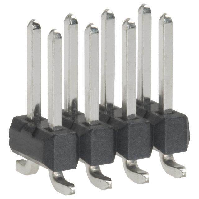
® ® ECG Fixed socket with two nuts, key (G) or keys (A…F and R) and straight contact for printed circuit (back panel mounting) Reference Dimensions (mm) Model Series A B e E M N S1 S3 ECG 00 10 10.2 M7x0.5 4.3 2.5 13.7 6.3 9 ECG 0B 12 12.4 M9x0.6 5.5 2.5 16.1 8.2 11 ECG 1B 16 15.8 M12x1.0 6.0 3.5 19.8 10.5 14 L N ECG XB 18 19.0 M14x1.0 6.0 3.5 20.0 12.5 17 S 3 M ECG 2B 20 19.2 M15x1.0 6.5 3.5 21.8 13.5 17 ECG 3B 24 25.0 M18x1.0 9.0 4.5 25.8 16.5 22 ø B e ø A ECG 4B 30 34.0 M25x1.0 10.0 4.5 29.8 23.5 30 ECG 5B 41 40.0 M35x1.0 9.0 5.0 36.8 33.5 – S 1 E maxi P1 Panel cut-out (page 157) P15 PCB drilling pattern (page 160) Note: The 3B, 4B and 5B series are delivered with a conical nut. The 5B series is delivered with a tapered washer and a round nut. Note: This contact type is available for Ell socket models fitted with female contacts. Length «L» depends on the number of contacts, see table on page 163. ECG Fixed socket with two nuts, key (G) or keys (A…F) with elbow (90°) contact for printed circuit (back panel mounting) Reference Dimensions (mm) N Model Series A B e E M S1 S3 max ECG 0B 12 12.4 M9x0.6 5.5 2.5 18.3 8.2 11 L N ECG 1B 16 15.8 M12x1.0 6.0 3.5 20.3 10.5 14 S 3 S 1 M ECG 2B 20 19.2 M15x1.0 6.5 3.5 22.3 13.5 17 ECG 3B 24 25.0 M18x1.0 9.0 4.5 27.8 16.5 22 ø B e ø A mini P1 Panel cut-out (page 157) 0 2 E maxi P17 PCB drilling pattern (page 164) 2 Note: The 3B series is delivered with a conical nut. Note: this female contact type is available for all back panel mounting socket models. Length «L» depends on the number of contacts, see PCB drilling pattern on page 164. For male contacts, sockets are available upon request, with J, K or L keys. EZG Straight socket for printed circuit, key (G) or keys (A, B) B 3 N H Reference Dimensions (mm) 5 0. ø 0.7 ø ø A Model Series A B H K N EZG 00 6.8 7 5.08 7 14 K P15+P16 PCB drilling pattern (pages 160 and 163) 20 www.lemo.com
® ® EZG Straight socket for printed circuit, key (G) or keys (A…F) Reference Dimensions (mm) Model Series A B H K N EZG 0B 9 10 7.62 8 15.0 B EZG 1B 11 12 7.62 8 19.0 1.6 L N H M EZG 2B 14 15 10.16 9 22.5 A ø P15+P16 PCB drilling pattern (pages 160 and 163) 2.2 Note: Length «L» depends on the number of contacts, see page 163. ø K Add letter «B» at the end of the reference to order with integrated harpoon pins (1.6 mm PCB thickness) (only for 0B and 1B series). EYG Fixed socket for printed circuit, nut fixing, key (G) or keys (A…F) (back panel mounting) Reference Dimensions (mm) Model Series A B C D e E M N P S1 EYG 0B 12 10 12.5 7.62 M9x0.6 2.6 2.5 15.0 6.0 8.2 EYG 1B 14 12 16.0 7.62 M11x0.5 5.0 3.5 19.0 10.0 – N EYG 2B 20 15 19.5 10.16 M15x1.0 7.5 3.5 22.5 13.5 13.5 L 9 P B S 1 M P1 Panel cut-out 0B and 2B series (page 157) 1.6 D M P10 Panel cut-out 1B series (page 157) ø C e ø A P15+P16 PCB drilling pattern (pages 160 and 163) 2 2. Note: Length «L» depends on the number of contacts, see page 163. ø E maxi Add letter «B» at the end of the reference to order with integrated harpoon pins (1.6 mm PCB thickness) (only for 0B and 1B series). PHG Free socket, key (G) or keys (A…M and R), cable collet Reference Dimensions (mm) Model Series A L S1 S2 PHG 001) 6.8 26.0 5.5 5 PHG 0B 9.5 35.5 8.0 7 ~L PHG 1B 12.5 40.5 10.0 9 PHG XB 13.0 46.0 11.0 10 A ø PHG 2B 16.5 47.0 13.0 12 PHG 3B 19.0 56.0 15.0 14 S 2 S 1 PHG 4B 26.0 73.0 21.0 20 PHG 5B 36.0 99.0 31.0 30 M1 Cable assembly (page 169) Note: 1) the surface design of the 00 series is different. www.lemo.com 21
® ® PHG Free socket, key (G) or keys (A…M), cable collet and nut for fitting a bend relief 2) Reference Dimensions (mm) Model Series A L S1 S2 PHG 00 1) 6.8 34.0 5.5 6 PHG 0B 9.5 34.5 8.0 7 ~L PHG 1B 12.5 39.5 10.0 9 PHG XB 13.0 49.5 11.0 10 A ø PHG 2B 16.5 46.0 13.0 12 PHG 3B S 2 S 1 19.0 54.5 15.0 15 PHG 4B 26.0 69.0 21.0 20 M1 Cable assembly (page 169) Note: 1)the surface design of the 00 series is different. Note: 2)to order, add a «Z» at the end of the reference. The bend relief must be ordered separately (see page 145). PNG Free socket, nut fixing, key (G) or keys (A…L and R), cable collet with lanyard release Reference Dimensions (mm) Model Series A B L N S1 S2 PNG 1B ~L 12.4 18.4 40.5 140 10 9 PNG 2B 16.5 22.5 47.0 160 13 12 PNG 3B 19.0 26.0 56.0 190 15 14 N ø A B PNG 4B 26.0 33.0 73.0 230 21 20 PNG 5B 36.0 43.0 99.0 300 31 30 S 2 S 1 M1 Cable assembly (page 169) Note:cable material: stainless steel with Polyamide sheath. 22 www.lemo.com
® ® PKG Fixed socket, nut fixing, key (G) or keys (A…M and R), cable collet Reference Dimensions (mm) Model Series A B e E L M S1 S2 S3 PKG 00 8 10.2 M7x0.5 6.5 26.0 1.0 6.3 5 9 ~L PKG 0B 10 12.4 M9x0.6 7.0 35.5 1.2 8.2 7 11 S 3 M PKG 1B 14 15.8 M12x1.0 7.5 40.5 1.5 10.5 9 14 PKG 2B 18 19.2 M15x1.0 8.5 47.0 1.8 13.5 12 17 A B PKG 3B e ø ø 22 25.0 M18x1.0 11.5 56.0 2.0 16.5 14 22 PKG 4B 28 34.0 M25x1.0 12.0 73.0 2.5 23.5 20 30 S 2 E maxi S 1 PKG 5B 40 40.0 M35x1.0 11.0 99.0 3.0 33.5 30 – P1 Panel cut-out (page 157) M1 Cable assembly (page 169) Note:the 5B series is delivered with a tapered washer and a round nut. PFG Fixed socket, with two nuts, key (G) or keys (A…M and R), cable collet (back panel mounting) Reference Dimensions (mm) Model Series A B e E L M S1 S2 S3 PFG 00 10 10.2 M7x0.5 5.3 26.0 2.5 6.3 5 9 PFG 0B ~L 12 12.4 M9x0.6 5.0 35.5 2.5 8.2 7 11 S 3 M PFG 1B 16 15.8 M12x1.0 5.0 40.5 3.5 10.5 9 14 PFG 2B 20 19.2 M15x1.0 6.5 47.0 3.5 13.5 12 17 PFG 3B ø B e ø A 24 25.0 M18x1.0 9.0 56.0 4.5 16.5 14 22 PFG 4B 30 34.0 M25x1.0 11.0 73.0 4.5 23.5 20 30 PFG 5B S 2 S 1 E maxi 41 40.0 M35x1.0 10.0 99.0 5.0 33.5 30 – P1 Panel cut-out (page 157) M1 Cable assembly (page 169) Note:the 3B, 4B and 5B series are delivered with a conical nut. The 5B series is delivered with a tapered washer and a round nut. PEG Fixed socket, nut fixing, key (G) or keys (A…L), cable collet (back panel mounting) ~L P S 1 M Reference Dimensions (mm) Model Series A B e E L M P S1 S2 S4 ø B e ø A PEG 3B 24 25 M18x1.0 5.0 56 4.5 12 16.5 14 20 PEG 4B 32 34 M25x1.0 12.5 73 5.0 20 23.5 20 27 S 2 E maxi S 4 P1 Panel cut-out (page 157) M1 Cable assembly (page 169) Note:the 4B series has an o-ring on the flange. www.lemo.com 23
® ® ll R Fixed coupler, nut fixing, key (G) or keys (A and J) at the flange end and keys (J, K or M) at the other end L S 3 M e ø A ø B E maxi S 1 Reference Contacts Dimensions (mm) Model Series Type A B e E L M S1 S3 RGG 0B G RGG G 1) female – female 12 13.8 M10x0.75 8.0 34 2.0 9.0 12 RGG 0B 2) female – female 12 13.8 M10x0.75 8.0 43 2.0 9.0 12 RJG 0B J RJG G male – female 12 13.8 M10x0.75 8.0 34 2.0 9.0 12 RGJ 0B female – male 12 13.8 M10x0.75 8.0 34 2.0 9.0 12 RAK 0B G RGJ J female – male 12 13.8 M10x0.75 8.0 34 2.0 9.0 12 RGM 0B female – male 12 13.8 M10x0.75 8.0 34 2.0 9.0 12 RGG 1B A RAK K 3) female – female 16 19.2 M14x1.00 8.5 47 2.5 12.5 17 RJG 1B male – female 16 19.2 M14x1.00 8.5 39 2.5 12.5 17 RGJ 1B female – male 16 19.2 M14x1.00 8.5 39 2.5 12.5 17 G RGM M RJG 2B male – female 20 21.5 M16x1.00 12.0 44 4.0 15.0 19 RGJ 2B female – male 20 21.5 M16x1.00 12.0 44 4.0 15.0 19 Example RGJ 3B female – male 25 27.0 M20x1.00 32.0 53 4.0 18.5 24 RGJ RGJ 4B female – male 34 34.0 M25x1.00 50.0 65 4.0 23.5 30 Plug with key G Plug with key J P4 Panel cut-out (page 157) Note: 1)only available with two contacts. 2)RGG.0B only available from 3 till 5 contacts. Alignment key see page 36. 3)RGG.1B only available till 7 contacts. For this fixed coupler, the first contact type mentioned is always the one at the flange end. On request, these couplers can be produced in other series, with other keys. 24 www.lemo.com
® ® Elbow socket models Technical Characteristics Types Materials and Treatment Surface Component Material Treat. (µm) Cu Ni Au PPS – Housing Brass 0.5 3 – Metallic parts Brass 0.5 3 – Earthing crown Bronze 0.5 3 – Insulator PEEK – Series Series Type 1 2 1 Female contact Bronze 0.5 3 1.5 1 00 0B, 1B 302 2 Note: 2 The surface treatment standards are as follows: 1 2 1 2 – Nickel: SAE AMS QQ N 290. – Gold: ISO 27874 1 00 0B, 1B 303 2 3 Electrical 3 3 0000 1 241 323 00BB,, 11BB 1 142 233 330045 2103054 02B213,1 14435B Model Series Types Test voltage(kV rms)1)Contact-contact Test voltage(kV rms)1)Contact-shell Rated current (A)1) 5 4 5 4 EPG-XBG 00 302-303-304-305 1.00 1.00 2.0 1 2 3 1 6 EPG-EXG 0B 302 1.45 1.20 4.5 0B, 1B 306 2 5 3 4 EPG-EXG 0B 303 1.70 1.60 4.5 6 5 4 EPG-EXG 0B 304 1.30 1.10 4.5 1 2 3 1 6 0B, 1B 7 307 2 7 5 EPG-EXG 0B 305 1.25 1.20 4.5 3 4 6 5 4 EPG-EXG 0B 306 1.25 1.20 2.5 2 3 4 EPG-EXG 0B 307 1.00 1.00 2.0 1 1B 1 8 308 3248576 EPG-EXG 0B 309 0.60 0.50 1.5 7 6 5 EPG-EXG 1B 302 1.70 1.45 4.5 3 1 2 4 0B 9 309 21987 EPG-EXG 1B 303 1.60 1.85 4.5 3 6 8 7 5 4 5 EPG-EXG 1B 304 1.70 1.80 4.5 6 3 1 2 4 EPG-EXG 1B 305 1.30 1.55 4.5 1 8 1B 9 10 310 32 190 67 EPG-EXG 1B 306 1.35 1.45 4.5 4 5 8 7 5 6 EPG-EXG 1B 307 1.45 1.45 2.0 12345 1B11 1213 314 3212111110498 EPG-EXG 1B 308 1.30 1.30 2.0 14 4 13 7 5 6 EPG-EXG 1B 310 1.00 1.00 1.5 109876 EPG 1B 314 1.00 1.30 1.0 Note: 1) see calculation method, caution and suggested standard on page 190. Note: numbering sequence shown is for female contacts (G keying), for inverted contacts please contact factory. P18 PCB drilling pattern (page 165) P19 PCB drilling pattern (page 165) www.lemo.com 25
® ® EPG Elbow (90°) socket for printed circuit, key (G) or keys (A…F) (solder or screw fixing) 7 12. ø A L N K Dimensions (mm) Part number A D H I K L N I H EPG.1B.314.NLN 11 21 7.7 14.3 19 36 15.4 3 ø 0.7 ø 0.6 M 1.6 P20 PCB drilling pattern (page 165) D Note: to replace the 4 ground pins by 4 screws (M1.6) add an «S» to the end of the part number. (e.g.: EPG.1B.314.NLNS) EPG Elbow (90°) socket for printed circuit, key (G) or keys (A…F) (solder or screw fixing) Dimensions (mm) Part number A D H I K L N R EPG.00.302.HLN EPG.00.303.HLN 6.8 11.5 3.5 7.0 8.7 19 7.1 5.08 EPG.00.304.HLN EPG.00.305.HLN EPG.0B.302.HLN EPG.0B.303.HLN R EPG.0B.304.HLN A ø EPG.0B.305.HLN 9.0 14.6 6.7 12.6 13.3 25 11.7 7.62 EPG.0B.306.HLN EPG.0B.307.HLN L EPG.0B.309.HLN N K EPG.1B.302.HLN I H EPG.1B.303.HLN EPG.1B.304.HLN 0) B-1B) ø 0.7 M 1.6 D EPG.1B.305.HLN 11.0 16.6 7.5 14.0 13.3 27 12.6 7.62 3.0 (03.2 (0 øø 00..57 ((000B)-1B) ø 2.2 EPG.1B.306.HLN EPG.1B.307.HLN EPG.1B.308.HLN EPG.1B.310.HLN Note: In the 0B and 1B series, it is possible to replace the 4 P18 PCB drilling pattern 00 series (page 165) ground pins by 4 screws (M1.6) add an «S» to the end of the part number. (e.g.: EPG.0B.307.HLNS). A second alternative is to add an «B» at the end of the part P19 PCB drilling pattern 0B, 1B series (page 165) number (EPG.0B.307.HLNB), the connector is delivered with integrated harpoon pins for rapidly assembly (1.6 mm PCB thickness) 26 www.lemo.com
® ® EXG Elbow (90°) socket for printed circuit with two nuts, key (G) or keys (A…F) (solder or screw fixing) (back panel mounting) XBG Elbow (90°) socket fixing nut for printed circuit, key (G) or keys (A, B) (back panel mounting) Dimensions (mm) Part number A B D e E H I K L M N R S3 XBG.00.302.HLN XBG.00.303.HLN 1010.211.5 M7x0.5 2.1 3.5 7.0 8.7 19 2.5 7.15.08 9 XBG.00.304.HLN EXG.0B.302.HLN EXG.0B.303.HLN EXG.0B.304.HLN N R EXG.0B.305.HLN 1212.414.6 M9x0.6 4.5 6.712.613.3 25 2.511.77.62 11 EXG.0B.306.HLN K EXG.0B.307.HLN L EXG.0B.309.HLN S 3 M EXG.1B.302.HLN EXG.1B.303.HLN I H e ø A EXG.1B.304.HLN EXG.1B.305.HLN B B) M 1.6 Eø maxi EXG.1B.306.HLN 1415.016.6M11x0.5 7.5 7.514.013.3 27 3.512.67.62 13 0 (00) 2 (0B-1 øø 00..57 ((000B)-1B) D EXG.1B.307.HLN 3.3. EXG.1B.308.HLN EXG.1B.310.HLN Note:In the 0B and 1B series, it is possible to replace the 4 P2 Panel cut-out 00, 0B series (page 157) ground pins by 4 screws (M1.6) add an «S» to the end of the part number. (e.g.: EXG.0B.307.HLNS). P10 Panel cut-out 1B series (page 157) P18 PCB drilling pattern 00 series (page 165) P19 PCB drilling pattern 0B, 1B series (page 165) www.lemo.com 27
® ® Plastic housing models These connectors are particularly recommended for all applications requiring maximum electrical insulation when mated. The design, including a latch sleeve and a metal earthing crown, guarantees EMC screening efficiency to meet most requirements. Technical Characteristics Mechanical and Climatical Value Characteristics Standard PEEK PSU PPSU Colour natural (beige) white or grey cream – Endurance1) > 5000 cycles > 5000 cycles > 5000 cycles IEC 60512-5 test 9a Humidity up to 95% at 60° C – Temperature range - 50° C/+ 250° C - 50° C/+ 150° C - 50° C/+ 180° C – Sterilization resistance2) > 200 cycles ~20 cycles > 100 cycles IEC 60601-1 § 44.7 Resistance to solvents very good limited good – Note: 1)see page 189, contact resistance after mating cycles. See page 185, mechanical endurance latching force. 2)Steam sterilization. FGG Straight plug, key (G or J), cable collet, PEEK outer shell ~L ~M Reference Dimensions (mm) A Model Series A L M S2 ø FGG 0B 11.0 37.4 27.4 8 FGG 1B S 2 13.5 43.0 32.0 10 FGG 3B 19.0 62.0 47.0 15 FGG 4B 26.0 78.5 60.5 20 M1 Cable assembly (page 169) FGG Straight plug, key (G or J), cable collet, PEEK outer shelland nut for fitting a bend relief 1) ~L ~M Reference Dimensions (mm) A Note on availability ø Model Series A L M S2 FGG 1B 13.5 42.2 31.2 10 for all collet type S 2 FGG 4B 26.0 83.2 65.2 20 only from collet M82 and up M1 Cable assembly (page 169) Note: 1)to order, add a «Z» at the end of the reference. The bend relief must be ordered separately (see page 145). 28 www.lemo.com
® ® FGY Straight plug, keys (Y), cable collet and PSU or PPSU outer shell ~L Reference Dimensions (mm) ~M Model Series A L M S2 ø A FGY 2B 16.5 50.5 39.5 13 FGY 3B S 2 19.0 58.0 43.0 15 FGY 4B 26.0 76.2 58.2 20 M1 Cable assembly (page 169) FGY Straight plug, keys (Y), cable collet and PSU or PPSU outer shell and nut for fitting a bend relief 1) Reference Dimensions (mm) ~L Note on availability Model Series A L M S2 ~M FGY 2B 16.5 49.5 38.5 13 only for collet M42 and up A FGY 3B ø 19.0 56.5 41.5 15 only for collet D62 and up FGY 4B 26.0 74.4 56.4 20 only for collet D82 and up S 2 M1 Cable assembly (page 169) Note: 1)to order, add a «Z» at the end of the reference. The bend relief must be ordered separately (see page 145). ENG Fixed socket with earthing tag, nut fixing, key (G or J), PEEK outer shell Reference Dimensions (mm) L maxi Model Series A B e E L M N1) S1 S3 N ENG 0B S 3 M 11 12.5 M9x0.6 6.4 20.7 1.8 16.5 8.2 11 ENG 1B 14 15.8 M12x1.0 7.5 23.0 1.5 21.1 10.5 14 ø B e ø A ENG 3B 22 25.0 M18x1.0 11.5 30.7 2.0 28.1 16.5 22 ENG 4B 28 34.0 M25x1.0 12.0 35.7 2.5 32.6 23.5 30 E maxi S 1 P1 Panel cut-out (page 157) Note: 1)maximum length with crimp contacts. ENY Fixed socket with earthing tag, nut fixing, keys (Y), PSU or PPSU outer shell Reference Dimensions (mm) L maxi Model Series A B e E L M N1) S1 S3 N ENY 2B S 3 M 18 19.2 M15x1.0 8.5 26.7 1.8 24.6 13.5 17 ENY 3B 22 25.0 M18x1.0 11.5 30.7 2.0 28.1 16.5 22 ø B e ø A ENY 4B 28 34.0 M25x1.0 12.0 35.7 2.5 32.6 23.5 30 P1 Panel cut-out (page 157) E maxi S 1 Note: 1)maximum length with crimp contacts. Other models with plastic outer shell are available on request. www.lemo.com 29
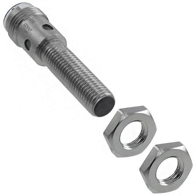
® ® Watertight or vacuumtight models These plug, socket and coupler models allow the device on which they are fitted to reach a protection index of IP68 as per IEC 60529. They are fully compatible with plugs of the same series and are widely used for portable radios, military, laboratory equipment, aviation, etc. These models are identified by a letter «P» at the end of the reference. Most of these models are also available in a vacuumtight version. Such models are identified by an additional letter «V» at the end of the part number (certificate on request). Epoxy resin is used to seal these models. Technical Characteristics Mechanical and Climatical Characteristics Value Standard Characteristics Value Standard Endurance1) > 5000 cycles IEC 60512-5 test 9a 00 60 bar IEC 60512-7 test 14d Humidity up to 95% at 60° C 0B 60 bar IEC 60512-7 test 14d 00 to 1B - 20° C/+ 100° C 1B 60 bar IEC 60512-7 test 14d Temperature range Maximum operating 2B to 5B - 20° C/+ 80° C 2B 40 bar IEC 60512-7 test 14d pressure3) Salt spray corrosion test4) > 1000h IEC 60512-6 test 11f 3B 30 bar IEC 60512-7 test 14d Climatical category 20/80/21 IEC 60068-1 4B 15 bar IEC 60512-7 test 14d Leakage rate (He)2) < 10-7 mbar.l.s-1 IEC 60512-7 test 14b 5B 5 bar IEC 60512-7 test 14d Note: 1) see page 189, contact resistance after mating cycles. See page 185, mechanical endurance latching force. 2) only for vacuumtight models. Residual traces of grease used during (He) leak testing are on the o-ring. Please contact us for further details. 3) this value corresponds to the maximum allowed pressure difference for the assembled socket. 4) for chrome plated product (« C » material code). YHG Fixed plug, nut fixing, non-latching, key (G) or keys (A…M) Reference Dimensions (mm) L maxi Model Series A B e E L M S1 S3 S 3 M YHG 0B 13 12.4 M9x0.6 2.4 24.1 14.2 8.2 11 YHG 1B 16 15.8 M12x1.0 3.9 28.0 16.2 10.5 14 ø B e ø A YHG 2B 19 19.2 M15x1.0 5.5 33.1 17.8 13.5 17 YHG 3B 22 25.0 M18x1.0 5.1 38.2 22.2 16.5 22 E maxi S 1 P9 Panel cut-out (page 157) Note: this model does not include an O-ring behind the flange, it ensures only IP61 protection index. Consequently, it is not vacuumtight. Water- tightness (when mated) is only ensured with HHG and HCG sockets. 30 www.lemo.com
® ® HGG Fixed socket, nut fixing, key (G) or keys (A…Mand R), watertight or vacuumtight Reference Dimensions (mm) Model Series A B e E L M S1 S3 HGG 00 L maxi 11 10.2 M7x0.5 8.0 18.0 1.5 – 9 S 3 M HGG 0B 13 12.4 M9x0.6 7.0 21.5 3.0 8.2 11 HGG 1B 18 15.8 M12x1.0 7.0 26.6 4.5 10.5 14 HGG 2B ø B e ø A 20 19.2 M15x1.0 8.0 31.6 4.0 13.5 17 HGG 3B 25 25.0 M18x1.0 11.5 36.1 4.0 16.5 22 HGG 4B E maxi S 1 34 34.0 M25x1.0 11.0 43.1 4.0 23.5 30 HGG 5B 45 40.0 M35x1.0 11.0 53.6 5.0 33.5 – P9 Panel cut-out (page 157) Note:the 5B series is delivered with a tapered washer and a round nut. HNG Fixed socket, nut fixing, with earthing tag, key (G) or keys (A…M), watertight or vacuumtight L maxi S 3 M ø B e ø A Reference Dimensions (mm) E maxi S 1 Model Series A B e E L M S1 S3 HNG 0B 13 12.4 M9x0.6 7 21.5 3 8.2 11 P9 Panel cut-out (page 157) HHG Fixed socket, nut fixing, key (G) or keys (A…M), watertight or vacuumtight (watertight when mated) L maxi Reference Dimensions (mm) S 3 M Model Series A B e E L M S1 S3 HHG 0B 13 12.4 M9x0.6 7.0 24.5 4.8 8.2 11 ø B e ø A HHG 1B 18 15.8 M12x1.0 7.0 30.3 5.2 10.5 14 HHG 2B 22 19.2 M15x1.0 8.0 35.6 6.0 13.5 17 HHG 3B E maxi S 1 25 25.0 M18x1.0 11.5 41.3 7.2 16.5 22 P9 Panel cut-out (page 157) Note:this model ensures watertightness (IP66) in the mating area when mated with FGG or similar plug. www.lemo.com 31
® ® HCG Fixed socket, nut fixing, key (G) or keys (A…M), watertight or vacuumtight (watertight when mated) (back panel mounting) L maxi P Reference Dimensions (mm) F maxi M Model Series A B C e e1 E F L M P S1 HCG 0B ø B ø C e 1 e ø A HCG 1B 18 18 12.0 M14x1.0 M9x0.6 3.9 1.0 24.5 3.5 7.5 12.5 20 20 14.5 M16x1.0 M12x1.0 6.2 2.0 30.3 3.5 10.0 14.5 HCG 2B 24 24 17.5 M19x1.0 M14x1.0 6.7 1.5 35.6 3.5 11.3 17.0 S 1 E maxi P3 Panel cut-out (page 157) Note: this model ensures watertightness (IP66) in the mating area when mated with FGG or similar plug. HEG Fixed socket, nut fixing, key (G) or keys (A…M), watertight or vacuumtight (back panel mounting) L maxi P S2 S1 M Reference Dimensions (mm) Model Series A B e E L M P S1 S2 HEG 00 ø B e ø A 10 11 M7x0.5 2.5 18.2 2.5 6.0 6.3 – HEG 0B 12 13 M9x0.6 5.5 21.5 2.5 9.0 8.2 – HEG 1B E maxi 16 18 M12x1.0 6.5 26.6 3.5 11.0 10.5 – HEG 2B 20 20 M15x1.0 5.0 31.6 3.5 9.6 13.5 15 P9 Panel cut-out (page 157) HMG Fixed socket with earthing tag, nut fixing, key (G) or keys (A…M), watertight or vacuumtight (back panel mounting) Reference Dimensions (mm) L maxi Model Series A B e E L M P S1 HMG 00 P 10 11 M7x0.5 2.5 18.0 2.5 6.0 6.3 S1 M HMG 0B 12 13 M9x0.6 5.5 21.5 2.5 9.0 8.2 HMG 1B 16 18 M12x1.0 5.5 26.6 3.5 11.0 10.5 ø B e ø A HMG 2B1) 20 20 M15x1.0 5.5 31.6 3.5 9.6 13.5 HMG 3B 24 25 M18x1.0 7.5 36.1 4.5 14.0 16.5 E maxi P9 Panel cut-out (page 157) Note: 1)the surface design of the 2B series is different. Note: The 3B series is delivered with a conical nut and without washer. 32 www.lemo.com
® ® ll S Fixed coupler, nut fixing, key (G) or keys (A, B, J, K and L) at the flange end and key (G) or keys (A, B, J, K and L) at the other end, watertight or vacuumtight L S 3 S 1 M ø B e ø A E maxi Reference Contacts Dimensions (mm) Model Series Type A B e E L M S1 S3 SGJ 0B female – male 14 13.8 M10x0.75 17 34 2.0 9.0 12 SJG 0B male – female 14 13.8 M10x0.75 17 34 2.0 9.0 12 SGJ 1B female – male 17 15.8 M12x1.00 28 39 2.5 10.5 14 G SGJ J SJG 1B male – female 17 15.8 M12x1.00 28 39 2.5 10.5 14 SGJ 2B female – male 20 21.5 M16x1.00 25 44 4.0 15.0 19 J SJG G SJG 2B male – female 20 21.5 M16x1.00 25 44 4.0 15.0 19 SGJ 3B female – male 25 27.0 M20x1.00 30 53 4.0 18.5 24 K SKA A SJG 3B male – female 25 27.0 M20x1.00 30 53 4.0 18.5 24 SAK 3B female – male 25 27.0 M20x1.00 30 53 4.0 18.5 24 L SLB B SBL 3B female – male 25 27.0 M20x1.00 30 53 4.0 18.5 24 SAK 4B female – male 34 34.0 M25x1.00 50 65 4.0 23.5 30 A SAK K SBL 4B female – male 34 34.0 M25x1.00 50 65 4.0 23.5 30 SGJ 4B female – male 34 34.0 M25x1.00 50 65 4.0 23.5 30 B SBL L SJG 4B male – female 34 34.0 M25x1.00 50 65 4.0 23.5 30 SGJ 5B female – male 45 40.0 M35x1.00 58 80 5.0 33.5 – SJG 5B male – female 45 40.0 M35x1.00 58 80 5.0 33.5 – SKA 5B male – female 45 40.0 M35x1.00 58 80 5.0 33.5 – Example SLB 5B male – female 45 40.0 M35x1.00 58 80 5.0 33.5 – SGJ SAK 5B Plug with key G Plug with key J female – male 45 40.0 M35x1.00 58 80 5.0 33.5 – SBL 5B female – male 45 40.0 M35x1.00 58 80 5.0 33.5 – P4 Panel cut-out (page 157) Alignment key see page 36. P9 Panel cut-out 1B series (page 157) Note:The 5B series is delivered with a round nut. Note:for this fixed coupler, the first contact type mentioned is always the one at the flange end. On request these couplers can be produced in other series, with other keys. www.lemo.com 33
® ® Bridge models Technical Characteristics Mechanical and Climatical Electrical Characteristics Value Standard Characteristics Value Standard Endurance1) > 1000 cycles IEC 60512-5 test 9a Contact resistance < 6 mΩ IEC 60512-2 test 2a Working temperature maximum 90° C o eo e 2) Note:1)see page 189, contact resistance after mating cycles. See page on er ag1) A) M18a5,t emreicahlasn aicnald e nTdrueraantcme elantcthing force. Part number Series Audio-M Audio-St Test volt(kV rms) Rated current ( S u r f a c e t reat. (µm) CFF.0B.302.PLCG 0B l – 1.05 4 Component Material Cu Ni Cr Au CRG.0B.302.PLEG l 0B – 1.05 4 Plastic housing Polyamide – CFF.0B.303.PLCG l 0B – 0.80 4 Brass 0.5 3 – – CRG.0B.303.PLEG l Metallic parts 0B – 0.80 4 Brass 0.5 3 0.3 – CRG.0B.306.PLEG l 0B – 0.40 2 Insulator PEEK – CFF.1B.303.PLCG l 1B – 1.25 5 Male contact Brass 0.5 3 – 1.0 CRG.1B.303.PLEG l 1B – 1.25 5 Female contact Bronze 0.5 3 – 1.5 CFF.1B.306.PLCG l 1B – 0.80 3 Note:the surface treatment standards are as follows: CRG.1B.306.PLEG l – Nickel: SAE AMS QQ N 290, chrome: SAE AMS 2460, gold: ISO 27874 1B – 0.80 3 Note:the last letter of the part number indicates the colour of the housing. Note: Ex. G (standard) is grey. To obtain another colour, replace this letter by 1)see calculation method, caution and suggested standard on page 190. the letter corresponding to the selected colour (see table on page 72). 2)lowest measured value; contact to contact or contact to shell. CFF Bridge plug with two non-latching plugs CRG Bridge plug with two non-latching plugs, and monitoring socket, key (G) or keys (A…M) CFF CRG A M maxi Dimensions (mm) Model Series H B N A B H L M N CFF-CRG 0B 13.5 14 27.5 37.2 27.2 22.5 CFF-CRG 1B 15.0 20 35.0 42.0 31.0 22.0 L maxi Note:in order to provide the user with a coding system, the bridge plug housing, the double panel washers and the bend reliefs are available in nine colours. 34 www.lemo.com
® ® Threaded-latching models FVG Straight plug, key (G) or keys (B), cable collet ~L ~M Reference Dimensions (mm) A ø Model Series A L M S1 S2 FVG 00 S1 S2 9 28.5 24 5 8 Note:to be ordered with nut for fitting a bend relief to obtain the rating IP 64. ESG Fixed socket with two round nuts, key (G) or keys (B), long threaded shell (back panel mounting) L maxi N M 3.2 mini 1) Reference Dimensions (mm) Model Series A B C e E L M N ø C ø B e ø A ESG 00 9 9 9.5 M7x0.5 3.2 15.5 2 13.7 E maxi P2 Panel cut-out (page 157) Note:1)minimum length of free thread to ensure mating. FVB Straight plug, keys (B), short shell for special cable crimping and for fitting a bend relief L M Reference Dimensions (mm) Model Series A L M A ø FVB 00 9 20 15.4 Note:part number for microphone applications: FVB.00.303.NLAE24. l After assembly the special bend relief GMF.00.018.D (to be ordered separately) is to be fitted. XRB Elbow (90°) socket for printed circuit, keys (B), short shell with one nut, screw fixing (back panel mounting) 1.2 2.05 8 5.5== L P Reference Dimensions (mm) M 3.2 mini 1) Model Series A e I L M P XRB 00 10 M7x0.5 7 14 2.5 7 I e ø A P2 Panel cut-out (page 157) 3 2 x M 1.4 P18 PCB drilling pattern for contact only (page 165) Note:1)minimum length of free thread to ensure mating. www.lemo.com 35
® ® Alignment Key (B series) Alignment Key and Polarized Keying System B series connector model part numbers are composed of three letters. The LAST LETTER indicates the key position and the contact type (male or female). Front view of a socket es Series es Series Contact type Nb of gl Nb of gl Ref. n Ref. n Note keys A keys A 00 0B 1B XB 2B 3B 4B 5B Plug Socket G G l 1 – 0° 0° 0° 1 – 0° 0° 0° 0° 0° male female A α A α l 2 30° 30° 30° 2 30° 30° 30° 30° 30° male female α B α B α l 2 60° 60° 60° 2 – 45° 45° 45° 45° male female β(5B) β CD 2 αβ – 90° 90° CD 2 αγ – 60° 60° 60° 60° male female ll 2 – 135° 135° 2 – 95° 95° 95° 95° male female δ E β E β l 2 – 145° 145° 2 120° 120° 120° 120° 120° male female F β F β l 2 – 155° 155° 2 – 145° 145° 145° 145° male female J γ J α l γ 2 45° 45° 45° 2 – 37.5° 37.5° 37.5° 37.5° female male K γ K α l 2 – 70° 70° 2 – 52.5° 52.5° 52.5° 52.5° female male L γ L γ l 2 – 80° 80° 2 – 70° 70° 70° 70° female male M δ M l 2 – 110° – 2 – – – – – – female male Y 3 – – – – Y 3 β – 112.5° 126° 112.5° – male female l1) 3 – – – – 3 γ – 100° 102° 147.5° – male female l1) Front view of a socket es Series es Series Contact type Nb of gl Nb of gl Ref. n Ref. n Note keys A keys A α 00 0B 1B XB 2B 3B 4B 5B Plug Socket β α α l 5 – – – 5 – – – – 95° male female β β l γ R 5 – – – R 5 – – – – 115° male female δ γ γ l 5 – – – 5 – – – – 20° male female δ δ l 5 – – – 5 – – – – 30° male female Note: FTG, FGY, ENY models are not available with all the keys. Please consult pages corresponding to these models. ll ll For R models see explanation on page 24 and for S models see explanation on page 33. Note: 1)only FGY and ENY models are available. l l First choice alternative Special order alternative 36 www.lemo.com
® ® K Series K series connectors have been specifically designed for outdoor applications. They include an inner sleeve and two seals to prevent penetration of solids or liquids into the housing formed by the plug, free socket, fixed socket or coupler. All models of this series are watertight when mated to give a protection index of IP68 as per IEC 60529 standard (in mated condition) when correctly assembled to an appropriate cable (IP66 otherwise). K series connectors have the same insulators as the B series and have the following main features: – security of the Push-Pull latching system – watertight connection (IP 68/IP 66) – multipole types 2 to 64 contacts – solder, crimp or print (straight or elbow) contacts – keying system («G» key standard) – multiple key options to avoid cross mating for connector alignment of similar connectors – 360° screening for full EMC shielding – high packing density for space savings – rugged housing for extreme working conditions. Metal housing models (page 39) Fixed plugs Straight plugs Fixed sockets Free sockets Free coupler FXG FGG EGG EBG PHG TGL* T-plug with sockets (90°) FAG FGG PHG ENG EDG Elbow plug FGG PHG FTG* FPG EEG EHG Fixed sockets FNG FHG EEG EVG* PKG EEG PBG Watertight or vacuumtight models (page 47) Fixed sockets Fixed coupler PEG HGG HEG HMG S•• Note: * Contact LEMO for details. www.lemo.com 37
® ® Part Numbering System Plug F G G . 3 K . 3 1 0 . C L A C 6 5 Free socket P H G . 3 K . 3 1 0 . C L L C 6 5 Z Variant: (page 71) Cable ø: (page 68) Collet type: (page 68) Fixed socket E G G . 3 K . 3 1 0 . C Y M Coupler S L G . 3 K . 3 1 0 . T L A PV Model: (page 39) Variant: (page 71) Alignment key: (page 49) Contact: (page 64) Series: (page 39) Insulator: (page 64) Insert configuration: (page 57) Housing: (page 64) FGG.3K.310.CLAC65 = straight plug with key (G) and cable collet, 3K series, multipole type with 10 contacts, outer shell in chrome- plated brass, PEEK insulator, male solder contacts, C type collet for 6.5 mm diameter cable. PHG.3K.310.CLLC65Z = free socket with key (G) and cable collet, 3K series, multipole type with 10 contacts, outer shell in chrome- plated brass, PEEK insulator, female solder contacts, C type collet for 6.5 mm diameter cable and nut for fitting a bend relief. EGG.3K.310.CYM = fixed socket, nut fixing, with key (G), 3K series, multipole type with 10 contacts, outer shell in chrome-plated brass, PEEK extended insulator, female crimp contacts. SLG.3K.310.TLAPV = fixed coupler, nut fixing, keys (L) on the flange end and key (G) at the other end, 3K series, multipole type with 10 contacts, outer shell in stainless steel, PEEK insulator, male-female contacts, vacuumtight. Part Section Showing Internal Components Straight plug 1 Fixed socket outer shell 2 5 2 3 4 7 7 1 6 8 2 3 7 6 4 1 9 11 12 10 5 latch sleeve 1 outer shell 3 inner shell 2 earthing crown 4 retaining ring 3 5 retaining ring collet nut 4 hexagonal nut 6 split insert carrier 5 insulator 7 insulator 6 8 female contact male contact 7 9 o-ring earthing cone 10 collet 11 gasket 12 washer 38 www.lemo.com
® ® Metal housing models Technical Characteristics Mechanical and Climatical Electrical Characteristics Value Standard Characteristics Value Standard Endurance1) > 5000 cycles IEC 60512-5 test 9a at 10 MHz > 95 dB IEC 60169-1-3 Shielding efficiency Humidity up to 95% at 60° C at 1 GHz > 80 dB IEC 60169-1-3 Temperature range2) - 55° C, + 200° C Note: the various tests have been carried out with FGG and EGG connector Resistance to vibrations 10-2000 Hz, 15g IEC 60512-4 test 6d pairs, with chrome-plated brass shell, PEEK insulator and silicone O-ring. Detailed electrical characteristics, as well as materials and treatment are Shock resistance 100 g, 6 ms IEC 60512-4 test 6c presented in the chapter Technical Characteristics on page 182. Salt spray corrosion test4) > 1000h IEC 60512-6 test 11f 1) see page 189, contact resistance after mating cycles. See page 185, mechanical endurance latching force. Protection index (mated)3) IP 68/IP 66 IEC 60529 2) minimum operating temperature is -20°C for sockets fitted with an FPM (Viton®) O-ring. Climatical category 50/175/21 IEC 60068-1 3) IP68 achieved providing that the cable is perfectly circular and that assembly process ensures a high integrity seal. 4) for chrome plated product (« C » material code). FGG Straight plug, key (G) or keys (A to F, L and R), cable collet Reference Dimensions (mm) Model Series A L M S2 ~L FGG 0K 11 34 23.0 8 ~M FGG 1K 13 42 28.0 9 FGG 2K 16 52 36.0 12 A ø FGG 3K 19 61 41.0 15 S 2 FGG 4K 25 71 50.5 19 FGG 5K 38 92 67.0 30 M1 Cable assembly (page 172) FGG Straight plug, key (G) or keys (A to F, L and R), cable collet and oversize cable collet 1) Reference Dimensions (mm) Model Series A B L M S1 S2 FGG 1K 13 14.5 60.0 46 12 12 FGG 2K 16 17.0 68.0 52 15 15 ~L FGG 3K 19 22.0 85.0 65 19 19 ~M FGG 4K 25 36.0 119.5 99 30 32 B A ø ø M2 Cable assembly (page 173) Note: 1) correspond to K type of collet, the fitting of oversize collets onto S 2 S 1 this model allows them to be fitted to the cables that can be accommodated by the next housing size up (see page 68). www.lemo.com 39
® ® FGG Straight plug, key (G) or keys (A to F, L and R),cable collet and nut for fitting a bend relief 1) Reference Dimensions (mm) Model Series A L M S2 FGG 0K ~L 11 34 23.0 7 ~M FGG 1K 13 42 28.0 9 FGG 2K 16 52 36.0 12 A ø FGG 3K 19 60 40.0 15 FGG 4K S 2 25 71 50.5 19 M1 Cable assembly (page 172) Note: 1)to order, add a «Z» at the end of the reference. The bend relief must be ordered separately (see page 145). FNG Straight plug, key (G) or keys (A to F and L), cable collet and lanyard release ~L ~M Reference Dimensions (mm) Model Series A B L M N S2 FNG 2K 16 22 52 36.0 160 12 N ø A B FNG 4K 25 32 71 50.5 230 19 M1 Cable assembly (page 172) S 2 Note:cable material: stainless steel with Polyamide sheath FXG Fixed plug with round flange, key (G) or keys (A to F, L and R) and screw fixing Reference Dimensions (mm) ~ L Model Series A B G H L M P S2 FXG 3K P 38 22.5 3.4 20.6 61 10.0 30.0 15 H M FXG 4K 47 28.5 3.4 27.0 71 11.0 32.0 19 FXG 5K 65 42.5 4.4 38.0 100 12.5 38.5 30 ø G ø B ø A P6 Panel cut-out (page 159) Note:this model does not include an O-ring behind the flange, it allows S 2 the device on which it is fitted to reach only IP50 protection index. It does not have a cable collet. 40 www.lemo.com
® ® FAG Fixed plug, nut fixing, non-latching, key (G) or keys (A to F, L and R) Reference Dimensions (mm) L maxi Model Series A B e E L M N1) S1 S3 FAG 1K N 20 21.5 M16x1.0 2.3 22.6 16.0 22.5 14.5 19 S 3 FAG 2K M 25 27.0 M20x1.0 4.5 33.6 18.0 28.3 18.5 24 FAG 3K 31 34.0 M24x1.0 4.0 34.3 22.5 33.8 22.5 30 FAG 4K B A 37 40.5 M30x1.0 4.0 35.3 23.0 36.3 28.5 36 ø e ø FAG 5K 55 54.0 M45x1.5 4.0 43.5 28.5 42.3 42.5 – E maxi S 1 P1 Panel cut-out (page 159) Note:The 1K series is delivered with a locking washer. The 5K series is delivered with a round nut. Note:1)maximum length with crimp contacts. FPG Elbow (90°) plug, key (G) or keys (A to F, L and R), cable collet ~L S 1 ~M ø A Reference Dimensions (mm) H Model Series A D H L M S1 S2 S3 ~ S 3 FPG 0K 11 7.3 25 36 25 9 8 8 S 2 FPG 1K 13 8.7 33 42 28 11 9 10 D FPG 2K 16 10.2 40 51 35 14 12 13 M3 Cable assembly (page 172) FHG Elbow (90°) plug, key (G) or keys (A to F, L and R), cable collet ~L S 1 ~M A ø H Reference Dimensions (mm) ~ S 3 Model Series A D H L M S1 S2 S3 S 2 FHG 3K 21.0 11.5 47 60 40.0 18 15 15 D FHG 4K 27.5 15.5 57 72 51.5 24 19 20 M3 Cable assembly (page 172) www.lemo.com 41
® ® EGG Fixed socket, nut fixing, key (G) or keys (A to F, L and R) Reference Dimensions (mm) Model Series A B e E L M N1) S1 S3 L maxi EGG 0K 18 19.2 M14x1.0 6 21.7 4.0 20.1 12.5 17 N EGG 1K S 3 M 20 21.5 M16x1.0 9 27.0 4.5 25.1 14.5 19 EGG 2K 25 27.0 M20x1.0 9 30.7 5.0 28.6 18.5 24 EGG 3K 31 34.0 M24x1.0 11 36.2 6.0 33.6 22.5 30 ø B e ø A EGG 4K 37 40.5 M30x1.0 9 40.2 6.5 38.6 28.5 36 EGG 5K 55 54.0 M45x1.5 10 47.5 9.0 43.6 42.5 – E maxi S 1 P1 Panel cut-out (page 159) Note:The 5K series is delivered with a round nut. Note:1)maximum length with crimp contacts. ENG Fixed socket, nut fixing, key (G) or keys (A to F, L and R) and earthing tag L maxi N S 3 M ø B e ø A Reference Dimensions (mm) Model Series A B e E L M N1) S1 S3 ENG 3K E maxi S 1 31 34 M24x1.0 11.3 36.2 6 33.6 22.5 30 P1 Panel cut-out (page 159) Note:1)maximum length with crimp contacts. EEG Fixed socket, nut fixing, key (G) or keys (A to F, L and R) (back panel mounting) L maxi Reference Dimensions (mm) N Model Series A B e E L M N1) P S1 P EEG 0K 18.0 18 M14x1.0 3.4 21.7 3.5 20.1 7.0 12.5 S 1 M EEG 1K 20.0 20 M16x1.0 6.2 27.0 3.5 25.1 10.0 14.5 EEG 2K 25.0 25 M20x1.0 5.0 30.7 3.5 28.6 10.0 18.5 EEG 3K ø B e ø A 30.0 31 M24x1.0 7.5 36.2 4.5 33.6 12.0 22.5 EEG 4K 41.5 37 M30x1.0 6.0 40.2 7.0 38.6 13.5 28.5 E maxi P1 Panel cut-out (page 159) Note:The 3K and 4K series are delivered with a conical nut. Note:1)maximum length with crimp contacts. 42 www.lemo.com
® ® EEG Fixed socket, nut fixing, key (G) or keys (A to F and R) with straight print contacts for printed circuit (back panel mounting) Reference Dimensions (mm) Model Series A B e E M N P S1 L EEG 0K N 18.0 18 M14x1.0 3.4 3.5 17.6 7.0 12.5 P EEG 1K 20.0 20 M16x1.0 6.2 3.5 23.8 10.0 14.5 S 1 M EEG 2K 25.0 25 M20x1.0 5.0 3.5 25.8 10.0 18.5 EEG 3K 30.0 31 M24x1.0 7.5 4.5 31.3 12.0 22.5 EEG 4K ø B e ø A 41.5 37 M30x1.0 6.0 7.0 34.3 13.5 28.5 P1 Panel cut-out (page 159) E maxi P15 PCB drilling pattern (page 160) Note:The 3K and 4K series are delivered with a conical nut. ll Note:this contact type is available for E socket models fitted with female contact. Length «L» depends on the number of contacts, see table page 163. EEG Fixed socket, nut fixing, key (G) or keys (A to F and R) with elbow (90°) contacts for printed circuit (back panel mounting) L N Reference Dimensions (mm) P Model Series A B e E M N P S1 S 1 M EEG 0K 18 18 M14x1.0 3.4 3.5 19.3 7 12.5 EEG 1K 20 20 M16x1.0 6.2 3.5 24.3 10 14.5 ø B e ø A EEG 2K 25 25 M20x1.0 5.0 3.5 26.6 10 18.5 ni EEG 3K mi 30 31 M24x1.0 7.5 4.5 31.3 12 22.5 0 2 E maxi P1 Panel cut-out (page 159) 2 P17 PCB drilling pattern (page 164) Note:length «L» depends on the number of contacts, see PCB drilling pattern page 164. Note:The 3K series is delivered with a conical nut. EBG Fixed socket with square flange, key (G) or keys (A to F, L and R) and screw fixing L A N H M Reference Dimensions (mm) Model Series A B F G H L M N1) B EBG 3K ø 29 23 3 3.4 23 36.2 6.0 32.6 EBG 4K 37 30 3 3.4 29 40.2 6.5 36.6 EBG 5K ø G F 54 45 4 4.4 44 47.5 8.0 42.1 P7 Panel cut-out (page 159) Note:1)maximum length with crimp contacts. www.lemo.com 43
® ® EDG Fixed socket with square flange, key (G) or keys (A to F, L and R), protruding shell and earthing tag, screw fixing L A N H M B C Reference Dimensions (mm) ø ø Model Series A B C F G H L M N1) EDG 3K ø G F 29 18 23 3 3.4 23 36.2 22.5 32.6 P7 Panel cut-out (page 159) Note:1)maximum length with crimp contacts. EHG Fixed socket, nut fixing, key (G) or keys (A to F and L), protruding shell L maxi N S 4 M Reference Dimensions (mm) Model Series A B e E L M N1) S1 S3 S4 ø B e ø A EHG 0K 18 19.2 M14x1.0 1.5 21.7 10.5 20.1 12.5 17 15 EHG 1K 20 21.5 M16x1.0 1.5 27.0 15.5 25.1 14.5 19 17 EHG 2K S 3 E maxi S 1 25 27.0 M20x1.0 1.5 30.7 17.0 27.1 18.5 24 20 P1 Panel cut-out (page 159) Note:1)maximum length with crimp contacts. PHG Free socket, key (G) or keys (A to F, L and R), cable collet Reference Dimensions (mm) Model Series A L S2 ~L PHG 0K 13 34.0 8 PHG 1K A 15 45.0 9 ø PHG 2K 19 54.0 12 S 2 PHG 3K 23 65.0 15 PHG 4K 29 75.5 19 PHG 5K 42 95.0 30 M1 Cable assembly (page 172) 44 www.lemo.com
® ® PHG Free socket, key (G) or keys (A to F, L and R), cable collet and oversize cable collet 1) Reference Dimensions (mm) Model Series A B L S1 S2 PHG 1K 15 14.5 63 12 12 PHG 2K 19 17.0 70 15 15 ~L PHG 3K 23 22.0 89 19 19 PHG 4K 29 36.0 124 30 32 B A ø ø M2 Cable assembly (page 173) S 2 S 1 Note: 1) correspond to K type of collet, the fitting of oversize collets onto this model allows them to be fitted to the cables that can be accommodated by the next housing size up (see page 68). PHG Free socket, key (G) or keys (A to F, L and R), cable collet and nut for fitting a bend relief 1) Reference Dimensions (mm) Model Series A L S2 ~L PHG 0K 13 34.0 7 PHG 1K 15 45.0 9 ø A PHG 2K 19 54.0 12 PHG 3K 23 64.0 15 S 2 PHG 4K 29 75.5 19 M1 Cable assembly (page 172) Note: 1) to order, add a «Z» at the end of the reference. The bend relief must be ordered separately (see page 145). PKG Fixed socket, nut fixing, key (G) or keys (A to F, L and R), cable collet Reference Dimensions (mm) Model Series A B e E L M S1 S2 S3 PKG 0K 18 19.2 M14x1.0 9.0 35.2 4.0 12.5 8 17 ~L S 3 M PKG 1K 20 21.5 M16x1.0 9.5 46.2 4.5 14.5 9 19 PKG 2K 25 27.0 M20x1.0 9.0 54.5 5.0 18.5 12 24 PKG 3K 31 34.0 M24x1.0 11.5 65.7 6.0 22.5 15 30 ø B e ø A PKG 4K 37 40.5 M30x1.0 9.0 75.5 6.5 28.5 19 36 PKG 5K 55 54.0 M45x1.5 15.0 98.0 9.0 42.5 30 – S 2 E maxi S 1 P1 Panel cut-out (page 159) M1 Cable assembly (page 172) Note: the 5K series is delivered with a round nut. www.lemo.com 45
® ® PBG Fixed socket, key (G) with square flange, cable collet and screw fixing A ~L H M Reference Dimensions (mm) Model Series A B C F G H L M S2 B C PBG 3K ø ø 29 19 23 3 3.4 23 65 22.5 15 P7 Panel cut-out (page 159) ø G S 2 F M1 Cable assembly (page 172) PEG Fixed socket, nut fixing, key (G) or keys (A to F, L and R), cable collet (back panel mounting) Reference Dimensions (mm) ~L P Model Series A B e E L M P S1 S2 S 1 M PEG 0K 18 18 M14x1.0 5.0 34 3.5 8.5 12.5 8 PEG 1K 20 20 M16x1.0 6.5 45 3.5 10.0 14.5 9 PEG 2K ø B e ø A 25 25 M20x1.0 4.0 54 3.5 7.5 18.5 12 PEG 3K 30 31 M24x1.0 7.5 65 4.5 12.0 22.5 15 S 2 E maxi P1 Panel cut-out (page 159) M1 Cable assembly (page 172) Note:the 3K series is delivered with a conical nut. 46 www.lemo.com
® ® Watertight or vacuumtight models These socket and coupler models allow the device on which they are fitted to reach a protection index of IP68 as per IEC 60529. They are fully compatible with plugs of the same series and are widely used for portable radios, military, laboratory equipment, aviation, etc. These models are identified by a letter «P» at the end of the reference. Most of these models are also available in a vacuumtight version. Such models are identified by an additional letter «V» at the end of the part number (certificate on request). Epoxy resin is used to seal these models. Technical Characteristics Mechanical and Climatical Characteristics Value Standard Characteristics Value Standard Endurance1) > 5000 cycles IEC 60512-5 test 9a 0K 60 bar IEC 60512-7 test 14d Humidity up to 95% at 60° C 1K 60 bar IEC 60512-7 test 14d 0K-1K - 20° C/+ 100° C 2K 40 bar IEC 60512-7 test 14d Maximum operating Temperature range pressure3) 2K to 5K - 20° C/+ 80° C 3K 30 bar IEC 60512-7 test 14d Salt spray corrosion test4) > 1000h IEC 60512-6 test 11f 4K 15 bar IEC 60512-7 test 14d Climatical category 20/80/21 IEC 60068-1 5K 5 bar IEC 60512-7 test 14d Leakage rate (He)2) < 10-7 mbar.l.s-1 IEC 60512-7 test 14b Note: 1) see page 189, contact resistance after mating cycles. See page 185, mechanical endurance latching force. 2) only for vacuumtight models. Residual traces of grease used during (He) leak testing are on the o-ring. Please contact us for further details. 3) this value corresponds to the maximum allowed pressure difference for the assembled socket. 4) for chrome plated product (« C » material code). HGG Fixed socket, nut fixing, key (G) or keys (A to F and L), watertight or vacuumtight Reference Dimensions (mm) Model Series A B e E L M S1 S3 L maxi HGG 0K 18 19.2 M14x1.0 5.5 23.0 4.0 12.5 17 S 3 M HGG 1K 20 21.5 M16x1.0 9.0 30.0 4.5 14.5 19 HGG 2K 25 27.0 M20x1.0 13.0 33.7 5.0 18.5 24 ø B e ø A HGG 3K 31 34.0 M24x1.0 16.0 41.7 6.0 22.5 30 HGG 4K 37 40.5 M30x1.0 14.0 49.2 6.5 28.5 36 HGG 5K 55 54.0 M45x1.5 10.0 55.7 9.0 42.5 – E maxi S 1 P1 Panel cut-out (page 159) Note: the 5K series is delivered with a round nut. HEG Fixed socket, nut fixing, key (G) or keys (A to F and L), watertight or vacuumtight (back panel mounting) L maxi P S 1 M Reference Dimensions (mm) Model Series A B e E L M P S1 ø B e ø A HEG 0K 18 18 M14x1.0 3.4 23.0 3.5 7 12.5 HEG 1K 20 20 M16x1.0 6.2 30.0 3.5 10 14.5 E maxi HEG 2K 25 25 M20x1.0 5.0 33.7 3.5 10 18.5 P1 Panel cut-out (page 159) www.lemo.com 47
® ® HMG Fixed socket with earthing tag, nut fixing, key (G) or keys (A to F and L), watertight or vacuumtight (back panel mounting) L maxi P S 1 M Reference Dimensions (mm) ø B e ø A Model Series A B e E L M P S1 HMG 1K 20 20 M16x1.0 6.2 30.0 3.5 10 14.5 E maxi HMG 2K 25 25 M20x1.0 5.0 33.7 3.5 10 18.5 P1 Panel cut-out (page 159) ll S Fixed coupler, nut fixing, key (G) or keys (L) at the flange end, and key (G) or keys (C or L) at the other end, watertight or vacuumtight L S 3 S 1 M ø B e ø A E maxi Reference Contacts Dimensions (mm) G SGL L Model Series Type A B e E L M S1 S3 SGL 2K female – male 25 27.0 M20x1.0 25 52.4 5.0 18.5 24 L SLG G SLG 2K male – female 25 27.0 M20x1.0 25 52.4 5.0 18.5 24 SLG 3K male – female 31 34.0 M24x1.0 33 64.0 6.0 22.5 30 L SLC C SLG 4K male – female 37 40.5 M30x1.0 48 74.0 6.5 28.5 36 SLC 4K male – female 37 40.5 M30x1.0 48 74.0 6.5 28.5 36 Example SLG 5K male – female 55 54.0 M45x1.5 58 88.0 9.0 42.5 – SLC 5K SGL male – female 55 54.0 M45x1.5 58 88.0 9.0 42.5 – Plug with key G Plug with key L P1 Panel cut-out (page 159) Note:for this fixed coupler, the first contact type mentioned is always the one at the flange end. Alignment key see page 49. On request, these couplers can be produced in other series, with other keys. Note:The 5K series is delivered with a round nut. 48 www.lemo.com
® ® Alignment Key (K series) Alignment Key and Polarized Keying System K series connector model part numbers are composed of three letters. The LAST LETTER indicates the key position and the contact type (male or female). Front view of a socket es Series Contact type Nb of gl Ref. n Note keys A α 0K 1K 2K 3K 4K 5K Plug Socket G l 1 – 0° 0° 0° 0° 0° 0° male female A α l β 2 30° 30° 30° 30° 30° 30° male female B α l δ 2 45° 45° 45° 45° 45° 45° male female C α l 2 60° 60° 60° 60° 60° 60° male female D γ l 2 95° 95° 95° 95° 95° 95° male female γ E β l 2 120° 120° 120° 120° 120° 120° male female F β l 2 145° 145° 145° 145° 145° 145° male female L γ l 2 75° 75° 75° 75° 75° 75° female male Front view of a socket es Series Contact type Nb of gl Ref. n Note keys A α 0K 1K 2K 3K 4K 5K Plug Socket β α l 5 – – – 95° – – male female β l γ R 5 – – – 115° – – male female δ γ l 5 – – – 35° – – male female δ l 5 – – – 25° – – male female ll ll Note:S and TGL models are not available with all the keys. For S models see explanation on page 48. Please consult the pages corresponding to these models. l l First choice alternative Special order alternative www.lemo.com 49
® ® T Series T series connectors have been specifically designed for outdoor applications. They include an inner sleeve and seals to prevent penetration of solids or liquids.This series is watertight when mated to give a protection index of IP68 as per IEC 60529 standard and have the following main features: – IP68 mated – Same mounting hole as B sockets – Push-Pull self-latching system – Black-chrome plated brass and plastic outershell – Mechanical key (FGG) with multiple keys available to avoid cross-mating – Multipole types 2 to 32 contacts – High packing density for space savings – For cables 1.0 up to 10.5 mm – 360° shielding for full EMC shielding – Solder, crimp or print contacts – Compatible with existing B sockets Metal housing models (page 52) Straight plug Straight plugs Fixed sockets Free sockets FFG FGG EGG PHG Elbow plug FSG FGG PHG EEG Plastic housing models (page 56) Watertight or vacuumtight models (page 55) Straight plug Fixed socket Fixed sockets FGG EGG HGG HEG HMG Part Section Showing Internal Components Straight plug Fixed socket 1 outer shell 4 2 6 3 7 5 6 1 2 5 4 3 1 6 7 8 9 10 2 latch sleeve 1 outer shell 3 inner shell 2 earthing crown 4 insulator 3 hexagonal nut 5 male contact 4 insulator 6 split insert carrier 5 female contact 7 earthing cone 6 o-ring 8 gasket 7 locking washer 9 collet 10 collet nut 50 www.lemo.com
® ® Part Numbering System Plug and free socket F G G . 1 T . 3 0 6 . C L A C 4 0 Z Variant Cable ø (page 70) Model (page 52) Collet type (page 70) Alignment key (page 51) Contact: Series A = male solder L = female solder Insert configuration (page 57) C = male crimp M = female crimp Housing: C = Chrome plated brass Insulator: PEEK K = Black Chrome plated brass L = for solder contact B = POM (black) Y = for crimp contact FGG.1T.306.CLAC40Z = Straight plug with key (G) and cable collet for bend relief, 1T series, multipole type with 6 contacts, outer shell in chrome-plated brass, PEEK insulator, male solder contacts, C type collet for 4.0 mm diameter cable and nut for fitting a bend relief. Fixed socket E G G . 1 T . 3 0 6 . C L L Variant Model (page 54) Contact: L = female solder Alignment key (page 51) A = male solder M = female crimp Series C = male crimp N = female print Insert configuration (page 57) D = male print V = female elbow print Housing: C = Chrome plated brass Insulator: PEEK K = Black Chrome plated brass L = for solder or print contact B = POM Y = for crimp contact EGG.1T.306.CLL = fixed socket, nut fixing, with key (G), 1T series, multipole type with 6 contacts, outer shell in chrome-plated brass, PEEK insulator, female solder contacts. Alignment Key Contact type y e K Plug Socket G male female G D J A male female A L J 1) D male female L female male J female male Note: 1) for 2T and 3T series. www.lemo.com 51
® ® Metal housing models Technical Characteristics Mechanical and Climatical Electrical Characteristics Value Standard Characteristics Value Standard Endurance 1) >3000 cycles IEC 60512-5 test 9a at 10 MHz >75 dB IEC 60169-1-3 Shielding efficiency Humidity up to 95% at 60° C at 1 GHz >40 dB IEC 60169-1-3 Temperature range 2) -55° C, + 200° C / (-20°C, +80°C) Note: the various tests have been carried out with FGG and EGG connector Resistance to vibrations 10-2000 Hz, 15g IEC 60512-4 test 6d pairs, with chrome-plated brass shell and PEEK insulator. Detailed electrical characteristics, as well as materials and treatment are Shock resistance 100 g, 6 ms IEC 60512-4 test 6c presented in the chapter Technical Characteristics on page 182. Salt spray corrosion test 6) >1000h IEC 60512-6 test 11f Protection index (mated) 3) IP 68/IP 66 IEC 60529 Latching retention force 4) 5) From 85 N up to 300 N Climatical category 50/175/21 IEC 60068-1 Note: 1)see page 189, contact resistance after mating cycles. See page 185, mechanical endurance latching force. 2)operating temperature is -20°C, +80°C for watertight or vacuumtight models fitted with an FPM (Viton®) o-ring and Epoxy. 3)IP68 achieved providing that the cable is perfectly circular and that assembly process ensures a high integrity seal. 4)average value. 5)depending of the size. 6)for chrome plated product (« C » material code). FGG Straight plug, cable collet Reference Dimensions (mm) Cable ø Model Series A L M S1 S2 min. max. ~L FGG TT 7.0 33.2 25.2 5.5 5 2.4 3.0 ~M FGG 0T 9.5 39.0 29.0 7.5 7 1.0 5.0 A ø FGG 1T 12.0 46.0 35.0 11.0 9 1.3 6.5 FGG 2T 15.0 55.0 43.0 14.0 12 1.3 8.5 S 2 S 1 FGG 3T 18.8 64.0 49.0 16.0 14 2.6 10.5 M1 Cable assembly (page 174) FGG Straight plug, cable collet and nut for fitting a bend relief 1) Reference Dimensions (mm) Cable ø Model Series A L M S1 S2 min. max. FGG TT 7.0 32.7 24.7 5.5 6 2.4 3.0 ~L FGG 0T 9.5 38.0 28.0 7.5 7 1.0 5.0 ~M FGG 1T 12.0 45.0 34.0 11.0 9 1.3 6.5 A ø FGG 2T 15.0 54.0 42.0 14.0 12 1.3 8.5 S 2 S 1 FGG 3T 18.8 62.0 47.0 16.0 15 2.6 10.5 M1 Cable assembly (page 174) Note: 1) to order, add a «Z» at the end of the reference. The bend relief must be ordered separately (see page 145). 52 www.lemo.com
® ® FFG Straight plug, non latching, cable collet Reference Dimensions (mm) Cable ø Model Series A L M S1 S2 min. max. ~L FFG TT 7.0 33.2 25.2 5.5 5 2.4 3.0 ~M FFG 0T 9.5 39.0 29.0 8.0 7 1.0 5.0 A ø FFG 1T 12.0 46.0 35.0 10.0 9 1.3 6.5 FFG 2T 15.0 55.0 43.0 13.0 12 1.3 8.5 S 2 S 1 FFG 3T 18.8 64.0 49.0 16.0 14 2.6 10.5 M1 Cable assembly (page 174) FSG Adjustable right angle plug L M Reference Dimensions (mm) Cable ø ø A Model Series A H L M S1 S2 min. max. ~H FSG TT 8 20.0 28.5 20.5 5 7.5 2.4 3.0 S 2 FSG 0T 10 23.0 36.0 26.0 7 9.5 1.0 5.0 S 1 FSG 1T 13 30.0 43.5 32.5 9 12.0 1.3 6.5 FSG 2T 17 37.5 54.0 42.0 12 16.0 1.3 8.5 PHG Free socket, cable collet Reference Dimensions (mm) Cable ø Model Series A L S1 S2 min. max. PHG TT 7.0 32.0 5.5 5 2.4 3.0 ~L PHG 0T 9.5 38.0 8.0 7 1.0 5.0 A ø PHG 1T 12.0 43.5 10.0 9 1.3 6.5 S 2 S 1 PHG 2T 15.0 52.0 14.0 12 1.3 8.5 PHG 3T 18.8 61.5 16.0 14 2.6 10.5 M1 Cable assembly (page 174) PHG Free socket, cable collet and nut for fitting a bend relief 1) Reference Dimensions (mm) Cable ø Model Series A L S1 S2 min. max. PHG TT 7.0 31.5 5.5 6 2.4 3.0 ~L PHG 0T 9.5 37.0 8.0 7 1.0 5.0 A PHG 1T 12.0 42.5 10.0 9 1.3 6.5 ø PHG 2T 15.0 51.0 14.0 12 1.3 8.5 S 2 S 1 PHG 3T 18.8 60.0 16.0 15 2.6 10.5 M1 Cable assembly (page 174) Note: 1) to order, add a «Z» at the end of the reference. The bend relief must be ordered separately (see page 145). www.lemo.com 53
® ® EGG Fixed socket, nut fixing Reference Dimensions (mm) Model Series A B e E L M N1) S1 S2 L maxi EGG TT 10.0 10.2 M7x0.5 5.5 16.0 1.2 13.5 6.3 9 N S 2 M EGG 0T 12.0 12.5 M9x0.6 6.0 21.0 1.5 19.1 8.2 11 EGG 1T 15.5 16.0 M12x1.0 6.0 23.0 1.8 21.5 10.5 14 ø Be ø A EGG 2T 18.5 19.6 M15x1.0 7.5 26.5 1.8 24.6 13.5 17 EGG 3T 23.5 25.1 M18x1.0 9.6 30.1 2.5 25.0 16.5 22 E maxi S 1 P1 Panel cut-out (page 157) Note: 1) maximum length with crimp contacts. EEG Fixed socket, nut fixing, back panel mounting Reference Dimensions (mm) Model Series A B e E L N1) P S1 L maxi EEG TT 10.0 10.0 M7x0.5 4.5 16.0 13.5 7 6.3 N EEG 0T 12.0 12.0 M9x0.6 6.5 21.0 19.1 9 8.2 ø A e ø B EEG 1T 15.5 16.0 M12x1.0 6.5 23.0 21.5 10 10.5 EEG 2T 18.5 20.0 M15x1.0 7.5 26.5 24.6 11 13.5 E maxi S 1 EEG 3T 23.5 24.0 M18x1.0 7.5 30.1 25.0 12 16.5 P P1 Panel cut-out (page 157) Note: 1) maximum length with crimp contacts. 54 www.lemo.com
® ® Watertight or vacuumtight models These models are identified by a letter «P» at the end of the reference. Most of these models are also available in a vacuum- tight version. Such models are identified by an additional letter «V» at the end of the part number (certificate on request). Epoxy resin is used to seal these models. The temperature range is -20°C / +80°C. Part Number Example HGG.0T.305.CLLP (5 contacts, resin potted) HGG.0T.305.CLLPV (5 contacts, resin potted and vacuumtight tested) Technical Characteristics Mechanical and Climatical Characteristics Value Standard Characteristics Value Standard Endurance 1) > 3000 cycles IEC 60512-5 test 9a TT 60 bar IEC 60512-7 test 14d Humidity up to 95% at 60° C 0T 60 bar IEC 60512-7 test 14d Maximum operating Temperature range 2) -20°C, +80°C pressure7) 1T 60 bar IEC 60512-7 test 14d Resistance to vibrations 10-2000 Hz, 15g IEC 60512-4 test 6d 2T 40 bar IEC 60512-7 test 14d Shock resistance 100 g, 6 ms IEC 60512-4 test 6c Note: 1) see page 189, contact resistance after mating cycles. See page 185, Salt spray corrosion test 6) > 1000h IEC 60512-6 test 11f mechanical endurance latching force. Protection index (mated) 3) IP 68/IP 66 IEC 60529 2) operating temperature is -20°C, +80°C for watertight or vacuumtight models fitted with an FPM (Viton®) o-ring and Epoxy. Latching retention force 4) 5) From 85 N up to 300 N 3) IP68 achieved providing that the cable is perfectly circular and that assembly process ensures a high integrity seal. Climatical category 50/175/21 IEC 60068-1 4) average value. 5) depending of the size. Leakage rate (He) < 10-7 mbar.l.s-1 IEC 60512-7 test 14b 6) for chrome plated product (« C » material code). 7) this value corresponds to the maximum allowed pressure difference for the assembled socket. HGG Fixed socket, nut fixing, watertight or vacuumtight Reference Dimensions (mm) L maxi Model Series A B e E L M N1) S1 S2 N S 2 M HGG TT 10.0 10.2 M7x0.5 5.5 18.0 1.2 15.0 6.3 9 HGG 0T 12.0 12.5 M9x0.6 6.5 22.0 1.5 18.5 8.2 11 ø Be ø A HGG 1T 15.5 16.0 M12x1.0 6.0 26.0 1.8 21.5 10.5 14 HGG 2T 18.5 19.6 M15x1.0 8.0 30.5 1.8 25.0 13.5 17 E maxi S 1 P9 Panel cut-out (page 157) HEG Fixed socket, nut fixing, watertight or vacuumtight, back panel mounting Reference Dimensions (mm) L maxi Model Series A B e E L N P S1 N HEG TT 10.0 10.0 M7x0.5 4.5 18.0 15.0 7 6.3 ø A e ø B HEG 0T 12.0 12.0 M9x0.6 6.5 22.0 18.5 9 8.2 HEG 1T 15.5 16.0 M12x1.0 6.5 26.0 21.5 10 10.5 E maxi S 1 HEG 2T 18.5 20.0 M15x1.0 7.5 30.5 25.0 11 13.5 P P9 Panel cut-out (page 157) 55
® ® HMG Fixed socket with earthing tag, nut fixing, watertight or vacuumtight, back panel mounting Reference Dimensions (mm) L maxi Model Series A B e E L N P S1 N HMG TT 10.0 10.0 M7x0.5 4.5 18.0 15.0 7 6.3 ø A e ø B HMG 0T 12.0 12.0 M9x0.6 6.5 22.0 18.5 9 8.2 HMG 1T 15.5 16.0 M12x1.0 6.5 26.0 21.5 10 10.5 E maxi S 1 HMG 2T 18.5 20.0 M15x1.0 7.5 30.5 25.0 11 13.5 P P9 Panel cut-out (page 157) Plastic housing models FGG Straight plug, cable collet and nut for fitting a bend relief, POM outer shell 1) Reference Dimensions (mm) Cable ø ~L Model Series A L M S2 min. max. ~M FGG 0T 9.7 38.5 28.5 8 1.0 5.0 A ø FGG 1T 13.0 45.0 34.0 10 1.3 6.5 S 2 M1 Cable assembly (page 174) Note: 1) to order, add a «Z» at the end of the reference. The bend relief must be ordered separately (see page 145). EGG Fixed socket, nut fixing, POM outer shell L maxi Reference Dimensions (mm) N S 2 M Model Series A B e E L M N1) S1 S2 EGG 0T 12.0 12.5 M9x0.6 6.0 21.0 1.5 19.1 8.2 11 ø Be ø A EGG 1T 15.5 16.0 M12x1.0 6.0 23.0 1.8 21.5 10.5 14 E maxi S 1 P1 Panel cut-out (page 157) Note: 1) maximum length with crimp contacts. 56 www.lemo.com
® ® Insert configuration (B, K and T series) Multipole Solder contacts Contact Solder Crimp AWG type contact contact Crimp 1)s) 4)s) 1)s) 4)s) 12 43 Crimp contacts 34 21 Reference Series Contact ø (mm) Solder Crimp Print (straight) Print (elbow) Solder (max.) min. max. Test voltage (kV rmContact-contact Test voltage (kV rmContact-shell Test voltage (kV rmContact-contact Test voltage (kV rmContact-shell 1)Rated current (A) l l l l 00-TT 0.5 30 32 28 1.00 0.95 1.15 1.20 3.5 2 l l l l 0B-0K-0T 0.9 20 32 20 1.00 1.05 1.45 1.20 10.02) l l l l 302 1B-1K-1T 1.3 20 26 18 1.50 1.35 1.70 1.45 15.03) l l l l 2B-2K-2T 2.0 16 18 12 2.10 1.75 2.85 2.70 25.03) l l l 3B-3K-3T 3.0 – 12 14 10 2.10 1.55 2.30 1.80 35.0 l 5B-5K 6.0 – – – 8 – – 3.60 2.95 – – 50.0 l l l l 00-TT 0.5 30 32 28 0.80 0.95 1.35 1.10 3.0 3 l l l l 0B-0K-0T 0.9 20 32 20 1.20 0.90 1.70 1.60 8.02) 303 l l l l 1B-1K-1T 1.3 20 26 18 1.30 1.55 1.60 1.85 12.0 l l l l 2B-2K-2T 1.6 18 22 14 2.40 1.85 1.90 1.90 17.03) l l l l 3B-3K-3T 2.0 16 18 12 1.90 1.50 3.20 2.65 25.0 l l l l 00-TT 0.5 30 32 28 0.80 0.65 1.05 1.05 2.0 4 l l l l 0B-0K-0T 0.7 22 32 22 0.85 0.70 1.35 1.10 7.02) l l l l 1B-1K-1T 0.9 22 32 20 1.35 1.45 1.70 1.80 10.02) 304 l l l l 2B-2K-2T 1.3 20 26 18 1.85 1.85 2.20 2.20 15.03) l l l l 3B-3K-3T 2.0 16 18 12 1.45 1.25 2.50 2.20 19.0 l l l 4B-4K 3.0 – 12 14 10 2.10 1.50 1.80 1.20 30.0 l l l 5B-5K 4.0 – 10 12 10 2.95 2.65 3.20 2.40 35.0 5 305 l l 00-TT 0.35 – – 30 – – 0.70 1.00 – – 1.7 l l First choice alternative Note: 1)see calculation method, caution and suggested standard on page 190. Special order alternative 2)rated current = 6A for socket with elbow (90°) contact for printed circuit. 3)rated current = 12A for socket with elbow (90°) contact for printed circuit. 4)test voltage (kV) contact-shell is slightly lower for K and T series (values here are for B series). www.lemo.com 57
® ® Multipole Solder contacts Contact Solder Crimp AWG type contact contact Crimp 1)s) 5)s) 1)s) 5)s) 12 43 Crimp contacts 34 21 Reference Series Contact ø (mm) Solder Crimp Print (straight) Print (elbow) Solder (max.) min. max. Test voltage (kV rmContact-contact Test voltage (kV rmContact-shell Test voltage (kV rmContact-contact Test voltage (kV rmContact-shell 1)Rated current (A) l l l l 0B-0K-0T 0.7 22 32 22 1.00 0.70 1.25 1.20 6.52) 5 l l l l 305 1B-1K-1T 0.9 22 32 20 1.25 1.15 1.30 1.55 9.02) l l l l 2B-2K-2T 1.3 20 26 18 1.75 1.60 2.15 2.15 14.03) l l l l 3B-3K-3T 1.6 18 22 14 1.90 1.25 2.40 1.75 19.0 6 l l l l 306 0B-0K-0T 0.5 4) 28 32 28 0.85 0.65 1.40 1.20 2.5 l l l l 1B-1K-1T 0.7 22 32 22 1.05 1.20 1.35 1.45 7.02) l 00-TT 0.35 – – – 30 – – 0.60 0.75 – – 1.5 6 l l l l 306 2B-2K-2T 1.3 20 26 18 1.35 1.45 2.00 2.35 12.0 l l l l 3B-3K-3T 1.6 18 22 14 1.60 1.15 1.90 1.80 17.0 l l l 4B-4K 2.0 – 16 18 12 2.00 1.75 2.75 2.40 24.0 l l l l 0B-0K-0T 0.5 4) 28 32 28 0.80 0.70 1.40 1.20 2.5 7 l l l l 1B-1K-1T 0.7 22 32 22 0.95 1.05 1.45 1.45 7.02) 307 l l l l 2B-2K-2T 1.3 20 26 18 1.75 1.60 1.95 2.15 11.0 l l l l 3B-3K-3T 1.6 18 22 14 1.70 1.25 2.00 2.05 15.0 l l l 4B-4K 2.0 – 16 18 12 2.00 1.80 1.50 1.35 20.0 8 308 l l l l 1B-1K-1T 0.7 22 32 22 0.95 1.15 1.30 1.30 5.0 8 l l l l 308 2B-2K-2T 0.9 22 32 20 1.50 1.25 1.95 1.95 10.02) l l l l 3B-3K-3T 1.3 20 26 18 1.65 1.15 1.85 1.75 13.0 l l First choice alternative Note: 1)see calculation method, caution and suggested standard on page 190. Special order alternative 2)rated current = 6A for socket with elbow (90°) contact for printed circuit. 3)rated current = 12A for socket with elbow (90°) contact for printed circuit. 4)available only for connectors fitted with male contacts. 5)test voltage (kV) contact-shell is slightly lower for K and T series (values here are for B series). 58 www.lemo.com
® ® Multipole Solder contacts Contact Solder Crimp AWG type contact contact Crimp 1) 4) 1) 4) s) s) s) s) 12 43 Crimp contacts 34 21 Reference Series Contact ø (mm) Solder Crimp Print (straight) Print (elbow) Solder (max.) min. max. Test voltage (kV rmContact-contact Test voltage (kV rmContact-shell Test voltage (kV rmContact-contact Test voltage (kV rmContact-shell 1)Rated current (A) 9 309 0B-0K-0T 0.5 l l3) l l 28 32 28 0.60 0.50 1.00 0.85 2.0 9 309 3B-3K-3T 18xx21 ..03 l l l – 2106 2168 1182 1.3 5 1.0 5 1.1 0 1.0 5 165..00 1B-1K-1T 0.5 l l3) l l 28 32 28 0.90 1.50 1.20 1.80 2.5 10 2B-2K-2T 0.9 l l l l 22 32 20 1.45 1.30 1.80 2.10 8.02) 310 3B-3K-3T 1.3 l l l l 20 26 18 1.25 0.90 1.50 1.80 12.0 4B-4K 1.6 l l l – 18 22 14 1.85 1.30 1.90 1.95 17.0 5B-5K 3.0 l l l – 12 14 10 2.35 2.30 2.65 3.20 20.0 12 312 0B-0K-0T 0.35 l – l – 30 – – 0.80 1.00 – – 1.5 12 312 XB 0.7 l – l – 22 32 22 1.35 1.65 – – 5.0 12 2B-2K-2T 0.7 l l l l 22 32 22 1.25 1.35 1.65 2.00 7.02) 312 3B-3K-3T 0.9 l l l l 22 32 20 1.45 1.00 1.65 1.85 9.0 4B-4K 1.3 l l l – 20 26 18 1.45 1.60 1.90 1.85 12.0 l First choice alternative Note: 1) see calculation method, caution and suggested standard on page 190. Special order alternative 2) rated current = 6A for socket with elbow (90°) contact for printed circuit. 3) available only for connectors fitted with male contacts. 4) test voltage (kV) contact-shell is slightly lower for K and T series (values here are for B series). www.lemo.com 59
® ® Multipole Solder contacts Contact Solder Crimp AWG type contact contact Crimp 1) 4) 1) 4) s) s) s) s) 12 43 Crimp contacts 34 21 Reference Series Contact ø (mm) Solder Crimp Print (straight) Print (elbow) Solder (max.) min. max. Test voltage (kV rmContact-contact Test voltage (kV rmContact-shell Test voltage (kV rmContact-contact Test voltage (kV rmContact-shell 1)Rated current (A) 1B-1K-1T 0.5 l l3) l l 28 32 28 0.80 1.20 0.95 1.60 2.0 14 2B-2K-2T 0.7 l l l l 22 32 22 1.15 1.35 1.55 1.55 6.52) 314 3B-3K-3T 0.9 l l l l 22 32 20 1.20 1.20 1.80 1.65 9.02) 5B-5K 2.0 l l l – 16 18 12 2.10 2.00 2.85 2.95 18.0 16 316 1B-1K-1T 0.5 l l3) l l 28 32 28 0.80 1.25 0.95 1.60 1.5 2B-2K-2T 0.7 l l l l 22 32 22 0.95 1.25 1.55 1.75 6.0 16 3B-3K-3T 0.9 l l l l 22 32 20 1.20 0.85 1.80 1.50 8.0 316 4B-4K 0.9 l l l – 22 32 20 1.35 1.50 2.30 2.10 10.0 5B-5K 2.0 l l l – 16 18 12 1.85 1.95 2.45 3.05 12.0 18 2B-2K-2T 0.7 l l l l 22 32 22 0.85 1.20 1.45 2.10 5.5 318 3B-3K-3T 0.9 l l l l 22 32 20 1.20 1.05 1.85 1.60 7.0 19 319 2B-2K-2T 0.7 l l l l 22 32 22 0.95 1.25 1.55 1.65 5.0 20 320 3B-3K-3T 0.7 l l l l 22 32 22 1.00 0.90 1.35 1.55 6.0 l First choice alternative Note: 1) see calculation method, caution and suggested standard on page 190. Special order alternative 2) rated current = 6A for socket with elbow (90°) contact for printed circuit. 3) available only for connectors fitted with male contacts. 4) test voltage (kV) contact-shell is slightly lower for K and T series (values here are for B series). 60 www.lemo.com
® ® Multipole Solder contacts Contact Solder Crimp AWG type contact contact Crimp 1) 2) 1) 2) s) s) s) s) 12 43 Crimp contacts 34 21 Reference Series Contact ø (mm) Solder Crimp Print (straight) Print (elbow) Solder (max.) min. max. Test voltage (kV rmContact-contact Test voltage (kV rmContact-shell Test voltage (kV rmContact-contact Test voltage (kV rmContact-shell 1)Rated current (A) 20 4B-4K 0.9 l l l – 22 32 20 1.35 1.00 1.05 0.95 8.0 320 5B-5K 1.6 l l l – 18 22 14 1.90 1.70 2.20 2.40 10.0 22 322 XB 0.5 l – l – 28 – – 0.50 0.90 – – 1.5 22 322 3B-3K-3T 0.7 l l l l 22 32 22 1.00 0.90 1.70 1.45 5.5 24 3B-3K-3T 0.7 l l l l 22 32 22 0.95 0.80 1.35 1.35 4.0 324 4B-4K 0.9 l l l – 22 32 20 1.20 1.45 1.80 2.05 7.0 26 2B-2K-2T 0.5 l – l l 28 – – 0.95 1.30 – – 2.0 326 3B-3K-3T 0.7 l l l l 22 32 22 0.95 0.70 1.50 1.30 4.0 30 3B-3K-3T 0.7 l l l l 22 32 22 0.80 0.70 1.35 1.20 3.5 330 4B-4K 0.9 l l l – 22 32 20 0.95 0.85 1.75 1.45 5.0 5B-5K 1.3 l l l – 20 26 18 1.45 1.60 2.05 2.45 8.0 l First choice alternative Note: 1) see calculation method, caution and suggested standard on page 190. Special order alternative 2) test voltage (kV) contact-shell is slightly lower for K and T series (values here are for B series). www.lemo.com 61
® ® Multipole Solder contacts Contact Solder Crimp AWG type contact contact Crimp 1) 2) 1) 2) s) s) s) s) 12 43 Crimp contacts 34 21 Reference Series Contact ø (mm) Solder Crimp Print (straight) Print (elbow) Solder (max.) min. max. Test voltage (kV rmContact-contact Test voltage (kV rmContact-shell Test voltage (kV rmContact-contact Test voltage (kV rmContact-shell 1)Rated current (A) 32 332 2B-2K-2T 0.5 l – l l 28 – – 0.80 1.20 – – 1.5 32 332 3B-3K 0.7 l l l l 22 32 22 0.75 0.70 – – 3.0 40 4B-4K 0.7 l l l – 22 32 22 0.90 0.90 1.30 1.30 2.0 340 5B-5K 1.3 l l l – 20 26 18 1.30 1.45 2.00 1.95 7.0 48 348 4B-4K 0.7 l l l – 22 32 22 0.70 0.70 1.00 1.00 1.5 48 348 5B-5K 1.3 l l l – 20 26 18 1.20 1.10 2.00 1.55 6.0 50 350 5B-5K 0.9 l l l – 22 32 20 1.30 1.60 1.20 1.45 6.0 l First choice alternative Note: 1) see calculation method, caution and suggested standard on page 190. Special order alternative 2) test voltage (kV) contact-shell is slightly lower for K and T series (values here are for B series). 62 www.lemo.com
® ® Multipole Solder contacts Contact Solder Crimp AWG type contact contact Crimp 1)s) 2)s) 1)s) 2)s) 12 43 Crimp contacts 34 21 Reference Series Contact ø (mm) Solder Crimp Print (straight) Print (elbow) Solder (max.) min. max. Test voltage (kV rmContact-contact Test voltage (kV rmContact-shell Test voltage (kV rmContact-contact Test voltage (kV rmContact-shell 1)Rated current (A) 54 354 l l l 5B-5K 0.9 – 22 32 20 1.15 1.55 2.00 2.10 5.0 64 364 l l l 5B-5K 0.9 – 22 32 20 1.30 1.55 1.35 1.85 3.0 l l First choice alternative Note: 1)see calculation method, caution and suggested standard on page 190. Special order alternative 2)test voltage (kV) contact-shell is slightly lower for K and T series (values here are for B series). www.lemo.com 63
® ® Housings (B, K and T series) Outer shell and collet nut Latch sleeve + earthing crown Other metallic components Ref. Remarks Note Material Surf. treatment Material Surf. treatment Material Surf. treatment C l Brass chrome brass/bronze nickel 2) brass nickel N l Brass nickel brass/bronze nickel 2) brass nickel K l Brass black chrome 3) brass/bronze nickel 2) brass nickel S l Stainless steel – brass/bronze nickel 2) brass nickel T l Stainless steel – stainless steel – brass nickel U l Stainless steel – stainless steel – stainless steel – L l Aluminium alloy anodized brass/bronze nickel 2) brass nickel 1) X l Aluminium alloynickel anthracite brass/bronze nickel 2) brass nickel G l PEEK (natural) – brass/bronze nickel 2) brass nickel Only for FGG and ENG (B series) P l PSU – brass/bronze nickel 2) brass nickel Only for FGY and ENY (B series) 1) R l PPSU – brass/bronze nickel 2) brass nickel Only for FGY and ENY (B series) 1) H l PPS/brass –/nickel brass/bronze nickel 2) brass nickel Only for elbow sockets (B series) P l PA.6 – brass/bronze nickel 2) brass nickel Only for CRF and CRG bridge plug 1) l Note: detailed characteristics of these materials and treatments are presented on page 182. l First choice alternative 1) see «variant» for the colour. Special order alternative 2)in the K series, the latch sleeve is chrome-plated. 3)surface not conductive use socket with earthing tag (ENland HMlmodel) to carry shield. Insulators (B, K and T series) Ref. Material Contact type Remarks Note Y l PEEK Crimp extended design, with contacts that recess into insulator L l PEEK Solder or print Note: detailed characteristics of these materials are presented on page 187. Contacts (B, K and T series) Soldering characteristics Crimping characteristics – no need to order specific tools, a simple soldering iron – practical, quick contact fixing outside the insulator is sufficient – possible use at high temperature – ideal for very small and fragile conductors – need to order specific tools – contacts with solder cups to allow the solder to flow – no risk of heating the insulator during the conductor- contact fixing – high tensile strength Note: see page 188 for more information. – totally lead-free solution 64 www.lemo.com
® ® Contacts reference for couplers R , S and TGL ll ll Ref. Contact type Remarks A Male - Female contact configuration is explained on page 24, 33, 48 L Female - Male contact configuration is explained on page 24, 33, 48 M Female - Female contact configuration is explained on page 24 Contacts reference for plugs, free or fixed sockets Conductor Reference Contact Contact type ø A ø C Form A W G S o Sl i de c t i o n A W G S t r a n d eSdection (mm2) F(Nr1)) Notes Male Female ( m m ) ( m m ) p e r fig. m a x . ( mm am x 2 . ) min. max. min. max. Solder 0.35 0.40 – 28 0.09 – 30 – 0.05 – 0.52) 0.402) – 28 0.09 – 30 – 0.05 – 0.5 0.456) – 28 0.09 – 28 – 0.09 – 0.7 0.80 – 22 0.34 – 223) – 0.34 – ø A ø C 0.9 0.805) – 225) 0.345) – 223)5) – 0.345) – A L l ø A ø C 1.3 1.00 – 20 0.50 – 203) – 0.50 – 1.6 1.40 – 16 1.00 – 18 – 1.00 – 2.0 1.80 – 14 1.50 – 16 – 1.50 – 3.0 2.70 – 10 4.00 – 12 – 4.00 – 4.0 3.70 – 10 6.00 – 10 – 6.00 – 6.0 5.20 – – – – 8 – 10.00 – C M l Crimp 0.54) 0.45 1 – – 32 28 0.035 0.09 12 C M l fig. 1 0.7 0.80 1 – – 26 223) 0.140 0.34 22 ø A ø C B P 0.7 0.45 2 – – 32 28 0.035 0.09 22 l C M l 0.9 1.10 1 – – 24 20 0.250 0.50 30 ø A ø C B P l 0.9 0.80 2 – – 26 223) 0.140 0.34 30 G U l 0.9 0.45 2 – – 32 28 0.035 0.09 30 C M l 1.3 1.40 1 – – 20 18 0.500 1.00 40 B P l 1.3 1.10 2 – – 24 20 0.250 0.50 40 G U l 1.3 0.80 2 – – 26 223) 0.140 0.34 40 fig. 2 C M l ø A ø C 1.6 1.90 1 – – 18 143) 1.000 1.50 50 B P l 1.6 1.40 2 – – 22 18 0.340 1.00 50 C M l ø A ø C 2.0 2.40 1 – – 16 123) 1.500 2.50 65 B P l 2.0 1.90 2 – – 18 14 1.000 1.50 65 C M l 3.0 3.20 1 – – 14 103) 2.500 4.00 75 C M l 4.0 4.00 1 – – 12 10 4.000 6.00 90 Note: 1)contact retention force in the insulator (according to IEC 60512-8 test 15 a). 2)for 00/TT multipole series. 3)for a given AWG, the diameter of some stranded conductor designs is larger than the solder cup diameter. Make sure that the maximum conductor diameter is smaller than ø C. 4)for 00 /TT multipole series or for 0B/0T and 1B/1T series with male contacts. 5)for 0B.302/0B.303, 0K.302/0K.303 and 0T.302/0T.303 ø C = 1.0 mm, AWG max 20, section max (mm2) 0.50. 6)for 00/TT and 1B/1K/1T series, according to manufacturing and plating tolerance ø C min = 0.43 mm. l l First choice alternative Special order alternative www.lemo.com 65
® ® Contacts reference for plugs, free or fixed sockets Conductor Reference Contact Contact type ø A ø C Form A W G S o Sl i de c t i o n A W G S t r a n d eSdection (mm2) F(Nr1)) Notes Male Female ( m m ) ( m m ) p e r fig. m a x . ( mm am x 2 . ) min. max. min. max. Print L ø A ø C ø A ø C D N L dimensions and C are detailed in the section on PCB drilling pattern. l See page 163. L Print (elbow) L ø A V V L dimensions and C are detailed in the section on PCB drilling pattern. l See page 164. ø C Note: 1)contact retention force in the insulator (according to IEC 60512-8 test 15 a). l l First choice alternative Special order alternative 66 www.lemo.com
® ® Collets (B, K and T series) D and M type collets for B series D type ø B ø A M type ø B ø A Reference Collet ø Cable ø Reference Collet ø Cable ø Notes Notes Type Code ø A ø B max. min. Type Code ø A ø B max. min. D 22 2.2 – 2.2 1.4 M 52 5.2 – 5.2 > 4.2 4) 00 3B D 27 2.7 – 2.7 > 2.2 D 62 6.2 – 6.2 4.9 D 35 3.5 2.8 3.5 > 2.7 8) D 72 7.7 – 7.7 > 6.2 D 22 2.1 – 2.2 1.4 2) D 92 9.2 – 9.2 > 7.7 0B D 32 3.2 – 3.2 > 2.2 D 10 10.2 – 10.0 > 9.2 D 42 4.2 – 4.2 > 3.2 D 11 11.0 – 11.0 > 10.1 D 52 5.2 4.7 5.2 > 4.2 8) D 12 12.0 10.2 11.9 10.8 1) D 56 5.6 4.7 5.6 > 5.2 1) 8) M 62 6.2 – 6.2 > 5.2 5) 4B M 27 2.7 – 2.7 > 2.2 M 72 7.2 – 7.2 > 6.2 5) 1B M 31 3.1 – 3.1 > 2.7 M 82 8.2 – 8.2 > 7.2 5) D 42 4.2 – 4.2 3.1 M 92 9.2 8.6 9.2 > 8.2 6) D 52 5.2 – 5.2 > 4.2 D 10 10.8 – 10.5 9.1 D 62 6.2 – 6.2 > 5.2 D 12 12.3 – 12.0 10.6 D 72 7.2 6.2 7.2 > 6.2 8) D 13 13.8 12.5 13.5 12.1 D 76 7.6 6.9 7.6 > 7.2 1) 8) D 15 15.3 12.5 15.0 13.6 7) D 52 5.2 7.2 5.0 4.4 D 16 16.3 12.5 16.0 15.1 1) XB D 62 6.2 7.2 6.0 5.4 D 11 11.8 – 11.5 9.6 5B D 72 7.2 7.2 7.0 6.4 D 13 13.8 – 13.5 11.6 D 82 8.2 7.2 8.0 7.4 1) D 15 15.8 – 15.5 13.6 7) M 21 2.1 – 2.2 1.4 3) D 17 17.8 – 17.5 15.6 1) 2B M 32 3.1 – 3.2 > 2.2 3) D 19 19.8 – 19.5 17.6 1) D 42 4.2 – 4.2 > 3.2 D 21 21.8 – 21.5 19.6 1) D 52 5.2 – 5.2 > 4.2 D 23 23.8 21.8 23.5 21.6 1) D 62 6.2 – 6.2 > 5.2 D 25 25.3 21.8 25.0 23.6 1) D 72 7.2 – 7.2 > 6.2 D 82 8.2 – 8.2 > 7.2 D 92 9.2 8.6 9.2 > 8.2 8) D 99 9.9 8.6 9.9 > 9.2 1) 8) Note: all dimensions are in millimetres. 1) these collets cannot be used for connector models with nut for fitting a bend relief. No bend relief available for this cable size. 2) the inner diameter of the smallest bend relief available is 2.5 mm (in TPU) / 1.7 mm (in silicone). 3) for 0B bend relief. 4) for 1B bend relief. 5) for 2B bend relief. 6) for 4B bend relief. 7) the inner diameter of the largest bend relief available is 14.5 mm. 8) for FSG model, standard cable diameter reduced as follow: 0B series (D52) = 4.7 mm, 2B series (D92) = 8.6 mm. For larger diameter use a “K” type collet, please check online Part Search for additional details. www.lemo.com 67
® ® C and K type collets for K series C type ø B ø A K type oversize ø B ø A cable collet Reference Collet ø Cable ø Reference Collet ø Cable ø Notes Notes Type Code ø A ø B max. min. Type Code ø A ø B max. min. C 10 1.6 – 1.2 1.0 1) C 70 7.2 – 7.0 6.6 0K 2K C 15 1.6 – 1.5 1.3 1) C 75 8.2 8.2 7.5 7.1 C 20 2.1 – 2.0 1.6 1) C 80 8.2 8.2 8.0 7.6 C 25 3.1 – 2.5 2.1 C 85 9.2 8.6 8.5 8.1 C 30 3.1 – 3.0 2.6 K 90 9.2 – 9.0 8.6 4) C 35 4.2 4.2 3.5 3.1 K 95 10.2 10.2 9.5 9.1 4) C 40 4.2 4.2 4.0 3.6 K 10 10.2 10.2 10.0 9.6 4) C 45 5.2 5.2 4.5 4.1 K 11 11.2 10.6 10.5 10.1 4) C 50 5.2 5.2 5.0 4.6 C 30 3.2 – 3.0 2.6 3K C 15 1.6 – 1.5 1.3 C 35 4.2 – 3.5 3.1 1K C 20 2.2 – 2.0 1.6 C 40 4.2 – 4.0 3.6 C 25 3.2 – 2.5 2.1 C 45 5.2 – 4.5 4.1 C 30 3.2 – 3.0 2.6 C 50 5.2 – 5.0 4.6 C 35 4.2 – 3.5 3.1 C 55 6.2 – 5.5 5.1 C 40 4.2 – 4.0 3.6 C 60 6.2 – 6.0 5.6 C 45 5.2 – 4.5 4.1 C 65 7.2 – 6.5 6.1 C 50 5.2 – 5.0 4.6 C 70 7.2 – 7.0 6.6 C 55 6.2 6.2 5.5 5.1 C 75 8.2 – 7.5 7.1 C 60 6.2 6.2 6.0 5.6 C 80 8.2 – 8.0 7.6 C 65 7.2 6.7 6.5 6.1 C 85 9.2 – 8.5 8.1 K 70 7.2 – 7.0 6.6 3) C 90 9.2 – 9.0 8.6 K 75 8.2 8.2 7.5 7.1 3) C 95 10.2 10.2 9.5 9.1 K 80 8.2 8.2 8.0 7.6 3) C 10 10.2 10.2 10.0 9.6 K 85 9.2 8.6 8.5 8.1 3) C 11 11.2 10.6 10.5 10.1 C 15 2.2 – 1.5 1.3 K 11 12.3 – 12.0 10.6 5) 2K C 20 2.2 – 2.0 1.6 K 12 13.8 13.8 12.8 12.1 5) C 25 3.2 – 2.5 2.1 K 13 13.8 13.8 13.5 12.9 5) C 30 3.2 – 3.0 2.6 K 14 15.3 15.3 14.0 13.6 5) C 35 4.2 – 3.5 3.1 K 15 15.3 15.3 15.0 14.1 2) C 40 4.2 – 4.0 3.6 Note: all dimensions are in millimetres. 1) the inner diameter of the smallest bend relief available is 2.5 mm C 45 5.2 – 4.5 4.1 (in TPU) / 1.7 mm (in silicone). 2) the inner diameter of the largest bend relief available is 14.5 mm. C 50 5.2 – 5.0 4.6 3) for 2B bend relief. 4) for 3B bend relief. C 55 6.2 – 5.5 5.1 5) for 4B bend relief. C 60 6.2 – 6.0 5.6 C 65 7.2 – 6.5 6.1 68 www.lemo.com
® ® C and K type collets for K series C type ø B ø A K type C type oversize ø B ø A ø B ø A cable collet Reference Collet ø Cable ø Reference Collet ø Cable ø Notes Notes Type Code ø A ø B max. min. Type Code ø A ø B max. min. C 50 6.3 – 5.0 4.8 C 10 11.8 – 10.5 9.6 4K 5K C 55 6.3 – 5.5 5.1 C 11 11.8 – 11.5 10.6 C 60 6.3 – 6.0 5.6 C 12 13.8 – 12.5 11.6 C 65 7.3 – 6.5 6.1 C 13 13.8 – 13.5 12.6 C 70 7.3 – 7.0 6.6 C 14 15.8 – 14.5 13.6 C 75 8.3 – 7.5 7.1 C 15 15.8 – 15.5 14.6 1) C 80 8.3 – 8.0 7.6 C 16 17.8 – 16.5 15.6 1) C 85 9.3 – 8.5 8.1 C 17 17.8 – 17.5 16.6 1) C 90 9.3 – 9.0 8.6 C 18 19.8 – 18.5 17.6 1) C 95 10.8 – 9.5 9.1 C 19 19.8 – 19.5 18.6 1) C 10 10.8 – 10.5 9.6 C 20 21.8 – 20.5 19.6 1) C 11 12.3 – 12.0 10.6 C 21 21.8 – 21.5 20.6 1) C 12 13.8 13.8 12.8 12.1 C 22 23.8 23.8 22.5 21.6 1) C 13 13.8 13.8 13.5 12.9 C 23 23.8 23.8 23.5 22.6 1) C 14 15.3 15.3 14.0 13.6 C 15 15.3 15.3 15.0 14.1 2) K 16 17.8 – 16.5 15.6 1) K 17 17.8 – 17.5 16.6 1) K 18 19.8 – 18.5 17.6 1) K 19 19.8 – 19.5 18.6 1) K 20 21.8 – 20.5 19.6 1) K 21 21.8 – 21.5 20.6 1) K 22 23.8 23.8 22.5 21.6 1) K 23 23.8 23.8 23.5 22.6 1) Note: all dimensions are in millimetres. 1) these collets cannot be used for connector models with nut for fitting a bend relief. No bend relief available for this cable size. 2) the inner diameter of the largest bend relief available is 14.5 mm. www.lemo.com 69
® ® C and K type collets for T series C type Reference Cable ø (mm) Reference Cable ø (mm) Notes Notes Type Code max. min. Type Code max. min. C 27 2.6 2.4 C 45 4.5 4.1 TT 2T C 31 3.0 2.7 C 50 5.0 4.6 C 10 1.2 1.0 1) C 55 5.5 5.1 0T C 15 1.5 1.3 1) C 60 6.0 5.6 C 20 2.0 1.6 1) C 65 6.5 6.1 C 25 2.5 2.1 C 70 7.0 6.6 C 30 3.0 2.6 C 75 7.5 7.1 C 35 3.5 3.1 C 80 8.0 7.6 C 40 4.0 3.6 C 85 8.5 8.1 C 45 4.5 4.1 K 90 9.0 8.6 4) K 50 5.0 4.6 2) K 95 9.5 9.1 4) K 55 5.5 5.1 2) K 10 10.0 9.6 4) K 60 6.0 5.6 2) K 11 10.5 10.1 4) K 65 6.5 6.1 2) C 30 3.0 2.6 3T C 15 1.5 1.3 C 35 3.5 3.1 1T C 20 2.0 1.6 C 40 4.0 3.6 C 25 2.5 2.1 C 45 4.5 4.1 C 30 3.0 2.6 C 50 5.0 4.6 C 35 3.5 3.1 C 55 5.5 5.1 C 40 4.0 3.6 C 60 6.0 5.6 C 45 4.5 4.1 C 65 6.5 6.1 C 50 5.0 4.6 C 70 7.0 6.6 C 55 5.5 5.1 C 75 7.5 7.1 C 60 6.0 5.6 C 80 8.0 7.6 C 65 6.5 6.1 C 85 8.5 8.1 K 70 7.0 6.6 3) C 90 9.0 8.6 K 75 7.5 7.1 3) C 95 9.5 9.1 K 80 8.0 7.6 3) C 10 10.0 9.6 K 85 8.5 8.1 3) C 11 10.5 10.1 C 15 1.5 1.3 K 11 12.0 10.6 2T C 20 2.0 1.6 K 12 12.8 12.1 C 25 2.5 2.1 K 13 13.5 12.9 C 30 3.0 2.6 K 14 14.0 13.6 C 35 3.5 3.1 K 15 15.0 14.1 5) C 40 4.0 3.6 Note: all dimensions are in millimetres. 1) the inner diameter of the smallest bend relief available is 2.5 mm (in TPU) / 1.7 mm (in silicone). 2) for 1B bend relief. 3) for 2B bend relief. 4) for 3B bend relief. 5) the inner diameter of the largest bend relief available is 14.5 mm. 70 www.lemo.com
® ® Variant (B, K and T series) Bend relief for B series models with collet Bend relief for K series models with collet Need to be ordered Need to be ordered Collet Need to be ordered Collet Need to be ordered Ref. separately Ref. separately Type Code (see pages 145 and 146) Type Code (see pages 145 and 146) GMA.00.lll.ll 00 Z D 22 to 35 0K Z C 10 to 50 GMA.0B.lll.ll GMB.00.lll.ll C 15 to 65 GMA.1B.lll.ll 0B Z D 22 to 52 GMA.0B.lll.ll 1K Z K 70 to 85 GMA.2B.lll.ll M 27 and 31 GMA.1B.lll.ll C 15 to 85 GMA.2B.lll.ll 1B Z 2K Z D 42 to 72 GMA.1B.lll.ll K 90 to 10 GMA.3B.lll.ll C 30 to 10 GMA.3B.lll.ll XB Z D 52 to 72 GMA.1B.lll.ll 3K Z K 11 to 15 2) GMA.4B.lll.ll M 21 and 32 GMA.0B.lll.ll 2B Z 4K Z C 50 to 15 3) GMA.4B.lll.ll D 42 to 92 GMA.2B.lll.ll M 52 GMA.1B.lll.ll 3B Z 5K Z C 10 to 14 GMA.4B.lll.ll D 62 to 10 GMA.3B.lll.ll M 62 to 82 GMA.2B.lll.ll Note: all dimensions are in millimetres. 4B 1) for D15 see page 67. Z M 92 GMA.4B.lll.ll 2) for K15 see page 68. 3) for C15 see page 69. D 10 to 15 1) GMA.4B.lll.ll 5B Z D 11 to 15 1) GMA.4B.lll.ll Bend relief for T series models with collet Need to be ordered Collet Need to be ordered Collet Need to be ordered Ref. separately Ref. separately Type Code (see pages 145 and 146) Type Code (see pages 145 and 146) C 15 to 85 GMA.2B.lll.ll TT Z C 27 and 31 GMB.00.lll.ll 2T Z K 90 to 10 GMA.3B.lll.ll C 10 to 45 GMA.0B.lll.ll C 30 to 10 GMA.3B.lll.ll 0T Z 3T Z K 50 to 65 GMA.1B.lll.ll K 11 to 15 4) GMA.4B.lll.ll C 15 to 65 GMA.1B.lll.ll Note: all dimensions are in millimetres. 1T Z 4) for K15 see page 70. K 70 to 85 GMA.2B.lll.ll www.lemo.com 71
® ® Colour of the bridge plug shells and connectors shell made of plastic material and aluminium alloys Bridge plug and plastic shell Aluminium alloys Ref. Colour Anodized colour PSU PPSU PA.6 Anodized colour for bend relief collet nut A l l blue B l l white G l l grey J l l yellow M l brown N l l black R l l red S l orange T l natural V l l green L l black X l natural Note: other anodizing colours are available for F l connectors with collet nut for bend relief. Please cream consult us. Watertight and vacumtight socket and coupler O-ring and gasket material (K and T series) models (B, K and T series) Standard connectors are delivered with silicone o-ring and Reference gaskets. The vacuumtight models, identified with the letter Model Watertight Vacuumtight «PV», are delivered with Viton® gaskets. Other gaskets material can be delivered upon special request. P PV YHl, HGl,HNl, HHl, B HCl, HEl,HMl, Sll Ref. O-ring material K P PV HGl,HEl, Sll H FPM (Viton®) E EPDM P PV l l l D T HG ,HE , HM FPM (Viton®) and collet nut for bend relief 72 www.lemo.com
) t h g i t r e t a w ( S S E E I I R R E E S S S E
® ® S Series S series connectors have main features as follows: –security of the Push-Pull self-latching system – solder or print contacts (straight or elbow) –unipole types transmitting current up to 230 A – polarisation by stepped insert (half-moon) and multipole types with up to 106 contacts fitted with male and female contacts –360° screening for full EMC shielding. Metal housing models(page 76) Fixed plug Straight plugs Fixed sockets Free sockets FAA FFA, FFP* ERA EEP PCA, PCP* Elbow plugs FFA ERN ERD PCA FLM FFA, FFP* PCA, PCP* ERC ECP FLA FFB PZP* ERS* ECP Fixed sockets FFE EHP FLS ECP PSA, PSP FFL* EBD* Free coupler PSS FFF RMA T-plug EBS* FFS Fixed coupler FTA* EBC* RAD FZP* Note:* Contact LEMO for details. New design models(page 86) Straight plugs Free sockets Elbow socket models(page 87) FGZ PGZ Elbow sockets FGZ PGZ EPL EXP Plastic housing models(page 89) Watertight or vacuumtight models(page 91) Straight plugs Fixed socket Fixed sockets Fixed coupler FFA, FFP HGP EWB FFP ERN SWH FFL HCP HGW 74 www.lemo.com
® ® Part Numbering System Plug F F A . 1 S . 3 0 4 . C L A C 3 2 Free socket P C A . 1 S . 3 0 4 . C L L C 3 2 Z Variant: (page 121) Cable ø: (page 115) Collet type: (page 115) Fixed socket E R A . 1 S . 3 0 4 . C L L Coupler R A D . 1 S . 3 0 4 . C L L Variant: (page 121) Model: (page 76) Contact: (page 112) Series: (page 76) Insulator: (page 112) Insert configuration: (p. 103) Housing: (page 112) FFA.1S.304.CLAC32 = straight plug with cable collet, 1S series, multipole type with 4 contacts, outer shell in chrome-plated brass, PEEK insulator, 2 male and 2 female solder contacts, C type collet for a 3.2 mm diameter cable. PCA.1S.304.CLLC32Z = free socket, with cable collet, 1S series, multipole type with 4 contacts, outer shell in chrome-plated brass, PEEK insulator, 2 female and 2 male solder contacts, C type collet for a 3.2 mm diameter cable and nut for fitting a bend relief. ERA.1S.304.CLL = fixed socket, nut fixing, 1S series, multipole type with 4 contacts, outer shell in chrome-plated brass, PEEK insulator, 2 female and 2 male solder contacts. RAD.1S.304.CLL = straight coupler, nut fixing, 1S series, multipole type with 4 contacts, outer shell in chrome-plated brass, PEEK insulator, 2 female and 2 male contacts each end. Part Section Showing Internal Components Fixed socket Straight plug 6 2 3 1 4 5 8 7 1 7 6 5 4 2 8 3 1 1 outer shell outer shell 2 2 earthing crown latch sleeve 3 3 retaining ring collet nut 4 4 hexagonal nut centre-piece 5 5 locking washer insulator 6 6 insulator male contact 7 7 male contact female contact 8 8 female contact collet www.lemo.com 75
® ® Metal housing models Technical Characteristics Mechanical and Climatical Electrical Characteristics Value Standard Characteristics Value Standard Endurance1) > 5000 cycles IEC 60512-5 test 9a at 10 MHz > 75 dB IEC 60169-1-3 Shielding efficiency Humidity up to 95% at 60° C at 1 GHz > 40 dB IEC 60169-1-3 Temperature range - 55° C, + 250° C Note: The various tests have been carried out with FFA and ERA connector Resistance to vibrations 10-2000 Hz, 15g IEC 60512-4 test 6d pairs, with chrome-plated brass shell and PEEK insulator. Detailed electrical characteristics, as well as materials and treatment are Shock resistance 100 g, 6 ms IEC 60512-4 test 6c presented in the chapter Technical Characteristics on page 182. Salt spray corrosion test2) > 1000h IEC 60512-6 test 11f 1) see page 189, contact resistance after mating cycles. See page 185, mechanical endurance latching force. 2) for chrome plated product (« C » material code). Protection index (mated) IP 50 IEC 60529 Climatical category 55/175/21 IEC 60068-1 FFA Straight plug, cable collet Reference Dimensions (mm) Model Series A L M S2 FFA 00 6.4 26.0 18.0 4.5 ~L FFA 0S 9.0 34.5 24.5 6.5 ~M FFA 1S 12.0 42.5 31.5 8.5 FFA 2S 14.8 52.0 40.0 11.0 A ø FFA 3S 17.8 61.0 46.0 14.0 S 2 FFA 4S 24.8 77.0 59.0 19.0 FFA 5S 35.0 103.0 78.0 29.0 FFA 6S 46.0 106.0 81.0 38.0 M1 Cable assembly (pages 175 to 177) FFA Straight plug with oversize cable collet 1) Reference Dimensions (mm) Model Series A B L M S1 S2 FFA 00 6.4 8.0 34.0 26.0 7.0 6.5 FFA 0S 9.0 10.0 45.5 35.5 9.0 8.5 FFA 1S 12.0 13.0 57.0 46.0 12.0 11.0 FFA 2S 14.8 18.0 67.0 55.0 14.0 14.0 FFA 3S 17.8 21.0 85.0 70.0 19.0 19.0 ~L ~M FFA 4S 24.8 31.8 107.0 89.0 28.5 29.0 FFA 5S 35.0 41.8 138.0 113.0 37.5 38.0 B A ø ø M2 Cable assembly (pages 175 and 178) S 2 S 1 Note: 1) correspond to K type of collet, the fitting of oversize collets onto this model allows them to be fitted to the cables that can be accommodated by the next housing size up (see page 115). 76 www.lemo.com
® ® FFA Straight plug, cable collet and nut for fitting a bend relief 1) Reference Dimensions (mm) Model Series A L M S2 FFA 00 6.4 26.0 18.0 6 ~L FFA 0S ~M 9.0 34.5 24.5 7 FFA 1S 12.0 42.5 31.5 9 A FFA 2S ø 14.8 52.0 40.0 12 FFA 3S 17.8 61.0 46.0 14 S 2 FFA 4S 24.8 77.0 59.0 20 M1 Cable assembly (pages 175 and 176) Note:1)to order, add a «Z» at the end of the reference. The bend relief must be ordered separately (see page 145). FFB Straight plug, cable collet and safety locking ring ~L Reference Dimensions (mm) ~M Model Series A L M S2 FFB 0S 9.0 36.8 26.8 6.5 A ø FFB 1S 12.0 45.0 34.0 8.5 FFB 2S S 2 14.8 55.5 43.5 11.0 FFB 3S 17.8 65.0 50.0 14.0 M1 Cable assembly (pages 175 and 176) Note:nut for fitting a bend relief (available only for size 1S). FFE Straight plug, cable collet, front seal and nut for fitting a bend relief 1)(protected to IP54 when mated) Reference Dimensions (mm) Model Series A L M S2 ~L FFE 00 ~M 7.4 26.0 18.0 6 FFE 0S 10.0 34.5 24.5 7 A FFE 1S ø 13.0 42.5 31.5 9 FFE 2S 16.0 52.0 40.0 12 S 2 FFE 3S 19.0 61.0 46.0 14 M1 Cable assembly (pages 175 and 176) Note:1)to order, add a «Z» at the end of the reference. The bend relief must be ordered separately (see page 145). www.lemo.com 77
® ® FFF Straight plug, non-latching, cable collet ~L ~M Reference Dimensions (mm) Model Series A L M S2 A ø FFF 00 6.4 26.0 18.0 4.5 FFF 0S S 2 9.0 34.5 24.5 6.5 FFF 1S 12.0 42.5 31.5 8.5 FFF 2S 14.8 52.0 40.0 11.0 M1 Cable assembly (pages 175 and 176) FFS Straight plug for cable crimping L M A ø Reference Dimensions (mm) S 1 S 2 Model Series A L M S1 S2 FFS 00 6.4 31 23 5.5 5.5 M5 Cable assembly (page 175) Note:Model available only with crimp backnut E31 similar to 00.250 series. FAA Fixed plug non-latching, nut fixing Reference Dimensions (mm) Model Series A B e E L L1) M S1 S3 FAA 00 8 10.2 M7x0.5 2.0 – 15.5 9.0 6.3 9 FAA 0S 10 12.4 M9x0.6 2.0 18.5 18.0 11.2 8.2 11 L maxi FAA 1S S 3 14 15.8 M12x1.0 2.5 22.5 21.7 12.5 10.5 14 M FAA 2S 18 19.2 M15x1.0 4.0 25.0 25.3 13.8 13.5 17 FAA 3S ø B e ø A FAA 4S 22 25.0 M18x1.0 4.0 31.0 29.0 17.0 16.5 22 28 34.0 M25x1.0 2.5 35.5 39.0 20.5 23.5 30 FAA 5S E maxi S 1 40 40.0 M35x1.0 2.5 45.0 – 28.0 33.5 – FAA 6S 54 54.0 M48x1.5 2.5 45.0 – 28.0 – – P1 Panel cut-out (page 158) P2 Panel cut-out 6S series (page 158) Note:1)unipole model 78 www.lemo.com
® ® FLC/FLM Elbow (90°) plug, cable collet L Reference Dimensions (mm) M Model Series A H L M S1 S2 FLC 00 A 7.5 16.5 19.5 11.5 4.5 6 ø FLM 0S 9.5 23.0 30.0 20.0 7.0 8 H ~ S 2 FLM 1S 12.0 29.0 36.0 25.0 9.0 10 FLM 2S S 1 14.8 35.0 41.5 29.5 12.0 13 M3 Cable assembly (pages 175 to 177) Note:FLC.00 model is used for the unipole type. For 0S, 1S and 2S series use «D» type collet, see page 67. FLA Elbow (90°) plug, cable collet Reference Dimensions (mm) Model Series A A1 H L M S1 S2 FLA 3S 21 21 44.0 38.5 23.5 15 14 L fig. 1 fig. 2 FLA 4S M A A 1 28 28 56.0 49.0 31.0 20 19 FLA 5S – 37 76.5 65.0 40.0 30 29 FLA 6S – 48 94.0 81.0 56.0 40 38 H S 1 ~ M3 Cable assembly (pages 175 to 177) S 2 Note: fig. 1 is used for the unipole type, fig. 2 is used for the multipole type. l Maximum operating temperature: 120°C FLS Elbow (90°) plug for cable crimping L M A Reference Dimensions (mm) H Model Series A H L M FLS 00 9 16 17.5 9.5 M6 Cable assembly (page 175) Note:Model available only with crimp backnut E31 similar to 00.250 series. l Maximum operating temperature: 120°C www.lemo.com 79
® ® ERA Fixed socket, nut fixing Reference Dimensions (mm) Model Series A B e E L L1) M S1 S3 ERA 00 8 10.2 M7x0.5 5.5 – 14.5 1.0 6.3 9 ERA 0S 10 12.4 M9x0.6 7.0 17.5 18.0 1.2 8.2 11 L maxi ERA 1S S 3 M 14 15.8 M12x1.0 7.5 21.0 20.5 1.5 10.5 14 ERA 2S 18 19.2 M15x1.0 8.5 24.5 23.5 1.8 13.5 17 ERA 3S ø B e ø A ERA 4S 22 25.0 M18x1.0 11.5 29.0 27.5 2.0 16.5 22 28 34.0 M25x1.0 12.0 34.0 33.5 2.5 23.5 30 ERA 5S E maxi S 1 40 40.0 M35x1.0 15.5 45.0 78.5 3.0 33.5 – ERA 6S 54 54.0 M48x1.5 16.0 45.0 – 3.5 45.5 – P1 Panel cut-out (page 158) Note:1)unipole model. Note:The 5S series is delivered with a tapered washer and a round nut. The 6S series is delivered without a locking washer and with a round nut. ERN Fixed socket, nut fixing, with earthing tag L maxi Reference Dimensions (mm) S 3 M Model Series A B e E L L1) M S1 S3 ERN 0S ø B e ø A ERN 1S 10 12.4 M9x0.6 7.0 19.3 19.3 1.2 8.2 11 14 15.8 M12x1.0 7.5 22.4 22.4 1.5 10.5 14 ERN 2S 18 19.2 M15x1.0 8.5 26.3 26.3 1.8 13.5 17 E maxi S 1 ERN 3S 22 25.0 M18x1.0 11.5 29.8 29.8 2.0 16.5 22 P1 Panel cut-out (page 158) Note:1)unipole model ERC Fixed socket, nut fixing with slot in the flange L maxi S 3 M Reference Dimensions (mm) Model Series A B e E F L L1) M S1 S3 B A ø e F ø ERC 00 8 10.2 M7x0.5 5.5 1.6 – 14.5 1.0 6.3 9 ERC 0S E maxi S 1 10 12.4 M9x0.6 7.0 2.0 17.5 18.0 1.2 8.2 11 ERC 1S 14 15.8 M12x1.0 7.5 2.5 20.2 20.5 1.5 10.5 14 P1 Panel cut-out (page 158) Note:1)unipole model. 80 www.lemo.com
® ® EHP Fixed socket, nut fixing, protruding shell L maxi Reference Dimensions (mm) S 3 M Model Series A B e E L L1) M S1 S3 EHP 0S 10 12.4 M9x0.6 2.0 20.5 18.0 12.5 8.2 11 ø B e ø A EHP 1S 14 15.8 M12x1.0 3.5 20.2 20.5 12.0 – 14 EHP 3S 22 25.0 M18x1.0 4.0 29.0 29.0 18.7 – 22 E maxi S 1 P1 Panel cut-out 0S series (page 158) P2 Panel cut-out (page 158) Note:1)unipole model EEP Fixed socket, nut fixing (back panel mounting) L maxi P S 2S 1 M Reference Dimensions (mm) ø B e ø A Model Series A B e E L L1) M P S1 S2 EEP 1S 16 16.0 M12x1.0 6.5 20.2 20.5 3.5 11 10.5 13 E maxi EEP 2S 20 19.5 M15x1.0 4.3 24.5 23.5 3.5 9 13.5 15 P1 Panel cut-out (page 158) Note:1)unipole model. ERD Fixed socket with two nuts (back panel mounting) Reference Dimensions (mm) Model Series A B e E L L1) M S1 S3 L maxi ERD 0S S 3 M 12 12.4 M9x0.6 5.5 17.5 18.0 2.5 8.2 11 ERD 1S 16 15.8 M12x1.0 6.0 20.2 20.5 3.5 10.5 14 ERD 2S ø B e ø A ERD 3S 20 19.2 M15x1.0 6.5 24.5 23.5 3.5 13.5 17 24 25.0 M18x1.0 9.0 29.0 27.5 4.5 16.5 22 ERD 4S S 1 E maxi 30 34.0 M25x1.0 10.0 34.0 33.5 4.5 23.5 30 P1 Panel cut-out (page 158) Note:1)unipole model. Note:The 3S and 4S series are delivered with a conical nut. www.lemo.com 81
® ® ECP Fixed socket with two nuts, long threaded shell (back panel mounting) Reference Dimensions (mm) L maxi Model Series A B e E L L1) M S1 S3 S 3 M ECP 0S 12 12.4 M9x0.6 8.5 17.5 18.5 2.5 8.2 11 ECP 1S 16 15.8 M12x1.0 10.0 20.2 20.5 3.5 10.5 14 ø B e ø A ECP 2S 20 19.2 M15x1.0 11.0 24.5 26.0 3.5 13.5 17 ECP 3S 24 25.0 M18x1.0 14.0 29.0 30.0 4.5 16.5 22 S 1 E maxi P1 Panel cut-out (page 158) Note: 1) unipole model. Note: The 3S series is delivered with a conical nut. ECP Fixed socket with two nuts, long threaded shell, straight contact for printed circuit (back panel mounting) Reference Dimensions (mm) Model Series A B e E M N S1 S3 ECP 0S 12 12.4 M9x0.6 8.5 2.5 15.0 8.2 11 L N S 3 M ECP 1S 16 15.8 M12x1.0 10.0 3.5 17.5 10.5 14 ECP 2S 20 19.2 M15x1.0 11.0 3.5 20.0 13.5 17 ø B e ø A ECP 3S 24 25.0 M18x1.0 14.0 4.5 24.0 16.5 22 P1 Panel cut-out (page 158) S 1 E maxi P21 PCB drilling pattern (page 166) Note: The 3S series is delivered with a conical nut. Note: this contact type is available for all Ell socket models. See page 167 for table of available types. Length «L» depends on the number of contacts, see table on page 167. ECP Fixed socket with two nuts, long threaded shell, elbow (90°) contacts for printed circuit (back panel mounting) Reference Dimensions (mm) Model Series A B e E M N S1 S3 L N ECP 0S 12 12.4 M9x0.6 8.5 2.5 15.0 8.2 11 S 3S 1 M ECP 1S 16 15.8 M12x1.0 10.0 3.5 17.5 10.5 14 ECP 2S 20 19.2 M15x1.0 11.0 3.5 20.0 13.5 17 ø B e ø A ECP 3S 24 25.0 M18x1.0 14.0 4.5 24.0 16.5 22 ni mi 0 P1 Panel cut-out (page 158) 2 E maxi P24 PCB drilling pattern (page 168) 2 Note: The 3S series is delivered with a conical nut. Note: this contact type is available for all back panel mounting socket types. See page 168 for available types. Length «L» depends on the number of contacts, see PCB drilling pattern on page 168. 82 www.lemo.com
® ® PCA Free socket, cable collet Reference Dimensions (mm) Model Series A L S2 PCA 00 6.5 25.0 4.5 PCA 0S ~L 8.9 33.5 6.5 PCA 1S 11.9 40.5 8.5 A PCA 2S ø 14.8 50.0 11.0 PCA 3S 17.8 59.0 14.0 S 2 PCA 4S 24.8 75.0 19.0 PCA 5S 34.7 99.0 29.0 PCA 6S 46.0 102.0 38.0 M1 Cable assembly (pages 175 to 177) PCA Free socket with oversize cable collet 1) Reference Dimensions (mm) Model Series A B L S1 S2 PCA 00 6.5 8.0 33.0 7.0 6.5 PCA 0S 8.9 10.0 44.5 9.0 8.5 PCA 1S 11.9 13.0 55.0 12.0 11.0 PCA 2S 14.8 18.0 65.0 14.0 14.0 ~L PCA 3S 17.8 21.0 83.0 19.0 19.0 PCA 4S B A 24.8 31.8 105.0 28.5 29.0 ø ø M2 Cable assembly (pages 175 and 178) S 2 S 1 Note: 1)correspond to K type of collet, the fitting of oversize collets onto this model allows them to be fitted to the cables that can be accommodated by the next housing size up (see page 115). PCA Free socket, cable collet and nut for fitting a bend relief 1) Reference Dimensions (mm) Model Series A L S2 PCA 00 6.5 25.0 6 ~L PCA 0S 8.9 33.5 7 PCA 1S A 11.9 40.5 9 ø PCA 2S 14.8 50.0 12 S 2 PCA 3S 17.8 59.0 14 PCA 4S 24.8 75.0 20 M1 Cable assembly (pages 175 and 176) Note: 1)to order, add a «Z» at the end of the reference. The bend relief must be ordered separately (see page 145). www.lemo.com 83
® ® PSA Fixed socket, nut fixing, cable collet Reference Dimensions (mm) Model Series A B e E L M S1 S2 S3 PSA 00 8 10.2 M7x0.5 5.5 25.0 1.0 6.3 4.5 9 PSA 0S 10 12.4 M9x0.6 7.0 33.5 1.2 8.2 6.5 11 ~L PSA 1S 14 15.8 M12x1.0 7.5 40.5 1.5 10.5 8.5 14 S 3 M PSA 2S 18 19.2 M15x1.0 8.5 50.0 1.8 13.5 11.0 17 PSA 3S 22 25.0 M18x1.0 11.5 59.0 2.0 16.5 14.0 22 e ø A ø B PSA 4S 28 34.0 M25x1.0 12.0 75.0 2.5 23.5 19.0 30 PSA 5S 40 40.0 M35x1.0 15.5 99.0 3.0 33.5 29.0 – S 2 E maxi S 1 PSA 6S 54 54.0 M48x1.5 16.0 102.0 3.5 45.5 38.0 – M1 Cable assembly (pages 175 to 177) P1 Panel cut-out (page 158) Note: the 5S series is delivered with a tapered washer and a round nut. The 6S series is delivered without a locking washer and with a round nut. PSP Fixed socket, nut fixing, cable collet and inner anti-rotating device ~L S 3 M Reference Dimensions (mm) Model Series A B e E L M S1 S2 S3 e ø A ø B PSP 2S 18 19.2 M15x1.0 8.5 50.0 1.8 13.5 11.0 17 PSP 3S 22 25.0 M18x1.0 11.5 59.0 2.0 16.5 14.0 22 S 2 E maxi S 1 PSP 4S 28 34.0 M25x1.0 12.0 75.0 2.5 23.5 19.0 30 M1 Cable assembly (pages 175 and 176) P1 Panel cut-out (page 158) PSS Fixed socket, nut fixing for cable crimping L S 3 M Reference Dimensions (mm) e ø A ø B Model Series A B e E L M S1 S2 S3 PSS 00 8 10.2 M7x0.5 5.5 30 1 6.3 5.5 9 S 2 E maxi S 1 M5 Cable assembly (page 175) P1 Panel cut-out (page 158) Note: Model available only with crimp backnut E31 similar to 00.250 series. 84 www.lemo.com
® ® RMA Free coupler Reference Dim. (mm) Model Series A L RMA 00 6.4 22.0 RMA 0S ~L 8.9 25.0 RMA 1S 11.9 28.5 ø A RMA 2S 14.8 31.5 RMA 3S 17.8 38.5 RMA 4S 24.8 46.5 RMA 5S 34.7 60.5 Note:see page 114 for the available plug and contact configurations and in order to ensure correct contact alignment. RAD Fixed coupler, nut fixing Reference Dimensions (mm) Model Series A B e E L M S1 S2 RAD 00 8 10.2 M7x0.5 5.5 22.0 1.0 6.3 9 RAD 0S 10 12.4 M9x0.6 7.0 25.0 1.2 8.2 11 L RAD 1S S 3 M 14 15.8 M12x1.0 7.5 28.5 1.5 10.5 14 RAD 2S 18 19.2 M15x1.0 8.5 31.5 1.8 13.5 17 RAD 3S 22 25.0 M18x1.0 11.5 38.5 2.0 16.5 22 e ø A ø B RAD 4S 28 34.0 M25x1.0 12.0 46.5 2.5 – 30 RAD 5S 40 40.0 M35x1.0 15.5 60.5 3.0 – – E maxi S 1 P1 Panel cut-out (page 158) P2 Panel cut-out 4S and 5S series (page 158) Note:the 5S series is delivered with a tapered washer and a round nut. Note:See page 114 for the available plug and contact configurations and in order to ensure correct contact alignment. www.lemo.com 85
® ® New design models FGZ Straight plug, cable collet ~L Reference Dimensions (mm) ~M Model Series A L M S1 S2 FGZ 0S 9.5 36 26 8 7 A ø FGZ 1S 12.0 43 32 10 9 FGZ 2S S 2 S 1 15.0 50 38 13 12 M1 Cable assembly (page 169) Note: D type collets of the B series are used in this model (see page 67). FGZ Straight plug, cable collet and nut for fitting a bend relief 1) Reference Dimensions (mm) Model Series A L M S1 S2 ~L FGZ 0S ~M 9.5 35 25 8 7 FGZ 1S 12.0 42 31 10 9 A FGZ 2S ø 15.0 49 37 13 12 M1 S 2 S 1 Cable assembly (page 169) Note: D type collets of the B series are used in this model (see page 67). Note: 1)to order, add a «Z» at the end of the reference. The bend relief must be ordered separately (see page 145). PGZ Free socket, cable collet Reference Dim. (mm) ~L Model Series A L S1 S2 PGZ 0S A ø 9.5 35.5 8 7 PGZ 1S 12.5 40.5 10 9 S 2 S 1 PGZ 2S 15.0 49.0 13 12 M1 Cable assembly (page 169) Note: D type collets of the B series are used in this model (see page 67). PGZ Free socket, cable collet and nut for fitting a bend relief 1) Reference Dim. (mm) Model Series A L S1 S2 PGZ 0S ~L 9.5 34.5 8 7 PGZ 1S 12.5 39.5 10 9 A ø PGZ 2S 15.0 48.0 13 12 S 2 S 1 M1 Cable assembly (page 169) Note: D type collets of the B series are used in this model (see page 67). Note: 1)to order, add a «Z» at the end of the reference. The bend relief must be ordered separately (see page 145). 86 www.lemo.com
® ® Elbow socket models Technical Characteristics Types Materials and Treatment Surface Component Material T r e a t . ( µ m ) Cu Ni Au PPS 1) – Housing Brass 0.5 3 – Metallic parts Brass 0.5 3 – Earthing crown Bronze 0.5 3 – Insulator PEEK – Series Type 1 Female contact Bronze 0.5 3 1.5 0S, 1S 302 1 2 2 Note:1) not used for all sizes. The surface treatment standards are as follows: 2 3 –Nickel SAE AMS QQ N 290 –Gold: ISO 27874 0S, 1S 303 2 1 3 1 Electrical 2 3 0S, 1S 304 2 1 3 4 e 1 4 ag1) A) 1S 1 2 3 305 34 251 Model Series Types Test volt(kV rms) Rated current ( 5 4 EPL 0S 1 2 3 16 EXP 0S 302-303-304 1.20 4.5 1S 306 2 5 3 4 EPL 1S 6 5 4 EXP 1S 302-303-304 1.20 4.5 EPL 1S EXP 1S 305-306 0.70 4.5 Note: 1) see calculation method, caution and suggested standard on page 190. EPL Elbow (90°) socket for printed circuit (solder or screw fixing) Dimensions (mm) Part number 62 A D H I K L N 7. EPL.0S.302.HLN A ø EPL.0S.303.HLN 9 14.6 6.7 12.6 13.3 25 11.7 EPL.0S.304.HLN EPL.1S.302.HLN L EPL.1S.303.HLN N K EPL.1S.304.HLN 11 16.6 7.5 14.0 13.3 27 12.6 EPL.1S.305.HLN I H EPL.1S.306.HLN 3.2 ø 0.7 M 1.6 D Note:to replace the 4 ground pins by 4 screws (M1.6) add an «S» to the end of the part number. (e.g.: EPL.1S.303.HLNS) P22 PCB drilling pattern (page 168) www.lemo.com 87
® ® EPL Elbow (90°) socket for printed circuit 7 5.08 A ø L Dimensions (mm) Part number H I A H I EPL.00.113.NLN 6.8 10 7 ø 0.7 P23 PCB drilling pattern (page 168) EPL Elbow (90°) socket for printed circuit K 5.08 2.54 N L Dimensions (mm) Part number A I ø A D H I K L N EPL.0S.116.DTL 8.8 16 12 9 7.7 22.7 9 3 Ø 1 D Note:available only in unipole version. P23 PCB drilling pattern (page 168) EXP Elbow (90°) socket for printed circuit with two nuts (solder or screw fixing) Dimensions (mm) Part number 7.62 A B D e E H I K L M N S3 EXP.0S.302.HLN N EXP.0S.303.HLN 12 12.4 14.6 M9x0.6 6.0 6.7 12.6 13.3 25 2.5 11.7 11 EXP.0S.304.HLN K EXP.1S.302.HLN L EXP.1S.303.HLN S 3 M EXP.1S.304.HLN 14 15.0 16.6 M11x0.5 7.5 7.5 14.0 13.3 27 3.5 12.6 13 EXP.1S.305.HLN I H e ø A EXP.1S.306.HLN B 3.2 ø 0.7 M 1.6 Eø maxi Nthoet pea:rtto n ruemplbaecre. (teh.eg .4: EgXroPu.n1dS .p3i0n3s. HbLy N4S s).crews (M1.6) add an «S» to the end of D P2 Panel cut-out 0S series (page 158) 2.54 P10 Panel cut-out 1S series (page 158) P22 PCB drilling pattern (page 168) 88 www.lemo.com
® ® Plastic housing models These connectors are particularly recommended for all applications requiring maximum electrical insulation when mated. The design, including a latch sleeve and a metal earthing crown, guarantees EMC screening efficiency to meet most requirements. Technical Characteristics Mechanical and Climatical Value Characteristics Standard PEEK POM PSU PPSU Colour natural (beige) black white or grey cream – Endurance1) > 5000 cycles > 5000 cycles > 5000 cycles > 5000 cycles IEC 60512-5 test 9a Humidity up to 95% at 60° C – Temperature range - 50° C/+ 250° C - 50° C/+ 115° C - 50° C/+ 150° C - 50° C/+ 180° C – Sterilization resistance2) > 200 cycles none ~20 cycles > 100 cycles IEC 60601-1 § 44.7 Resistance to organic solvents very good very good limited good – Note:1)see page 189, contact resistance after mating cycles. See page 185, mechanical endurance latching force. 2)Steam sterilization FFA Straight plug, cable collet, PEEK or POM outer shell FFP Straight plug, cable collet, PEEK or POM outer shell and inner anti-rotating device ~L ~M Reference Dimensions (mm) Model Series A L M S2 A ø FFA 00 7 33.5 25.5 6 FFP 1S S 2 12 42.5 31.5 10 FFP 2S 15 52.0 40.0 12 FFP 3S 18 61.0 46.0 14 M1 Cable assembly (pages 175 and 176) FFP Straight plug, cable collet, PEEK or POM outer shell, inner anti-rotating device and nut for fitting a bend relief 1) ~L Reference Dimensions (mm) ~M Model Series A L M S2 FFP 1S ø A 12 41.5 30.5 10 FFP 2S 15 51.0 39.0 12 S 2 FFP 3S 18 61.0 46.0 14 M1 Cable assembly (pages 175 and 176) Note: 1)to order, add a «Z» at the end of the reference. The bend relief must be ordered separately (see page 145). www.lemo.com 89
® ® FFL Straight plug, cable collet, with PSU and PPSU outer shell, inner anti-rotating device and nut for fitting a bend relief 1) ~L ~M Reference Dimensions (mm) Model Series A L M S2 A ø FFL 2S 16.5 51.5 39.5 13 S 2 M4 Cable assembly (page 177) Note: 1)to order, add a «Z» at the end of the reference. The bend relief must be ordered separately (see page 145). Note: This model is fitted with a «D or M» type collet system. It is also adapted for crimp contacts. Available only for multipole. ERN Fixed socket, nut fixing, with earthing tag, PEEK or POM outer shell Reference Dimensions (mm) L maxi S 3 M Model Series A B e E L L1) M S1 S3 ERN 00 9 10.2 M7x0.5 5.5 – 14.5 1.0 6.3 9 ERN 0S ø B e ø A ERN 1S 11 12.4 M9x0.6 6.4 19.3 19.3 1.8 8.2 11 14 15.8 M12x1.0 7.5 22.4 22.4 1.5 10.5 14 ERN 2S 18 19.2 M15x1.0 8.5 26.3 26.3 2.0 13.5 17 E maxi S 1 ERN 3S 22 25.0 M18x1.0 11.5 29.8 29.8 2.0 16.5 22 P1 Panel cut-out (page 158) Note:1)unipole model 90 www.lemo.com
® ® Watertight or vacuumtight models These socket or coupler models allow the device on which they are fitted to reach a protection index of IP68 as per IEC 60529. They are fully compatible with plugs of the same series and are widely used for portable radios, military, laboratory equipment, aviation, etc. These models are identified by a letter «P» at the end of the reference. Most of these models are also available in a vacuumtight version. Such models are identified by an additional letter «V» at the end of the part number (certificate on request). Epoxy resin is used to seal these models. Technical Characteristics Mechanical and Climatical Characteristics Value Standard Characteristics Value Standard Endurance1) > 5000 cycles IEC 60512-5 test 9a 0S 60 bar IEC 60512-7 test 14d Humidity up to 95% at 60° C 1S 60 bar IEC 60512-7 test 14d 0S-1S - 20° C/ + 100° C 2S 40 bar IEC 60512-7 test 14d Temperature range Maximum operating 2S-6S - 20° C/+ 80° C 3S 30 bar IEC 60512-7 test 14d pressure3) Salt spray corrosion test4) > 1000h IEC 60512-6 test 11f 4S 15 bar IEC 60512-7 test 14d Climatical category 20/80/21 IEC 60068-1 5S 5 bar IEC 60512-7 test 14d Leakage rate (He)2) < 10-7 mbar.l.s-1 IEC 60512-7 test 14b 6S 5 bar IEC 60512-7 test 14d Note: 1) see page 189, contact resistance after mating cycles. See page 185, mechanical endurance latching force. 2) only for vacuumtight models. Residual traces of grease used during (He) leak testing are on the o-ring. Please contact us for further details. 3) this value corresponds to the maximum allowed pressure difference for the assembled socket. 4) for chrome plated product (« C » material code). HGP Fixed socket, nut fixing, watertight or vacuumtight Reference Dimensions (mm) Model Series A B e E L L1) M S1 S3 HGP 0S 18 15.8 M12x1.0 11.5 20.5 21.5 4.0 10.5 14 L maxi HGP 1S 20 19.2 M14x1.0 15.5 25.0 22.0 4.0 12.5 17 S 3 S 1 M HGP 2S 20 21.5 M16x1.0 17.0 29.5 28.0 4.0 14.5 19 HGP 3S 28 27.0 M20x1.0 18.0 33.0 34.0 6.0 18.5 24 ø B e ø A HGP 4S 34 34.0 M25x1.0 22.5 39.0 43.0 6.5 23.5 30 HGP 5S 45 40.0 M35x1.0 28.0 50.5 78.5 7.5 33.5 – E maxi HGP 6S 58 54.0 M48x1.5 22.0 51.0 – 6.0 45.5 – P3 Panel cut-out (page 158) Note: 1) unipole model. Note: The 5S and 6S series are delivered with a round nut. HGW Fixed socket, nut fixing, with back washer, watertight or vacuumtight L maxi S 3 M Reference Dimensions (mm) Model Series A B e E E L M S3 mini maxi ø B e ø A HGW 0S 10 15 M9x0.6 2 3 20.5 1.2 11 HGW 1S 14 18 M12x1.0 2 4 25.0 1.5 14 E mini/maxi P11 Panel cut-out (page 158) Note: vacuumtight version is only available in the 0S series. www.lemo.com 91
® ® EWB Fixed socket, nut fixing, with two flats on the flange, watertight or vacuumtight L maxi Reference Dimensions (mm) S 3 S 1 M Model Series A B e E L L1) M S1 S3 S4 EWB 0S 18 15.8 M12x1.0 11.0 20.5 – 4.0 10.5 14 14 B A EWB 1S ø e ø 20 19.2 M14x1.0 15.5 25.5 25.5 4.0 12.5 17 16 EWB 2S 20 21.5 M16x1.0 17.0 28.0 26.5 4.0 14.5 19 16 EWB 4S E maxi S 4 34 34.0 M25x1.0 22.5 43.0 – 6.5 23.5 30 27 P3 Panel cut-out (page 158) Note:1)unipole model HCP Fixed socket, nut fixing, watertight or vacuumtight (back panel mounting) L maxi S 1 M Reference Dimensions (mm) Model Series A B e E L M P S1 ø B e ø A HCP 1S 18 20 M14x1.0 8.6 25.5 3.5 12.0 – HCP 2S 20 20 M16x1.0 12.5 29.0 3.5 16.5 14.5 E maxi HCP 4S 27 34 M25x1.0 15.5 41.0 4.5 20.0 23.5 P P3 Panel cut-out (page 158) Note:the 2S and 4S series are delivered with a conical nut. SWH Fixed coupler, nut fixing, watertight or vacuumtight Reference Dimensions (mm) Model Series A B e E L M S1 S3 SWH 0S 14 13.8 M10x0.75 17 34 2.0 9.0 12 SWH 1S L 17 15.8 M12x1.00 28 39 2.5 10.5 14 M SWH 2S 20 21.5 M16x1.00 25 44 4.0 15.0 19 SWH 3S 25 27.0 M20x1.00 30 53 4.0 18.5 24 ø B e ø A SWH 4S 34 34.0 M25x1.00 50 65 4.0 23.5 30 SWH 5S 45 40.0 M35x1.00 58 80 5.0 33.5 – S 3 S 1 SWH 6S E maxi 58 54.0 M48x1.50 55 81 6.0 45.5 – P4 Panel cut-out (page 158) Note:The 5S and 6S series are delivered with a round nut. Note:see page 114 for the available plug and contact configurations and in order to ensure correct contact alignment. 92 www.lemo.com
® ® E Series E series connectors have been specifically designed for outdoor applications. They include an inner sleeve and two seals to prevent penetration of solids or liquids into the housing formed by the plug, free socket, fixed socket or coupler. All models of these series are watertight when mated and give a protection index of IP 68 as per IEC 60529 standard (in mated condition) when correctly assembled to an appropriate cable (IP 66 otherwise). – security of the Push-Pull latching system – watertight connection (IP 68/IP 66) – unipole types transmitting current up to 230 A – polarization by stepped insert (half-moon) and multipole types with up to 106 contacts fitted with male and female contacts – wide range of models satisfying most applications – solder or print contacts (straight or elbow) – 360° screening for full EMC shielding – rugged housing for extreme working condition. Metal housing models(page 95) Straight plug Straight plugs Fixed sockets Free sockets FZP* FFA, FFP* PCA, PCP* ERA EEP Fixed plug FFA PCA ERC EEP FAA Elbow plug FFA PCA ERB* EEP FLM Fixed socket FFF EHP* PSA FLA Free coupler Watertight or vacuumtight models(page 101) Fixed sockets Fixed coupler RMA HGP EBR SWH Note:* Contact LEMO for details. www.lemo.com 93
® ® Part Numbering System Plug F F A . 1 E . 3 0 4 . C L A C 3 5 Free socket P C A . 1 E . 3 0 4 . C L L C 3 5 Z Variant: (page 121) Cable ø: (page 119) Collet type: (page 119) Fixed socket E R A . 1 E . 3 0 4 . C L L Coupler R M A . 1 E . 3 0 4 . C L L Variant: (page 121) Model: (page 95) Contact: (page 112) Series: (page 95) Insulator: (page 112) Insert configuration: (p. 103) Housing: (page 112) FFA.1E.304.CLAC35 = straight plug with cable collet, 1E series, multipole type with 4 contacts, outer shell in chrome-plated brass, PEEK insulator, 2 male and 2 female solder contacts, C type collet for a 3.5 mm diameter cable. PCA.1E.304.CLLC35Z = free socket with cable collet, 1E series, multipole type with 4 contacts, outer shell in chrome-plated brass, PEEK insulator, 2 female and 2 male solder contacts, C type collet for a 3.5 mm diameter cable and collet nut for fitting a bend relief. ERA.1E.304.CLL = fixed socket, nut fixing, 1E series, multipole type with 4 contacts, outer shell in chrome-plated brass, PEEK insulator, 2 female and 2 male solder contacts. RMA.1E.304.CLL = straight coupler, 1E series, multipole type with 4 contacts, outer shell in chrome-plated brass, PEEK insulator, 2 female and 2 male contacts each end. Part Section Showing Internal Components Straight plug 1 Fixed socket outer shell 5 2 3 8 4 1 8 7 6 9 8 2 3 7 6 1 4 10 12 13 11 5 2 latch sleeve 1 3 outer shell inner shell 2 4 earthing crown retaining ring 3 5 retaining ring collet nut 4 6 hexagonal nut centre-piece 5 7 insulator insulator 6 8 male contact male contact 7 9 female contact female contact 8 10 o-ring earthing cone 11 collet 12 gasket 13 washer 94 www.lemo.com
® ® Metal housing models Technical Characteristics Mechanical and Climatical Electrical Characteristics Value Standard Characteristics Value Standard Endurance1) > 5000 cycles IEC 60512-5 test 9a at 10 MHz > 95 dB IEC 60169-1-3 Shielding efficiency Humidity up to 95% at 60° C at 1 GHz > 80 dB IEC 60169-1-3 Temperature range2) - 55° C, + 200° C Note: the various tests have been carried out with FFA and ERA connector pairs, with chrome-plated brass shell, PEEK insulator and silicone O-ring. Resistance to vibrations 10-2000 Hz, 15g IEC 60512-4 test 6d Detailed electrical characteristics, as well as materials and treatment are presented in the chapter Technical Characteristics on page 182. Shock resistance 100 g, 6 ms IEC 60512-4 test 6c 1) see page 189, contact resistance after mating cycles. See page 185, Salt spray corrosion test4) > 1000h IEC 60512-6 test 11f mechanical endurance latching force. 2) minimum operating temperature is -20°C for sockets fitted with an FPM Protection index (mated)3) IP 68/IP 66 IEC 60529 (Viton®) O-ring. 3) IP68 achieved providing that the cable is perfectly circular and that Climatical category 50/175/21 IEC 60068-1 assembly process ensures a high integrity seal. 4) for chrome plated product (« C » material code). FFA Straight plug, cable collet Reference Dimensions (mm) Model Series A L M S2 FFA 0E 11 34 23.0 8 ~L FFA 1E 13 42 28.0 9 ~M FFA 2E 16 52 36.0 12 ø A FFA 3E 19 61 41.0 15 FFA 4E 25 71 50.5 19 S 2 FFA 5E 38 92 67.0 32 FGG1) 6E 47 118 89.0 38 Note: 1) with key (G) M1 Cable assembly (pages 179 to 181) FFA Straight plug with oversize cable collet 1) Reference Dimensions (mm) Model Series A B L M S1 S2 FFA 1E 13 14.5 55 41 12 12 FFA 2E 16 17.0 65 49 15 15 ~L FFA 3E 19 22.0 80 60 19 19 ~M FFA 4E 25 36.0 118 84 30 32 B A ø ø M2 Cable assembly (pages 179 and 181) Note: 1) correspond to K type of collet, the fitting of oversize collets onto S 2 S 1 this model allows them to be fitted to the cables that can be accommodated by the next housing size up (see page 119). www.lemo.com 95
® ® FFA Straight plug, cable collet and nut for fitting a bend relief 1) Reference Dimensions (mm) Model Series A L M S2 ~L FFA 0E 11 34 23.0 7 ~M FFA 1E 13 42 28.0 9 FFA 2E A 16 52 36.0 12 ø FFA 3E 19 60 40.0 15 S 2 FFA 4E 25 71 50.5 19 M1 Cable assembly (pages 179 and 180) Note: 1)to order, add a «Z» at the end of the reference. The bend relief must be ordered separately (see page 145). FFF Straight plug non-latching cable collet ~L ~M Reference Dimensions (mm) A ø Model Series A L M S2 FFF 0E S 2 11 34 23 8 FFF 1E 13 42 28 9 M1 Cable assembly (pages 179 and 180) FAA Fixed plug non-latching, nut fixing Reference Dimensions (mm) L maxi S 3 M Model Series A B e E L L1) M S1 S3 FAA 0E 18 19.2 M14x1.0 3.5 19.5 19.5 13.0 12.5 17 FAA 1E 20 21.5 M16x1.0 3.5 23.0 23.0 16.0 14.5 19 B A ø e ø FAA 2E 25 27.0 M20x1.0 4.0 27.0 27.0 18.0 18.5 24 FAA 3E 31 34.0 M24x1.0 4.5 32.5 32.5 22.5 22.5 30 E maxi S 1 P1 Panel cut-out (page 159) Note:1)unipole model FLM Elbow (90°) plug, cable collet ~L S 1 ~M Reference Dimensions (mm) A ø Model Series A D H L M S1 S2 S3 H ~ FLM 0E S 3 11 7.3 25 36 25 9 8 8 FLM 1E S 2 13 8.7 33 42 28 11 9 10 FLM 2E 16 10.2 40 51 35 14 12 13 D M3 Cable assembly (pages 179 and 180) 96 www.lemo.com
® ® FLA Elbow (90°) plug, cable collet ~L S 1 ~M A ø Reference Dimensions (mm) H S 3 Model Series A D H L M S1 S2 S3 FLA 3E S 2 21.0 11.5 47 60 40.0 18 15 15 FLA 4E 27.5 15.5 57 72 51.5 24 19 20 D M3 Cable assembly (pages 179 and 180) ERA Fixed socket, nut fixing Reference Dimensions (mm) Model Series A B e E L L1) M S1 S3 ERA 0E 18 19.2 M14x1.0 5.5 19.5 20.5 4.0 12.5 17 L maxi ERA 1E 20 21.5 M16x1.0 9.0 24.0 25.3 4.5 14.5 19 S 3 M ERA 2E 25 27.0 M20x1.0 9.0 28.5 30.0 5.0 18.5 24 ERA 3E 31 34.0 M24x1.0 11.0 34.0 35.0 6.0 22.5 30 ø B e ø A ERA 4E 37 40.5 M30x1.0 9.0 36.0 38.0 6.5 28.5 36 ERA 5E 55 54.0 M45x1.5 10.0 44.5 78.0 9.0 42.5 – EGG 6E E maxi S 1 2) 65 65.0 M55x2.0 10.5 48.5 – 10.0 52.0 – P1 Panel cut-out (page 159) Note: 1)unipole model. 2)with key (G). Note:The 5E and 6E series are delivered with a round nut. ERC Fixed socket, nut fixing with slot in the flange L maxi S 3 M Reference Dimensions (mm) F Model Series A B e E F L L1) M S1 S3 ø B e ø A ERC 0E 18 19.2 M14x1.0 5.5 1.5 19.5 20.5 4.0 12.5 17 ERC 3E 31 34.0 M24x1.0 11.0 3.0 34.0 35.0 6.0 22.5 30 E maxi S 1 ERC 4E 37 40.5 M30x1.0 9.0 3.0 36.0 38.0 6.5 28.5 36 P1 Panel cut-out (page 159) Note:1)unipole model. www.lemo.com 97
® ® EEP Fixed socket, nut fixing (back panel mounting) Reference Dimensions (mm) L maxi Model Series A B e E L L1) M P S1 P EEP 0E S 1 M 18 18 M14x1.0 3.5 19.5 20.5 3.5 7 12.5 EEP 1E 20 20 M16x1.0 6.5 24.0 25.3 3.5 10 14.5 EEP 2E 25 25 M20x1.0 6.5 28.5 30.0 3.5 10 18.5 ø B e ø A EEP 3E 30 31 M24x1.0 7.5 34.0 35.0 4.5 12 22.5 E maxi P1 Panel cut-out (page 159) Note:1)unipole model Note:the 3E series is delivered with a conical nut. EEP Fixed socket, nut fixing, with straight contact for printed circuit (back panel mounting) Reference Dimensions (mm) Model Series A B e E M N P S1 L N EEP 0E 18 18 M14x1.0 3.5 3.5 16.0 7 12.5 P EEP 1E 20 20 M16x1.0 6.5 3.5 21.5 10 14.5 S 1 M EEP 2E 25 25 M20x1.0 6.5 3.5 24.0 10 18.5 EEP 3E 30 31 M24x1.0 7.5 4.5 29.5 12 22.5 ø B e ø A P1 Panel cut-out (page 159) P21 PCB drilling pattern (page 166) E maxi Note:The 3E series is delivered with a conical nut. ll Note:this contact type is available for all E socket models. See page 167 for table of available types. Length «L» depends on the number of contacts, see PCB drilling pattern on page 167. EEP Fixed socket, nut fixing, with elbow (90°) contacts for printed circuit (back panel mounting) L N P S 1 M Reference Dimensions (mm) Model Series A B e E M N P S1 EEP 1E 20 20 M16x1.0 6.5 3.5 21.5 10 14.5 ø B e ø A EEP 2E 25 25 M20x1.0 6.5 3.5 24.0 10 18.5 ni mi 0 2 P1 Panel cut-out (page 159) E maxi P24 PCB drilling pattern (page 168) 2 Note:this contact type is available for all back panel mounting socket types. See page 168 for available types. Length «L» depends on the number of contacts, see PCB drilling pattern on page 168. 98 www.lemo.com
® ® PCA Free socket, cable collet Reference Dimensions (mm) Model Series A L S2 PCA 0E 13 34.0 8 ~L PCA 1E 15 45.0 9 PCA 2E 19 54.0 12 A ø PCA 3E 23 65.0 15 PCA 4E S 2 29 75.5 19 PCA 5E 42 95.0 32 PHG 6E 1) 52 125.0 38 Note:1)with key (G) M1 Cable assembly (pages 179 to 181) PCA Free socket with oversize cable collet 1) Reference Dimensions (mm) Model Series A B L S1 S2 PCA 1E 15 14.5 58.0 12 12 PCA 2E 19 17.0 67.0 15 15 ~L PCA 3E 23 22.0 84.0 19 19 PCA 4E 29 36.0 109.0 30 32 B A ø ø M2 Cable assembly (page 181) S 2 S 1 Note: 1)correspond to K type of collet, the fitting of oversize collets onto this model allows them to be fitted to the cables that can be accommodated by the next housing size up (see page 119). PCA Free socket, cable collet and nut for fitting a bend relief 1) Reference Dimensions (mm) Model Series A L S2 ~L PCA 0E 13 34.0 7 PCA 1E 15 45.0 9 ø A PCA 2E 19 54.0 12 PCA 3E S 2 23 64.0 15 PCA 4E 29 75.5 19 M1 Cable assembly (pages 179 and 180) Note: 1)to order, add a «Z» at the end of the reference. The bend relief must be ordered separately (see page 145). www.lemo.com 99
® ® PSA Fixed socket, nut fixing, cable collet Reference Dimensions (mm) Model Series A B e E L M S1 S2 S3 PSA 0E 18 19.2 M14x1.0 5.5 34.0 4.0 12.5 8 17 PSA 1E L maxi 20 21.5 M16x1.0 9.0 45.0 4.5 14.5 9 19 S 3 M PSA 2E 25 27.0 M20x1.0 9.0 54.0 5.0 18.5 12 24 PSA 3E 31 34.0 M24x1.0 11.0 65.0 6.0 22.5 15 30 PSA 4E ø B e ø A PSA 5E 37 40.5 M30x1.0 9.0 75.5 6.5 28.5 19 36 51 54.0 M45x1.5 10.0 95.0 9.0 – 32 54 PKG 6E 1) 65 65.0 M55x2.0 10.5 125.0 10.0 – 38 – S 2 E maxi S 1 P1 Panel cut-out (page 159) M1 Cable assembly (pages 179 to 181) Note:The 5E and 6E series are delivered with a round nut. Note:1)with key (G). RMA Free coupler Reference Dim. (mm) Model Series A L RMA 0E L maxi 14 30 RMA 1E 16 40 A RMA 2E ø 20 44 RMA 3E 25 54 RMA 4E 30 57 RMA 5E 44 67 Note:see page 114 for the available plug and contact configurations and in order to ensure correct contact alignment. 100 www.lemo.com
® ® Watertight or vacuumtight models These socket or coupler models allow the device on which they are fitted to reach a protection index of IP 68 as per IEC 60529. They are fully compatible with plugs of the same series and are widely used for portable radios, military, laboratory equipment, aviation, etc. These models are identified by a letter «P» at the end of the reference. Most of these models are also available in a vacuumtight version. Such models are identified by an additional letter «V» at the end of the part number (certificate on request). Epoxy resin is used to seal these models. Technical Characteristics Mechanical and Climatical Characteristics Value Standard Characteristics Value Standard Endurance1) > 5000 cycles IEC 60512-5 test 9a 0E 60 bar IEC 60512-7 test 14d Humidity up to 95% at 60° C 1E 60 bar IEC 60512-7 test 14d 0E-1E - 20° C, + 100° C 2E 40 bar IEC 60512-7 test 14d Temperature range Maximum operating 2E-6E - 20° C, + 80° C 3E 30 bar IEC 60512-7 test 14d pressure3) Salt spray corrosion test 4) > 1000h IEC 60512-6 test 11f 4E 15 bar IEC 60512-7 test 14d Climatical category 20/80/21 IEC 60068-1 5E 5 bar IEC 60512-7 test 14d Leakage rate (He)2) < 10-7 mbar.l.s-1 IEC 60512-7 test 14b 6E 5 bar IEC 60512-7 test 14d Note: 1) see page 189, contact resistance after mating cycles. See page 185, mechanical endurance latching force. 2) only for vacuumtight models. Residual traces of grease used during (He) leak testing are on the o-ring. Please contact us for further details. 3) this value corresponds to the maximum allowed pressure difference for the assembled socket. 4) for chrome plated product (« C » material code). HGP Fixed socket, nut fixing, watertight or vacuumtight Reference Dimensions (mm) Model Series A B e E L L1) M S1 S3 HGP 0E 18 19.2 M14x1.0 5.5 23.5 22.0 4.0 12.5 17 L maxi HGP 1E 20 21.5 M16x1.0 9.0 29.5 28.0 4.5 14.5 19 S 3 M HGP 2E 25 27.0 M20x1.0 10.5 32.5 28.0 5.0 18.5 24 HGP 3E 31 34.0 M24x1.0 15.5 39.5 38.5 6.0 22.5 30 ø B e ø A HGP 4E 37 40.5 M30x1.0 17.5 43.0 44.0 6.5 28.5 36 HGP 5E 55 54.0 M45x1.5 20.0 52.0 76.0 9.0 42.5 – HGP2) 6E 65 65.0 M55x2.0 20.5 52.0 – 10.0 52.0 – E maxi S 1 P1 Panel cut-out (page 159) Note: 1) unipole model. 2) with key (G). Note: The 5E and 6E series are delivered with a round nut. www.lemo.com 101
® ® EBR Fixed socket with round flange, watertight, protruding shell and screw fixing N ~L H 1 ~M B ø Reference Dimensions (mm) 2 A H ø Model Series A B C H1 H2 L L1) M N EBR 2E 28 15 2.8 11.8 20.4 32.5 28 19 25 ø C P6 Panel cut-out (page 159) Note:1)unipole model. Note:This model is only available in a watertight version. SWH Fixed coupler, nut fixing, watertight or vacuumtight Reference Dimensions (mm) Model Series A B e E L M S1 S3 SWH 0E 18 19.2 M14x1.0 22.5 36.0 4.0 12.5 17 SWH 1E L 20 21.5 M16x1.0 30.5 47.0 4.5 14.5 19 S 3 M SWH 2E 25 27.0 M20x1.0 28.0 52.4 5.0 18.5 24 SWH 3E 31 34.0 M24x1.0 33.0 64.2 6.0 22.5 30 SWH 4E B A 37 40.5 M30x1.0 44.5 70.0 6.5 28.5 36 ø e ø SWH 5E 55 54.0 M45x1.5 47.0 81.0 9.0 42.5 – SWH 6E 1) 65 65.0 M55x2.0 12.0 76.0 10.0 – – E maxi S 1 P1 Panel cut-out (page 159) Note:1)with key (G). Note:The 5E and 6E series are delivered with a round nut. Note:See page 114 for the available plug and contact configurations and in order to ensure correct contact alignment. 102 www.lemo.com
® ® Insert configuration (S and E series) Unipole Solder contacts Contact Series AWG type Number of LV contacts Reference Standard Watertight Contact ø (mm) Solder Crimp Print (straight) Print (elbow) Solder (max.) Cmin.rimpmax. 1) Test voltage (kV rms) 1) Test voltage (kV dc) 1) Rated current (A) 113 l l 00 – 1.3 2) – – 20 26 18 0.8 1.2 8 116 l 0S 0E 1.6 2) – – – 18 – – 1.5 2.1 12 120 l 1S 1E 2.0 2) – – – 16 – – 1.9 2.7 18 l 130 1S 1E 3.0 – – – 12 – – 1.5 2.1 25 1 l 2S 2E 3.0 – – – 12 – – 2.1 3.0 30 l 2S 2E 4.0 – – – 10 – – 1.7 2.4 40 140 l 3S 3E 4.0 – – – 10 – – 2.3 3.3 43 l 4S – 4.0 – – – 10 – – 3.0 4.2 46 l 160 3S 3E 6.0 – – – 8 – – 1.7 2.4 65 l 4S 4E 6.0 – – – 8 – – 2.7 3.9 70 112 l 5S 5E 12.0 – – – 0 – – 1.5 2.1 230 Note:1)see calculation method, caution and suggested standard on page 190. 2)also available with inversed contacts: plug = female, socket = male. l l First choice alternative Special order alternative www.lemo.com 103
® ® Multipole Solder contacts Contact Series AWG type Number of LV contacts Crimp contacts Reference Standard Watertight Contact ø (mm) Solder Crimp Print (straight) Print (elbow) Solder (max.) min.Crimpmax. 1) 2) Test voltage (kV rms) 1) 2) Test voltage (kV dc) 1) Rated current (A) 0S 0E 0.9 l l l l 22 32 20 1.1 1.6 103) 2 1S 1E 1.3 l l l l 20 26 18 1.2 1.8 153) 1 1 2S 2E 1.6 l l l l 18 22 14 1.7 2.4 204) 302 2 2 3S 3E 2.0 l – l – 16 – – 3.0 4.2 23 4S 4E 4.0 l – l – 10 – – 2.1 3.0 35 5S 5E 6.0 l – – – 8 – – 3.7 5.2 50 0S 0E 0.7 l l l l 26 32 22 1.0 1.5 73) 3 1S 1E 0.9 l l l l 22 32 20 1.2 1.8 103) 2S 2E 1.3 l l l l 20 26 18 1.5 2.1 154) 2 1 1 2 303 3 3 3S 3E 2.0 l – l – 16 – – 1.5 2.1 20 4S 4E 3.0 l – l – 12 – – 2.1 3.0 25 5S 5E 12xx64 ..00 l – – – 180 – – 3. 7 5. 2 5305 3 1 1 303 – 6E 6.0 l – – – 8 – – 3.0 4.2 50 2 3 3 2 0S 0E 0.7 l l l l 26 32 22 1.0 1.5 73) 4 1S 1E 0.9 l l l l 22 32 20 1.2 1.8 103) 2S 2E 1.3 l l l l 20 26 18 1.7 2.4 154) 2 1 1 2 304 3S 3E 2.0 l – l – 16 – – 1.5 2.1 18 3 4 4 3 4S 4E 3.0 l – l – 12 – – 2.1 3.0 22 5S 5E 4.0 l – – – 10 – – 3.7 5.2 35 6S – 8.0 l – – – 4 – – 3.0 4.2 60 4 2 1 1 2 304 – 6E 8.0 l – – – 4 – – 3.0 4.2 60 3 4 4 3 Note: 1) see calculation method, caution and suggested standard on page 190. 2) lowest measured value; contact to contact or contact to shell. 3) rated current = 6A for socket with elbow (90°) contacts for printed circuit. 4) rated current = 12A for socket with elbow (90°) contacts for printed circuit. lFirst choice alternative Special order alternative 104 www.lemo.com
® ® Multipole Solder contacts Contact Series AWG type Number of LV contacts Crimp contacts Reference Standard Watertight Contact ø (mm) Solder Crimp Print (straight) Print (elbow) Solder (max.) min.Crimpmax. 1) 2) Test voltage (kV rms) 1) 2) Test voltage (kV dc) 1) Rated current (A) 5 1S 1E 23xx00 ..97 l l l l 2262 3 2 2220 1. 5 2. 1 17033)) 2S 2E 1.3 l l l l 20 26 18 1.5 2.1 134) 2 2 3 3 1 1 305 3S 3E 23xx21 ..03 l – l – 12 60 – – 1. 5 2. 1 1184 4 4 5 5 4S 4E 23xx32 ..00 l – l – 11 26 – – 2. 1 3. 0 2126 5S 5E 23xx43 ..00 l – – – 11 02 – – 3. 0 4. 2 3255 1S 1E 0.7 l l l l 26 32 22 1.2 1.7 73) 6 2S 2E 1.3 l l4) l l 20 26 18 1.5 2.1 12 2 2 3 3 1 1 306 3S 3E 1.3 l – l – 20 – – 2.1 3.0 14 4 4 5 6 6 5 4S 4E 2.0 l – l – 16 – – 2.1 3.0 16 5S 5E 3.0 l – – – 12 – – 3.0 4.2 25 7 4 3 2 2 3 4 2S 2E 34xx10 ..39 l l l l 2202 2362 1280 0. 8 1. 2 19233)) 1 1 307 3S 3E 1.3 l – l – 20 – – 1.0 1.5 12 5 5 6 7 7 6 4S 4E 34xx21 ..03 l – l – 1260 – – 2. 1 3. 0 1163 8 2S 2E 0.9 l l l l 22 32 20 0.8 1.2 93) 3 2 2 3 3S 3E 1.3 l – l l 20 – – 1.0 1.5 10 4 1 1 4 308 5 8 8 5 4S 4E 1.3 l – l – 20 – – 2.7 3.9 13 6 7 7 6 5S 5E 3.0 l – – – 12 – – 2.1 3.0 22 9 4 3 3 4 5 2 2 5 1 1 309 4S 4E 1.3 l – l – 20 – – 2.1 3.0 12 6 6 7 8 9 9 8 7 10 3 3 4 2 2 4 2S 2E 0.9 l l l l 22 32 20 0.8 1.2 73) 9 1 1 9 310 5 10 10 5 6 7 8 8 7 6 3S 3E 1.3 l – l l 20 – – 1.0 1.5 9 Note: 1) see calculation method, caution and suggested standard on page 190. 2) lowest measured value; contact to contact or contact to shell. 3) rated current = 6A for socket with elbow (90°) contacts for printed circuit. 4) only for FFL model. lFirst choice alternative Special order alternative www.lemo.com 105
® ® Multipole Solder contacts Contact Series AWG type Number of LV contacts Crimp contacts Reference Standard Watertight Contact ø (mm) Solder Crimp Print (straight) Print (elbow) Solder (max.) min.Crimpmax. 1) 2) Test voltage (kV rms) 1) 2) Test voltage (kV dc) 1) Rated current (A) 10 4 3 3 4 5 2 2 5 4S 4E 1.3 l – l – 20 – – 2.1 3.0 11 1 1 310 6 6 7 10 10 7 5S 5E 2.0 l – – – 16 – – 2.1 3.0 18 8 9 9 8 12 2 1 1 2 160 73 37 160 312 3S 3E 0.9 l – l l 22 – – 1.5 2.1 8 12 11 11 12 12 4 3 3 4 4S 4E 1.3 l – l – 20 – – 2.1 3.0 9 5 2 2 5 6 12 11 1 1 11 12 6 312 6S – 4.0 l – – – 10 – – 2.1 3.0 22 7 10 10 7 8 9 9 8 – 6E 5.0 l – – – 8 – – 2.1 3.0 22 12 5 4 3 3 4 5 6 2 2 6 7 1 1 7 312 5S 5E 2.0 l – – – 16 – – 2.1 3.0 18 8 12 12 8 9 10 11 11 10 9 13 3 1 1 3 171 48 48 171 313 3S 3E 0.9 l – l l 22 – – 1.5 2.1 8 13 12 12 13 13 4 3 3 4 5 1110 2 2 1011 5 12 13 1 1 13 12 313 4S – 1.3 l – l – 20 – – 2.1 3.0 9 6 9 9 6 7 8 8 7 14 3 1 1 3 171 48 48 117 314 3S 3E 0.9 l – l l 22 – – 1.5 2.1 7 14 12 12 14 Note: 1) see calculation method, caution and suggested standard on page 190. 2) lowest measured value; contact to contact or contact to shell. lFirst choice alternative Special order alternative 106 www.lemo.com
® ® Multipole Solder contacts Contact Series AWG type Number of LV contacts Crimp contacts Reference Standard Watertight Contact ø (mm) Solder Crimp Print (straight) Print (elbow) Solder (max.) min.Crimpmax. 1) 2) Test voltage (kV rms) 1) 2) Test voltage (kV dc) 1) Rated current (A) 14 4 3 3 4 512 112 211 12 5 6 13 14 1 1 14 13 6 314 4S 4E 1.3 l – l – 20 – – 2.1 3.0 9 7 10 10 7 8 9 9 8 14 5 4 3 3 4 5 76 14 13 21 12 13 14 67 314 5S 5E 122xx3 2.0.0 l – – – 11 26 – – 1. 8 2. 4 2105 8 12 12 8 9 10 11 11 10 9 16 4 1 1 4 3S 3E 0.9 l – l l 22 – – 1.0 1.5 7 8 5 5 8 316 12 9 9 12 4S 4E 0.9 l – l – 22 – – 2.1 3.0 7 16 13 13 16 16 5 4 3 3 4 5 6 14 2 2 14 6 7 15 13 1 1 13 15 7 316 5S 5E 2.0 l – – – 16 – – 1.8 2.4 15 8 16 12 12 16 8 9 10 11 11 10 9 16 3 2 3 4 4 11 10 2 10 11 12 9 1 9 12 5 316 – 6E 3.0 l – – – 12 – – 1.5 2.1 14 5 13 16 1 16 13 14 15 8 15 14 6 6 7 8 7 18 4 1 1 4 3S 3E 0.9 l – l l 22 – – 1.0 1.5 6 9 5 5 9 318 14 10 10 14 4S 4E 0.9 l – l – 22 – – 2.1 3.0 7 18 15 15 18 18 7 6 5 4 3 3 4 5 6 7 9180 18 17 1261 1126 17 18 1089 318 5S 5E 126xx3 1.0.6 l – – – 11 28 – – 1. 8 2. 4 1181 11 15 15 11 12 13 14 14 13 12 Note: 1) see calculation method, caution and suggested standard on page 190. 2) lowest measured value; contact to contact or contact to shell. lFirst choice alternative Special order alternative www.lemo.com 107
® ® Multipole Solder contacts Contact Series AWG type Number of LV contacts Crimp contacts Reference Standard Watertight Contact ø (mm) Solder Crimp Print (straight) Print (elbow) Solder (max.) min.Crimpmax. 1) 2) Test voltage (kV rms) 1) 2) Test voltage (kV dc) 1) Rated current (A) 18 2 1 1 2 5 3 3 5 9 6 6 9 13 10 10 13 318 6S – 4.0 l – – – 10 – – 1.2 1.8 16 16 14 14 16 18 17 17 18 20 3 1 1 3 5 4 4 5 1015 11 6 611 1510 320 4S 4E 0.9 l – l – 22 – – 2.1 3.0 7 17 16 16 17 20 18 18 20 20 7 6 5 4 3 3 4 5 6 7 98 18 172021 12 2017 18 89 320 5S 5E 1.6 l – – – 18 – – 1.8 2.4 11 10 19 16 16 19 10 11 15 15 11 12 13 14 14 13 12 20 5 1 2 2 1 5 10 6 6 10 15 11 11 15 320 6S – 3.0 l – – – 12 – – 1.5 2.1 14 19 16 16 19 20 20 20 6 5 4 3 2 3 4 5 7 16 15 2 1 16 17 6 17 1 15 7 320 – 6E 3.0 l – – – 12 – – 1.5 2.1 14 8 18 18 8 910 1191 12201314 14132102 1119 109 22 2 1 1 2 6 3 3 6 1116 12 7 712 1611 322 4S 4E 0.9 l – l – 22 – – 2.1 3.0 7 20 17 17 20 22 21 21 22 22 98720169 518413721 121374185 16920789 322 5S 5E 220xx3 1.0.6 l – – – 11 28 – – 1. 8 2. 4 196 1011 21 221516 1615 22 21 1110 12 13 14 14 13 12 Note: 1) see calculation method, caution and suggested standard on page 190. 2) lowest measured value; contact to contact or contact to shell. lFirst choice alternative Special order alternative 108 www.lemo.com
® ® Multipole Solder contacts Contact Series AWG type Number of LV contacts Crimp contacts Reference Standard Watertight Contact ø (mm) Solder Crimp Print (straight) Print (elbow) Solder (max.) min.Crimpmax. 1) 2) Test voltage (kV rms) 1) 2) Test voltage (kV dc) 1) Rated current (A) 24 4S 4E 0.9 l – l – 22 – – 2.1 3.0 7 3 1 1 3 7 4 4 7 1217 13 8 813 1712 324 5S 5E 1.6 l – – – 18 – – 2.7 3.9 9 21 18 18 21 24 22 22 24 6S – 3.0 l – – – 12 – – 1.2 1.8 12 24 7 6 195 4183 2 2 3 148 519 6 7 89 2210 2147 116 116 1274 2201 89 324 – 6E 3.0 l – – – 12 – – 1.2 1.8 12 10 22 23 15 15 23 22 10 11 12 13 14 14 13 12 11 30 2 1 1 2 8 3 3 8 2 125 196 1 69 1 252 330 5S 5E 1.3 l – – – 20 – – 1.8 2.4 8 28 23 23 28 30 29 29 30 30 4 1 1 4 9 5 5 9 15 10 10 15 21 16 16 21 330 6S 6E 2.0 l – – – 16 – – 2.1 3.0 10 26 22 22 26 30 27 27 30 32 4 1 1 4 8 5 5 8 16 9 9 16 332 – 6E 2.0 l – – – 16 – – 1.5 2.1 10 24 17 17 24 28 25 25 28 32 29 29 32 36 5 1 1 5 11 6 6 11 18 12 12 18 336 5S 5E 1.3 l – – – 20 – – 1.8 2.4 7 25 19 19 25 31 26 26 31 36 32 32 36 36 3 1 1 3 7 4 4 7 12 8 8 12 2148 1139 1139 1284 336 6S – 2.0 l – – – 16 – – 1.5 2.1 8 29 25 25 29 33 30 30 33 36 34 34 36 Note: 1) see calculation method, caution and suggested standard on page 190. 2) lowest measured value; contact to contact or contact to shell. lFirst choice alternative Special order alternative www.lemo.com 109
® ® Multipole Solder contacts Contact Series AWG type Number of LV contacts Crimp contacts Reference Standard Watertight Contact ø (mm) Solder Crimp Print (straight) Print (elbow) Solder (max.) min.Crimpmax. 1) 2) Test voltage (kV rms) 1) 2) Test voltage (kV dc) 1) Rated current (A) 36 5 1 1 5 11 6 6 11 3020 36 351221 211235 36 2030 336 – 6E 360xx5 1..03 l – – – 28 0 – – 1. 5 2. 1 242 31 34 34 31 32 33 33 32 40 126 17 71 612 5S 5E 1.3 l – – – 20 – – 1.2 1.8 7 20 13 13 20 340 2834 2921 2129 3428 – 6E 2.0 l – – – 16 – – 1.5 2.1 8 40 35 35 40 44 7 1 2 2 1 7 14 8 8 14 3202 1253 2135 2320 344 5S 5E 1.3 l – – – 20 – – 1.2 1.8 6 37 31 31 37 43 44 38 38 44 43 48 1693 1410 1041 3916 5S 5E 1.3 l – – – 20 – – 1.2 1.8 6 24 17 17 24 32 25 25 32 348 3945 4033 3340 4539 6S 6E 2.0 l – – – 16 – – 1.5 2.1 7 48 46 46 48 60 6 1 1 6 13 7 7 13 21 14 14 21 3390 2321 3212 3309 360 6S 6E 1.6 l – – – 18 – – 1.5 2.1 5 47 40 40 47 54 48 48 54 60 55 55 60 62 7 1 2 2 1 7 14 8 8 14 22 15 15 22 4031 2332 3223 3140 362 6E 1.6 l – – – 18 – – 1.5 2.1 5 48 41 41 48 55 49 49 55 61 56 56 61 62 62 64 13 5 1 6 6 1 5 13 22 14 14 22 4322 2333 3233 3422 364 6S 6E 1.3 l – – – 20 – – 1.2 1.8 4 51 43 43 51 59 52 52 59 64 60 60 64 Note: 1) see calculation method, caution and suggested standard on page 190. 2) lowest measured value; contact to contact or contact to shell. lFirst choice alternative Special order alternative 110 www.lemo.com
® ® Multipole Solder contacts Contact Series AWG type Number of LV contacts Crimp contacts Reference Standard Watertight Contact ø (mm) Solder Crimp Print (straight) Print (elbow) Solder (max.) min.Crimpmax. 1) 2) Test voltage (kV rms) 1) 2) Test voltage (kV dc) 1) Rated current (A) 72 9 2 1 3 3 1 2 9 17 10 10 17 26 18 18 26 4366 2737 3727 3466 372 6S 6E 1.3 l – – – 20 – – 1.2 1.8 4 55 47 47 55 63 56 56 63 70 64 64 70 72 71 71 72 106 5794078306829691170749 2 1 391809108812771364708 463807721781189109083 1 2 9110794728693864077509 106 – 6E 0.9 l – – – 22 – – 0.8 1.2 2 106 105 105 106 106 2011 3 1 412 124 1 3 1120 65543130 21341524 54432121 30451635 106 6S – 0.9 l – – – 22 – – 0.8 1.2 2 76 66 66 76 8695103 968777 778796 1039586 106 104 104 106 Note: 1) see calculation method, caution and suggested standard on page 190. 2) lowest measured value; contact to contact or contact to shell. lFirst choice alternative Special order alternative www.lemo.com 111
® ® Housings (S and E series) Outer shell and collet nut Latch sleeve + earthing crown Other metallic components Ref. Remarks Note Material Surf. treatment Material Surf. treatment Material Surf. treatment C l Brass chrome brass/bronze nickel 2) brass nickel D l Brass gold-plated brass/bronze nickel 2) brass nickel N l Brass nickel brass/bronze nickel 2) brass nickel K l Brass black chrome 3) brass/bronze nickel 2) brass nickel S l Stainless steel – brass/bronze nickel 2) brass nickel T l Stainless steel – stainless steel – brass nickel U l Stainless steel – stainless steel – stainless steel – L l Aluminium alloy anodized brass/bronze nickel 2) brass nickel 1) B l POM (black) – brass/bronze nickel 2) brass nickel Only for FFP, ERN and PCP (S series) G l PEEK (natural) – brass/bronze nickel 2) brass nickel Only for FFP, ERN and PCP (S series) P l PSU – brass/bronze nickel 2) brass nickel Only for FFL (S series) 1) R l PPSU – brass/bronze nickel 2) brass nickel Only for FFL (S series) 1) H l PPS/brass –/nickel brass/bronze nickel 2) brass nickel Only for EPL and EXP (S series) l Note: detailed characteristics of these materials and treatments are presented on page 182. l First choice alternative 1) see «variant» for the colour. Special order alternative 2)in the E series, the latch sleeve is chrome-plated. 3)surface not conductive use socket with earthing tag (ERN model) to carry shield. Insulators (S and E series) Ref. Material Contact type Remarks Note L l PEEK Solder or print Y l PEEK Crimp T l PTFE Solder only for unipole types T l FEP Solder only for multipole types of the S or E series V l PI Solder only for multipole types of the S or E series N l PA6.6 Solder material for 5S/5E and 6S/6E series multipole inserts Note: detailed characteristics of these materials are presented on page 187. l l First choice alternative Special order alternative Contacts (S and E series) Soldering characteristics Crimping characteristics – no need to order specific tools, a simple soldering iron – practical, quick contact fixing outside the insulator is sufficient – possible use at high temperature – ideal for very small and fragile conductors – need to order specific tools – contacts with solder cups to allow the solder to flow – no risk of heating the insulator during the conductor- contact fixing – high tensile strength Note: see page 188 for more information. – totally lead-free solution 112 www.lemo.com
® ® Contacts reference for plugs, free or fixed sockets Conductor Reference Contact Contact type ø A ø C Form A W G S o Sl i de c t i o n A W G S t r a n d eSdection (mm2) F(Nr1)) Notes Male Female ( m m ) ( m m ) p e r fig. m a x . ( mm am x 2 . ) min. max. min. max. Solder 0.5 0.45 – 28 0.09 – 28 – 0.09 – 0.7 0.60 – 24 0.25 – 26 – 0.14 – 0.9 0.80 – 22 0.34 – 222) – 0.34 – 1.3 1.00 – 20 0.50 – 202) – 0.50 – ø A ø C 1.6 1.40 – 16 1.00 – 18 – 1.00 – A L 2.0 1.80 – 14 1.50 – 16 – 1.50 – l ø A ø C 3.0 2.70 – 10 4.00 – 12 – 4.00 – 4.0 3.70 – 10 6.00 – 10 – 6.00 – 5.0 5.20 – – – – 8 – 10.00 – 6.0 5.20 – – – – 8 – 10.00 – 8.0 7.00 – – – – 4 – 21.00 – 12.0 11.50 – – – – 0 – 50.00 – C M l Crimp 0.7 0.80 1 – – 26 222) 0.140 0.34 22 B P l fig. 1 0.7 0.45 2 – – 32 28 0.035 0.09 22 ø A ø C C M l 0.9 1.10 1 – – 24 20 0.250 0.50 30 B P l ø A ø C 0.9 0.80 2 – – 26 222) 0.140 0.34 30 G U l 0.9 0.45 2 – – 32 28 0.035 0.09 30 C M l 1.3 1.40 1 – – 20 18 0.500 1.00 40 B P l 1.3 1.10 2 – – 24 20 0.250 0.50 40 fig. 2 ø A ø C G U 1.3 0.80 2 – – 26 222) 0.140 0.34 40 l C M l 1.6 1.90 1 – – 18 142) 1.000 1.50 50 ø A ø C B P l 1.6 1.40 2 – – 22 18 0.340 1.00 50 C M l 2.0 2.40 1 – – 16 122) 1.500 2.50 65 B P l 2.0 1.90 2 – – 18 14 1.500 1.50 65 Print L ø A ø C ø A ø C D N L dimensions and C are detailed in the section on PCB drilling pattern. l See page 167. L Print (elbow) L ø A V V L dimensions and C are detailed in the section on PCB drilling pattern. l See page 168. ø C Note:1) contact retention force in the insulator (according to IEC 60512-8 test 15 a). 2) for a given AWG, the diameter of some stranded conductor designs is larger than the solder cup diameter. Make sure that the maximum conductor diameter is smaller than ø C. l l First choice alternative Special order alternative www.lemo.com 113
® ® Contacts reference for coupler and plug with socket Ref. Contact type Remarks A Male - Female contact configuration is explained below L Female - Male contact configuration is explained below M Female - Female contact configuration is explained below Contacts reference for fixed and free couplers RMA, RAD and SWH A Male - Female L Female - Male M Female - Female g g g g g g u u u u u u pl pl pl pl pl pl or or or or or or e f e f e f e f e f e f c c c c c c n n n n n n e e e e e e er er er er er er ef ef ef ef ef ef R R R R R R L Unipole A A Unipole L A Unipole A 2 1 1 2 1 2 2 1 Multipole Multipole A L A A1) (odd) (odd) 3 3 3 3 2 2 2 2 3 1 1 3 1 3 3 1 Multipole Multipole A 4 6 6 4 A1) A 6 4 4 6 A1) (even) (even) 5 5 5 5 Use of plugs for mating with RAD, RMA and SWH couplers Unipole type: Reference M for coupling two identical plugs fitted with male contact (contact reference A). Reference L for coupling a plug fitted with male contacts (contact reference A) at the flange end for RAD and SWH and an inverted plug fitted with female contacts (contact reference L) at the other end. Reference A for the inverted version of code L. Multipole type: Reference L for coupling a standard plug (contact reference A) at the flange end for RAD and SWH and an inverted plug (contact reference as indicated in the above table) at the other end. Reference M for coupling two standard plugs (contact type A). Only available for RAD and RMA models. Note: 1) this connector combination does not allow for contact numbering. One of the plugs has to be cable mounted in a way to ensure correct signal continuity. 114 www.lemo.com
® ® Collets (S and E series) C, K and L type collets for S series C type ø B ø A K type oversize ø B ø A cable collet L type (non EMC) ø A Reference Collet ø Cable ø Reference Collet ø Cable ø Notes Notes Type Code ø A ø B max. min. Type Code ø A ø B max. min. C 17 L 22 1.7 1.5 1.7 1.3 2.2 – 2.2 1.2 2) 00 C 22 1S L 32 2.2 – 2.2 > 1.7 3.2 – 3.2 > 2.2 2) C 27 L 42 2.7 – 2.7 > 2.2 4.2 – 4.2 > 3.2 2) C 31 L 52 3.1 2.7 3.1 > 2.7 5.2 – 5.2 > 4.2 2) K 37 L 62 3.7 – 3.7 > 3.2 6.2 – 6.2 > 5.2 2) K 42 L 66 4.2 3.7 4.4 > 3.7 6.6 – 6.5 5.9 1) 2) L 27 C 27 2.7 – 2.6 2.2 2) 2.7 – 2.7 1.3 L 31 2S C 32 3.1 – 3.0 2.6 2) 3.2 – 3.2 > 2.5 C 22 C 42 2.2 – 2.2 1.3 3) 4.2 – 4.2 > 3.2 0S C 32 C 52 3.2 – 3.2 > 2.2 5.2 – 5.2 > 4.2 C 37 C 62 3.7 – 3.7 > 3.2 6.2 – 6.2 > 5.2 C 44 C 72 4.4 3.7 4.4 > 3.7 7.2 6.7 7.2 > 6.2 K 52 C 82 5.2 – 5.2 > 4.2 8.2 6.7 8.2 > 7.2 K 57 C 87 5.7 5.2 5.7 > 5.2 8.7 6.7 8.7 > 8.2 K 62 K 97 6.2 5.2 6.2 > 5.7 9.7 9.0 9.7 > 8.7 L 22 K 11 2.2 – 2.2 1.3 2) 10.5 9.0 10.5 > 9.5 L 32 L 32 3.2 – 3.2 > 2.2 2) 3.2 – 3.2 2.5 2) L 37 L 42 3.7 – 3.7 > 3.2 2) 4.2 – 4.2 > 3.2 2) L 44 L 52 4.4 – 4.3 3.5 1) 2) 5.2 – 5.2 > 4.2 2) L 48 L 62 4.8 – 4.8 4.4 1) 2) 6.2 – 6.2 > 5.2 2) C 22 L 72 2.2 – 2.2 1.4 7.2 – 7.2 > 6.2 2) 1S C 32 L 82 3.2 – 3.2 > 2.2 8.2 – 8.2 > 7.2 2) C 42 L 87 4.2 – 4.2 > 3.2 8.7 – 8.7 > 8.2 1) 2) C 52 5.2 – 5.2 > 4.2 C 57 5.7 5.2 5.7 > 5.2 C 62 6.2 5.2 6.2 > 5.7 K 72 7.2 – 7.2 > 6.2 K 82 8.2 6.7 8.2 > 7.2 K 87 8.7 6.7 8.7 > 8.2 Note: All dimensions are in millimetres. 1) these collets cannot be used for connectors models with nut for fitting a bend relief. 2) these collets cannot be used for elbow connectors. 3) the inner diameter of the smallest bend relief available is 2.5 mm. www.lemo.com 115
® ® C, K and L type collets for S series C type ø B ø A K type oversize ø B ø A cable collet L type (non EMC) ø A Reference Collet ø Cable ø Reference Collet ø Cable ø Notes Notes Type Code ø A ø B max. min. Type Code ø A ø B max. min. C 42 C 12 4.2 7.7 4.2 2.6 12.2 – 12.0 11.1 3S C 57 4S C 13 5.7 7.7 5.7 4.3 13.2 12.2 13.0 12.6 C 72 K 14 7.2 7.7 7.2 5.8 14.2 – 14.0 13.1 1) C 87 K 15 8.7 8.7 8.7 7.3 15.2 – 15.0 14.1 1) C 97 K 16 9.7 9.0 9.7 8.8 16.2 – 16.0 15.1 1) C 11 K 17 10.5 9.0 10.5 9.8 17.2 – 17.0 16.1 1) K 12 K 18 12.2 – 12.0 11.1 18.2 – 18.0 17.1 1) K 13 K 19 13.2 12.2 13.0 12.1 19.2 – 19.0 18.1 1) L 42 K 20 4.2 – 4.2 2.6 2) 20.2 19.7 20.0 19.1 1) L 57 K 21 5.7 – 5.7 > 4.2 2) 21.2 19.7 21.0 20.1 1) L 72 K 22 7.2 – 7.2 > 5.7 2) 22.2 19.7 22.0 21.1 1) L 87 L 52 8.7 – 8.7 > 7.2 2) 5.2 – 5.0 4.1 2) L 97 L 62 9.7 – 9.7 > 8.7 2) 6.2 – 6.0 5.1 2) L 11 L 72 10.7 – 10.7 > 9.7 1) 2) 7.2 – 7.0 6.1 2) C 52 L 82 5.2 – 5.0 4.1 8.2 – 8.0 7.1 2) 4S C 62 L 92 6.2 – 6.0 5.1 9.2 – 9.0 8.1 2) C 72 L 10 7.2 – 7.0 6.1 10.2 – 10.0 9.1 2) C 82 L 11 8.2 – 8.0 7.1 11.2 – 11.0 10.1 2) C 92 L 12 9.2 – 9.0 8.1 12.2 – 12.0 11.1 2) C 10 L 13 10.2 – 10.0 9.1 13.2 – 13.0 12.6 2) C 11 11.2 – 11.0 10.1 Note: All dimensions are in millimetres. 1) these collets cannot be used for connectors models with nut for fitting a bend relief. 2) these collets cannot be used for elbow connectors. 116 www.lemo.com
® ® C, K and L type collets for S series C type ø B ø A K type oversize ø B ø A cable collet L type (non EMC) ø A Reference Collet ø Cable ø Reference Collet ø Cable ø Notes Notes Type Code ø A ø B max. min. Type Code ø A ø B max. min. C 72 K 26 7.2 – 7.0 6.1 1) 26.2 – 26.0 25.1 1) 5S C 82 5S K 27 8.2 – 8.0 7.1 1) 27.2 – 27.0 26.1 1) C 92 K 28 9.2 – 9.0 8.1 1) 28.2 27.2 28.0 27.1 1) C 10 K 29 10.2 – 10.0 9.1 1) 29.2 27.2 29.0 28.1 1) C 11 K 30 11.2 – 11.0 10.1 1) 30.2 27.2 30.0 29.1 1) C 12 L 92 12.2 – 12.0 11.1 1) 9.2 – 9.0 8.1 1) 2) C 13 L 10 13.2 – 13.0 12.1 1) 10.2 – 10.0 9.1 1) 2) C 14 L 11 14.2 – 14.0 13.1 1) 11.2 – 11.0 10.1 1) 2) C 15 L 12 15.2 – 15.0 14.1 1) 12.2 – 12.0 11.1 1) 2) C 16 L 13 16.2 – 16.0 15.1 1) 13.2 – 13.0 12.1 1) 2) C 17 L 14 17.2 – 17.0 16.1 1) 14.2 – 14.0 13.1 1) 2) C 18 L 15 18.2 – 18.0 17.1 1) 15.2 – 15.0 14.1 1) 2) C 19 L 16 19.2 – 19.0 18.1 1) 16.2 – 16.0 15.1 1) 2) C 20 L 17 20.2 19.7 20.0 19.1 1) 17.2 – 17.0 16.1 1) 2) C 21 L 18 21.2 19.7 21.0 20.1 1) 18.2 – 18.0 17.1 1) 2) C 22 L 19 22.2 19.7 22.0 21.1 1) 19.2 – 19.0 18.1 1) 2) K 23 L 20 23.2 – 23.0 22.1 1) 20.2 – 20.0 19.1 1) 2) K 24 L 21 24.2 – 24.0 23.1 1) 21.2 – 21.0 20.1 1) 2) K 25 25.2 – 25.0 24.1 1) Note:All dimensions are in millimetres. The 5S.112 is only available with L type of collet. 1) these collets cannot be used for connectors models with nut for fitting a bend relief. 2) these collets cannot be used for elbow connectors. www.lemo.com 117
® ® C, K and L type collets for S series C type ø B ø A K type oversize ø B ø A cable collet L type (non EMC) ø A Reference Collet ø Cable ø Reference Collet ø Cable ø Notes Notes Type Code ø A ø B max. min. Type Code ø A ø B max. min. C 12 L 12 12.2 – 12.0 11.1 1) 12.2 – 12.0 11.1 1) 2) 6S C 13 6S L 13 13.2 – 13.0 12.1 1) 13.2 – 13.0 12.1 1) 2) C 14 L 14 14.2 – 14.0 13.1 1) 14.2 – 14.0 13.1 1) 2) C 15 L 15 15.2 – 15.0 14.1 1) 15.2 – 15.0 14.1 1) 2) C 16 L 16 16.2 – 16.0 15.1 1) 16.2 – 16.0 15.1 1) 2) C 17 L 17 17.2 – 17.0 16.1 1) 17.2 – 17.0 16.1 1) 2) C 18 L 18 18.2 – 18.0 17.1 1) 18.2 – 18.0 17.1 1) 2) C 19 L 19 19.2 – 19.0 18.1 1) 19.2 – 19.0 18.1 1) 2) C 20 L 20 20.2 – 20.0 19.1 1) 20.2 – 20.0 19.1 1) 2) C 21 L 21 21.2 – 21.0 20.1 1) 21.2 – 21.0 20.1 1) 2) C 22 L 22 22.2 – 22.0 21.1 1) 22.2 – 22.0 21.1 1) 2) C 23 L 23 23.2 – 23.0 22.1 1) 23.2 – 23.0 22.1 1) 2) C 24 L 24 24.2 – 24.0 23.1 1) 24.2 – 24.0 23.1 1) 2) C 25 L 25 25.2 – 25.0 24.1 1) 25.2 – 25.0 24.1 1) 2) C 26 L 26 26.2 – 26.0 25.1 1) 26.2 – 26.0 25.1 1) 2) C 27 L 27 27.2 – 27.0 26.1 1) 27.2 – 27.0 26.1 1) 2) C 28 L 28 28.2 27.2 28.0 27.1 1) 28.2 – 28.0 27.1 1) 2) C 29 L 29 29.2 27.2 29.0 28.1 1) 29.2 – 29.0 28.1 1) 2) C 30 L 30 30.2 27.2 30.0 29.1 1) 30.2 – 30.0 29.1 1) 2) Note: All dimensions are in millimetres. 1) these collets cannot be used for connectors models with nut for fitting a bend relief. 2) these collets cannot be used for elbow connectors.. 118 www.lemo.com
® ® C and K type collets for E series C type ø B ø A K type oversize ø B ø A cable collet Reference Collet ø Cable ø Reference Collet ø Cable ø Notes Notes Type Code ø A ø B max. min. Type Code ø A ø B max. min. C 10 1.6 – 1.2 1.0 1) C 70 7.2 – 7.0 6.6 0E 2E C 15 1.6 – 1.5 1.3 1) C 75 8.2 8.2 7.5 7.1 C 20 2.1 – 2.0 1.6 1) C 80 8.2 8.2 8.0 7.6 C 25 3.1 – 2.5 2.1 C 85 9.2 8.6 8.5 8.1 C 30 3.1 – 3.0 2.6 K 90 9.2 – 9.0 8.6 4) C 35 4.2 4.2 3.5 3.1 K 95 10.2 10.2 9.5 9.1 4) C 40 4.2 4.2 4.0 3.6 K 10 10.2 10.2 10.0 9.6 4) C 45 5.2 5.2 4.5 4.1 K 11 11.2 10.6 10.5 10.1 4) C 50 5.2 5.2 5.0 4.6 C 30 3.2 – 3.0 2.6 3E C 15 1.6 – 1.5 1.3 C 35 4.2 – 3.5 3.1 1E C 20 2.2 – 2.0 1.6 C 40 4.2 – 4.0 3.6 C 25 3.2 – 2.5 2.1 C 45 5.2 – 4.5 4.1 C 30 3.2 – 3.0 2.6 C 50 5.2 – 5.0 4.6 C 35 4.2 – 3.5 3.1 C 55 6.2 – 5.5 5.1 C 40 4.2 – 4.0 3.6 C 60 6.2 – 6.0 5.6 C 45 5.2 – 4.5 4.1 C 65 7.2 – 6.5 6.1 C 50 5.2 – 5.0 4.6 C 70 7.2 – 7.0 6.6 C 55 6.2 6.2 5.5 5.1 C 75 8.2 – 7.5 7.1 C 60 6.2 6.2 6.0 5.6 C 80 8.2 – 8.0 7.6 C 65 7.2 6.7 6.5 6.1 C 85 9.2 – 8.5 8.1 K 70 7.2 – 7.0 6.6 3) C 90 9.2 – 9.0 8.6 K 75 8.2 8.2 7.5 7.1 3) C 95 10.2 10.2 9.5 9.1 K 80 8.2 8.2 8.0 7.6 3) C 10 10.2 10.2 10.0 9.6 K 85 9.2 8.6 8.5 8.1 3) C 11 11.2 10.6 10.5 10.1 C 15 2.2 – 1.5 1.3 K 11 12.3 – 12.0 10.6 5) 2E C 20 2.2 – 2.0 1.6 K 12 13.8 13.8 12.8 12.1 5) C 25 3.2 – 2.5 2.1 K 13 13.8 13.8 13.5 12.9 5) C 30 3.2 – 3.0 2.6 K 14 15.3 15.3 14.0 13.6 5) C 35 4.2 – 3.5 3.1 K 15 15.3 15.3 15.0 14.1 2) C 40 4.2 – 4.0 3.6 Note: all dimensions are in millimetres. 1) the inner diameter of the smallest bend relief available is 2.5 mm. C 45 5.2 – 4.5 4.1 2) the inner diameter of the largest bend relief available is 14.5 mm. 3) for 2B bend relief. C 50 5.2 – 5.0 4.6 4) for 3B bend relief. 5) for 4B bend relief. C 55 6.2 – 5.5 5.1 C 60 6.2 – 6.0 5.6 C 65 7.2 – 6.5 6.1 www.lemo.com 119
® ® C and K type collets for E series C type ø B ø A K type C type oversize ø B ø A ø B ø A cable collet Reference Collet ø Cable ø Reference Collet ø Cable ø Notes Notes Type Code ø A ø B max. min. Type Code ø A ø B max. min. C 50 6.3 – 5.0 4.8 C 10 11.8 – 10.5 9.6 4E 5E C 55 6.3 – 5.5 5.1 C 11 11.8 – 11.5 10.6 C 60 6.3 – 6.0 5.6 C 12 13.8 – 12.5 11.6 C 65 7.3 – 6.5 6.1 C 13 13.8 – 13.5 12.6 C 70 7.3 – 7.0 6.6 C 14 15.8 – 14.5 13.6 C 75 8.3 – 7.5 7.1 C 15 15.8 – 15.5 14.6 1) C 80 8.3 – 8.0 7.6 C 16 17.8 – 16.5 15.6 1) C 85 9.3 – 8.5 8.1 C 17 17.8 – 17.5 16.6 1) C 90 9.3 – 9.0 8.6 C 18 19.8 – 18.5 17.6 1) C 95 10.8 – 9.5 9.1 C 19 19.8 – 19.5 18.6 1) C 10 10.8 – 10.5 9.6 C 20 21.8 – 20.5 19.6 1) C 11 12.3 – 12.0 10.6 C 21 21.8 – 21.5 20.6 1) C 12 13.8 13.8 12.8 12.1 C 22 23.8 23.8 22.5 21.6 1) C 13 13.8 13.8 13.5 12.9 C 23 23.8 23.8 23.5 22.6 1) C 14 15.3 15.3 14.0 13.6 C 14 14.2 – 14.0 13.0 1) 6E C 15 15.3 15.3 15.0 14.1 2) C 15 15.2 – 15.0 14.1 1) K 16 17.8 – 16.5 15.6 1) C 16 15.7 – 15.5 14.6 1) K 17 17.8 – 17.5 16.6 1) C 17 16.7 – 16.5 15.6 1) K 18 19.8 – 18.5 17.6 1) C 18 18.2 – 18.0 17.1 1) K 19 19.8 – 19.5 18.6 1) C 21 23.2 – 21.5 20.6 1) K 20 21.8 – 20.5 19.6 1) C 22 23.2 – 22.0 21.1 1) K 21 21.8 – 21.5 20.6 1) C 23 23.2 – 23.0 22.1 1) K 22 23.8 23.8 22.5 21.6 1) C 27 27.2 – 27.0 26.1 1) K 23 23.8 23.8 23.5 22.6 1) L 30 30.2 – 30.0 29.5 1) Note: all dimensions are in millimetres. 1) these collets cannot be used for connector models with nut for fitting a bend relief. No bend relief available for this cable size. 2) the inner diameter of the largest bend relief available is 14.5 mm. 120 www.lemo.com
® ® Variant (S and E series) Bend relief for S series models with collet Bend relief for E series models with collet Need to be ordered Need to be ordered Collet Need to be ordered Collet Need to be ordered Ref. separately Ref. separately Type Code (see pages 145 and 146) Type Code (see pages 145 and 146) ll l C 17 to 31 GMA.00.0 .D Z lllll 00 Z ll l 0E C 10 to 50 GMA.0B. . K 37 to 42 GMA.0B.0 .D L 27 to 31 GMA.00.0ll.Dl Z C 15 to 65 GMA.1B.lll.ll ll l 1E lllll C 32 to 44 GMA.0B.0 .D K 70 to 85 GMA.2B. . 0S Z K 52 to 62 GMA.1B.0ll.Dl Z C 15 to 85 GMA.2B.lll.ll L 32 to 48 GMA.0B.0ll.Dl 2E K 90 to 10 GMA.3B.lll.ll C 32 to 62 GMA.1B.0ll.Dl Z C 30 to 10 GMA.3B.lll.ll 1S Z K 72 to 87 GMA.2B.0ll.Dl 3E K 11 to 151) GMA.4B.lll.ll ll l L 32 to 66 GMA.1B.0 .D ll l 4E Z C 50 to 152) GMA.4B.lll.ll C 42 to 87 GMA.2B.0 .D 2S Z ll l K 97 to 11 GMA.3B.0 .D Z lllll L 42 to 87 GMA.2B.0ll.Dl 5E C 10 to 14 GMA.4B. . ll l C 57 to 97 GMA.3B.0 .D Note:all dimensions are in millimetres. 3S Z ll l 1) for K15 see page 119. K 12 to 13 GMA.4B.0 .D 2) for C15 see page 120. ll l L 57 to 97 GMA.3B.0 .D ll l Z C 82 to 13 GMA.4B.0 .D 4S ll l L 82 to 13 GMA.4B.0 .D www.lemo.com 121
® ® Colour of connectors shell made of plastic material and aluminium alloys Plastic shell Aluminium alloys Ref. Colour Anodized colour PSU PPSU PA.6 Anodized colour for bend relief collet nut A l l blue B l l white G l l grey J l l yellow M l brown N l l black R l l red S l orange T l natural V l l green L l black X l natural Note: other anodizing colours are available for F l connectors with collet nut for bend relief. Please cream consult us. Watertight and vacumtight socket and coupler models (S and E series) Reference Model Watertight Vacuumtight P PV EWB,HCP, HGP, S HGW, SWH P PV E EBR, HGP, SWH O-ring and gasket material (E series) Standard connectors are delivered with silicone o-ring and gaskets. The vacuumtight models, identified with the letter «PV», are delivered with Viton®gaskets. Other gaskets material can be delivered upon special request. Ref. O-ring material H FPM (Viton®) E EPDM D FPM (Viton®) and collet nut for bend relief 122 www.lemo.com
® ® M Series The M Series connector offers a new innovative design for avionics, aerospace, military, security, motorsport and heavy duty applications. Made of high-strength aluminium, this connector is one of the lightest and most compact of the LEMO product line. A one-grip ratchet screw system enables quick and secure coupling of the connectors. The arctic grip makes it easy to manipulate the connector while wearing gloves or when the connector is located in a difficult to access area. Features –Ratchet-coupling mechanism –Quick mating: less than 3/4 turn to seat –Compact design for space savings –Lightweight –Oil and fuel resistant –High vibration and shock resistance –360° screening for full EMC shielding –Sealed to IP68 when mated –Colour coding / keying –Reverse gender configuration –Scoop proof –Pin configuration from 2 to 114 contacts –Threaded for MIL-DTL-38999L backshell Metal housing models Straight plugs Fixed sockets Free sockets FA FG FM EG PV PM PB FA FG FM EG PM PV PB FA FG FM EC PM PV PB FW FX EC PH FW FX ED PE PF PH FW FX ED PE PF PH USB models Straight plugs Fixed sockets Watertight Fixed socket model (unmated) FG FM EG EG HE Fibre optic models Straight plugs Fixed sockets Free sockets FM EG PM FG ED PH www.lemo.com 123
® ® Part Numbering System Plug F M N . 1 M . 3 0 5 . X L C F G N . 1 M . 3 0 5 . X L C M Free socket P M N . 1 M . 3 0 5 . X L M T Fixed socket H E N . 1 M . 3 0 5 . X L N P Model Variant: T = Mold stop Alignment key P = Potted M= MIL-DTL-38999L shell thread Series Contact Insert configuration Insulator: L = PEEK (multipole) Housing: R = PEEK (mixed multipole) C = Chrome-plated brass X = Nickel-plated aluminium alloy1) I = NiCorAlTMNickel fluorocarbon polymer aluminium alloy2) FMN.1M.305.XLC= straight plug with key (N), 1M series, multipole type with 5 contacts, outer shell in anthracite nickel-plated aluminium alloy, PEEK insulator, male crimp contacts FGN.1M.305.XLCM = straight plug with key (N), arctic grip, 1M series, multipole type with 5 contacts, outer shell in anthracite nickel- plated aluminium alloy, PEEK insulator, male crimp contacts and with MIL-DTL-38999L thread for additional backshell (not supplied). PMN.1M.305.XLMT = free socket with key (N), 1M series, multipole type with 5 contacts, outer shell in anthracite nickel-plated aluminium alloy, PEEK insulator, female crimp contactsand mold stop. HEN.1M.305.XLNP = fixed socket, nut fixing, with key (N), 1M series, multipole type with 5 contacts, outer shell in anthracite nickel- plated aluminium alloy, PEEK insulator, female print contacts, watertight. Note: 1)anthracite colour / 48 hours salt fog resistance.2) anthracite colour / 500 hours salt fog resistance RoHS 2/REACH. Part Section Showing Internal Components Fixed socket 5 4 6 3 2 1 1 3 2 7 5 6 4 Straight plug 1 outer shell 1 outer shell 2 o-ring 2 insulator 3 hexagonal nut 3 male contact 4 insulator 4 rear seal 5 female contact 5 tightening screw 6 earthing crown 6 ratchet mechanism 7 spring More informations on:https://www.lemo.com/catalog/ROW/UK_English/M_series.pdf 124 www.lemo.com
® ® F Series The F series connectors have been specially developed to meet the most demanding requirements in terms of dimen- sions, weight and watertightness. Our manufacturing programme includes now 8 series. This series provides customers with many features and benefits including: –push-pull self-latching system for safe connection –sealed to IP67 for environmental protection when mated according to IEC 60529 –compact scoop-proof design and use of aluminium alloy –high shock and vibration resistance –multipole types with 2 to 68 contacts or multifibre optic or mixed FO + LV in 2F series –crimp or print contacts (straight or elbow) –keys ensuring ease of blind mating –colour coded key options for system security. The F series connectors are available in 3 different materials: –for high shock and vibration resistance, LEMO recommends using Y code material (with beryllium copper latch sleeve). –for environmental resistance and latching cycle endurance, LEMO recommends using the C code material (brass outershell). –for lightweight and latching cycle endurance, LEMO recommends using X code material (aluminium shell). –for lightweight and salt spray corrosion resistance, LEMO recommends using I code material (aluminium shell). Each series includes several models of plugs and sockets available in contact configur ations adapted to all round cables, including up to 68 conductors, and a maximum diameter of 34 mm. Since LEMO connectors are perfectly screened and designed to guarantee very low resistance to shell electrical continuity, they are particularly adapted to applications where electromagnetic compatibility (EMC) is important. A large number of accessories as well as tooling for cable assembly are available. Metal housing models Straight plugs Fixed sockets Fixed sockets Free socket FGl EGl ECl EDl PEl PHl FNl ECl EEl PBl EFl EHl Models for fibre optic Watertight models Straight plug Fixed socket Fixed sockets FGl EHl HEl HEl www.lemo.com 125
® ® Part Numbering System T = f.o. cable adapter and ø5) T 66 Z Z = collet nut for bend relief Plug F G N . 0 F . 3 0 5 . Y L C or Variant: F = reduced unlatching force1) S = o-ring & gasket in silicone2) Free socket P H N . 0 F . 3 0 5 . X L M Fixed socket H E N . 0 F . 3 0 5 . X L N P Model Variant3) Alignment key Contact4) Series Insulator: L = PEEK Insert configuration Housing FGN.0F.305.YLC= straight plug with key (N), 0F series, multipole type with 5 contacts, outer shell in anthracite nickel-plated aluminium alloy, beryllium copper latch sleeve, PEEK insulator, male crimp contacts. PHN.0F.305.XLM = free socket with key (N), 0F series, multipole type with 5 contacts, outer shell in anthracite nickel-plated aluminium alloy, PEEK insulator, female crimp contacts. HEN.0F.305.XLNP = fixed socket, nut fixing, with key (N), 0F series, multipole type with 5 contacts, outer shell in anthracite nickel-plated aluminium alloy, PEEK insulator, female print contacts, watertight. Note: 1)for straight plug only. 2)with shell material code X or Y. 3)potting for HElonly. 4)HElavailable only with print contacts (straight or elbow). 5)connectors for fibre-optic are delivered without the fibre optic contacts, they must be ordered separately. Part Section Showing Internal Components Straight socket Straight plug 5 3 2 4 1 6 1 4 5 3 5 2 6 1 outer shell 1 outer shell 2 earthing crown 2 latch sleeve 3 insulator 3 insulator 4 female contact 4 male contact 5 rear seal 5 gasket 6 front nut 6 rear seal More informations on:https://www.lemo.com/catalog/ROW/UK_English/f_series.pdf 126 www.lemo.com
S T R A P E R A P S
® ® Spare parts for crimp contacts Insulator part number ø (mm) Cond. AWG Contact part number Types g. Male contact Female contact A C Fi min. max. Male Female 00 TT 302 / 303 / 304 FGG.00.30l.YL EGG.00.40l.YL 0.5 0.45 1 32 28 FGG.00.554.ZZC EGG.00.654.ZZM 0B 1.10 1 24 20 FGG.0B.560.ZZC EGG.0B.660.ZZM 0K 302 / 303 FGG.0B.30l.YL EGG.0B.40l.YL 0.9 0.80 2 26 22 FGG.0B.561.ZZC EGG.0B.661.ZZM 0T 0.45 2 32 28 FGG.0B.562.ZZC EGG.0B.662.ZZM 0.80 1 26 22 FGG.0B.555.ZZC EGG.0B.655.ZZM 304 / 305 FGG.0B.30l.YL EGG.0B.40l.YL 0.7 0.45 2 32 28 FGG.0B.556.ZZC EGG.0B.656.ZZM 306 / 307 / 309 FGG.0B.30l.YL – 0.5 0.45 1 32 28 FGG.0B.554.ZZC – 1.10 1 24 20 FGG.0B.560.ZZC EGG.0B.660.ZZM 0S 302 – – 0.9 0.80 2 26 22 FGG.0B.561.ZZC EGG.0B.661.ZZM 0.45 2 32 28 FGG.0B.562.ZZC EGG.0B.662.ZZM 0.80 1 26 22 FGG.0B.555.ZZC EGG.0B.655.ZZM 303 / 304 – – 0.7 0.45 2 32 28 FGG.0B.556.ZZC EGG.0B.656.ZZM 1B 1.40 1 20 18 FGG.1B.565.ZZC EGG.1B.665.ZZM 302 / 303 FGG.1B.30l.YL EGG.1B.40l.YL 1.3 1K 1.10 2 24 20 FGG.1B.566.ZZC EGG.1B.666.ZZM 1T 1.10 1 24 20 FGG.1B.560.ZZC EGG.1B.660.ZZM 304 / 305 FGG.1B.30l.YL EGG.1B.40l.YL 0.9 0.80 2 26 22 FGG.1B.561.ZZC EGG.1B.661.ZZM 0.80 1 26 22 FGG.1B.555.ZZC EGG.1B.655.ZZM 306 / 307 / 308 FGG.1B.30l.YL EGG.1B.40l.YL 0.7 0.45 2 32 28 FGG.1B.556.ZZC EGG.1B.656.ZZM 310 / 314 / 316 FGG.1B.3ll.YL – 0.5 0.45 1 32 28 FGG.1B.554.ZZC – 1.40 1 20 18 FGG.1B.565.ZZC EGG.1B.665.ZZM 1S 302 – – 1.3 1.10 2 24 20 FGG.1B.566.ZZC EGG.1B.666.ZZM 1.10 1 24 20 FGG.1B.560.ZZC EGG.1B.660.ZZM 304 – – 0.9 0.80 2 26 22 FGG.1B.561.ZZC EGG.1B.661.ZZM 2B 2.40 1 16 12 FGG.2B.575.ZZC EGG.2B.675.ZZM 302 FGG.2B.302.YL EGG.2B.402.YL 2.0 2K 1.90 2 18 14 FGG.2B.576.ZZC EGG.2B.676.ZZM 2T 1.90 1 18 14 FGG.2B.570.ZZC EGG.2B.670.ZZM 303 FGG.2B.303.YL EGG.2B.403.YL 1.6 1.40 2 22 18 FGG.2B.571.ZZC EGG.2B.671.ZZM 1.40 1 20 18 FGG.2B.565.ZZC EGG.2B.665.ZZM 304 / 305 FGG.2B.30l.YL EGG.2B.40l.YL 1.3 1.10 2 24 20 FGG.2B.566.ZZC EGG.2B.666.ZZM 306 / 307 0.80 2 26 22 FGG.2B.567.ZZC EGG.2B.667.ZZM 1.10 1 24 20 FGG.2B.560.ZZC EGG.2B.660.ZZM 308 / 310 FGG.2B.3ll.YL EGG.2B.4ll.YL 0.9 0.80 2 26 22 FGG.2B.561.ZZC EGG.2B.661.ZZM 0.45 2 32 28 FGG.2B.562.ZZC EGG.2B.662.ZZM 3 12 / 314 / 316 FGG.2B.3ll.YL EGG.2B.4ll.YL 0. 7 0.80 1 26 22 FGG.2B.555.ZZC EGG.2B.655.ZZM 318 / 319 0.45 2 32 28 FGG.2B.556.ZZC EGG.2B.656.ZZM 128 www.lemo.com
® ® Tools for crimp contacts FGG-EGG Crimp contacts Positioners part number 3) Extractors part Types number for male/ Male contact Female contact female contacts Fig. 1 ø A ø C 00 FGG TT 302 / 303 / 304 DCE.91.050.0VC DCE.91.050.0VM DCF.91.050.2LT EGG ø A ø C 0B DCE.91.090.BVC DCE.91.090.BVM 0K 302 / 303 DCF.91.090.2LT Fig. 2 ø A ø C 0T DCE.91.090.AVC DCE.91.090.AVM FGG 304 / 305 DCE.91.070.BVC DCE.91.070.BVM DCF.92.070.3LT EGG ø A ø C 306 / 307 / 309 DCE.91.050.BVC DCE.91.050.BVM DCF.91.050.2LT Note: a wide variation of strand number and diameter combinations are quoted as being AWG, some of which do not have a large enough cross section to guarantee 0S DCE.91.090.BVC DCE.91.090.BVM a crimp as per either MIL-C-22520/1-01 or /7-01. 302 DCF.93.090.4LT DCE.91.090.AVC DCE.91.090.AVM FGG-EGG Insulators 303 / 304 DCE.91.070.BVC DCE.91.070.BVM DCF.91.070.2LT FGG EGG 1B 302 / 303 DCE.91.131.BVC DCE.91.131.BVM DCF.91.131.2LT 1K 1T male female 304 / 305 DCE.91.091.BVC DCE.91.091.BVM DCF.91.090.2LT Note: each insulator can be used both for crimp con- 306 / 307 / 308 DCE.91.071.BVC DCE.91.071.BVM DCF.91.070.2LT tacts of normal shape (fig. 1) or with reduced crimp barrel (fig. 2). 310 / 314 / 316 DCE.91.051.BVC DCE.91.051.BVM DCF.91.050.2LT DCE Positioners ø 0.5-0.7-0.9-1.3 mm 3) 1S 302 DCE.91.131.BVC DCE.91.131.BVM – 304 DCE.91.091.BVC DCE.91.091.BVM – male female 2B 2K 302 DCE.91.202.BVCM DCC.91.202.5LA 1) These positioners are suitable for use with both manual and pneumatic crimping tools according to the MIL-C- 2T 22520/7-01 standard. 303 DCE.91.162.BVCM DCF.91.162.2LT DCE Turret for ø 1.6-2.0-3.0-4.0 mm 3) 304 / 305 DCE.91.132.BVC DCE.91.132.BVM DCF.91.131.2LT 306 / 307 DCE.91.132.CVC DCE.91.132.CVM DCE.91.092.BVC DCE.91.092.BVM 308 / 310 DCF.91.090.2LT DCE.91.092.AVC DCE.91.092.AVM 33 1128 // 331149 / 316 DCE.91.072.BVC DCE.91.072.BVM DCF.91.070.2LT 2) Ntoootl ea:c tchoersdein tgu rtore MtsI Lca-Cn- b2e2 5u2s0e/d1 -w0i1th s mtaannduaardl .crimping Note: 1) this model is thumb-operated. DCF Automatic extraction tools 2) for inverted contacts, please use DCF.92.070.3LT instead. 3) please consult page 132 for the corresponding crimping tools. Note: (not valid for FAl and FWl models) www.lemo.com 129
® ® Spare parts for crimp contacts Insulator part number ø (mm) Cond. AWG Contact part number Types g. Male contact Female contact A C Fi min. max. Male Female 1.40 1 20 18 FGG.2B.565.ZZC EGG.2B.665.ZZM 2S 306 – – 1.3 1.10 2 24 20 FGG.2B.566.ZZC EGG.2B.666.ZZM 0.80 2 26 22 FGG.2B.567.ZZC EGG.2B.667.ZZM 3B 302 FGG.3B.302.YL EGG.3B.402.YL 3.0 3.20 1 14 10 FGG.3B.580.ZZC EGG.3B.680.ZZM 3K 3T 303/304/309 FGG.3B.30l.YL1) EGG.3B.40l.YL1) 2 . 0 2.40 1 16 12 FGG.3B.575.ZZC EGG.3B.675.ZZM 1.90 2 18 14 FGG.3B.576.ZZC EGG.3B.676.ZZM l l 1.90 1 18 14 FGG.3B.570.ZZC EGG.3B.670.ZZM 305/306/307 FGG.3B.30 .YL EGG.3B.40 .YL 1.6 1.40 2 22 18 FGG.3B.571.ZZC EGG.3B.671.ZZM 308/309/310 FGG.3B.3ll.YL1) EGG.3B.4ll.YL1) 1 . 3 1.40 1 20 18 FGG.3B.565.ZZC EGG.3B.665.ZZM 1.10 2 24 20 FGG.3B.566.ZZC EGG.3B.666.ZZM 1.10 1 24 20 FGG.3B.560.ZZC EGG.3B.660.ZZM 312/314 ll ll FGG.3B.3 .YL EGG.3B.4 .YL 0.9 0.80 2 26 22 FGG.3B.561.ZZC EGG.3B.661.ZZM 316/318 0.45 2 32 28 FGG.3B.562.ZZC EGG.3B.662.ZZM 320/322/324 ll ll 0.80 1 26 22 FGG.3B.555.ZZC EGG.3B.655.ZZM FGG.3B.3 .YL EGG.3B.4 .YL 0.7 326/330 0.45 2 32 28 FGG.3B.556.ZZC EGG.3B.656.ZZM 4B 304 FGG.4B.304.YL EGG.4B.404.YL 3.0 3.20 1 14 10 FGG.4B.580.ZZC EGG.4B.680.ZZM 4K l l 2.40 1 16 12 FGG.4B.575.ZZC EGG.4B.675.ZZM 306/307 FGG.4B.30 .YL EGG.4B.40 .YL 2.0 1.90 2 18 14 FGG.4B.576.ZZC EGG.4B.676.ZZM 1.90 1 18 14 FGG.4B.570.ZZC EGG.4B.670.ZZM 310 FGG.4B.310.YL EGG.4B.410.YL 1.6 1.40 2 22 18 FGG.4B.571.ZZC EGG.4B.671.ZZM 1.40 1 20 18 FGG.4B.565.ZZC EGG.4B.665.ZZM 312 FGG.4B.312.YL EGG.4B.412.YL 1.3 1.10 2 24 20 FGG.4B.566.ZZC EGG.4B.666.ZZM 316/320 ll ll 1.10 1 24 20 FGG.4B.560.ZZC EGG.4B.660.ZZM FGG.4B.3 .YL EGG.4B.4 .YL 0.9 324/330 0.80 2 26 22 FGG.4B.561.ZZC EGG.4B.661.ZZM ll ll 0.80 1 26 22 FGG.4B.555.ZZC EGG.4B.655.ZZM 340/348 FGG.4B.3 .YL EGG.4B.4 .YL 0.7 0.45 2 32 28 FGG.4B.556.ZZC EGG.4B.656.ZZM 5B 304 FGG.5B.304.ML EGG.5B.404.ML 4.0 4.00 1 12 10 FGG.5B.582.ZZC EGG.5B.682.ZZM 5K 310 FGG.5B.310.YL EGG.5B.410.YL 3.0 3.20 1 14 10 FGG.5B.580.ZZC EGG.5B.680.ZZM ll ll 2.40 1 16 12 FGG.5B.575.ZZC EGG.5B.675.ZZM 314/316 FGG.5B.3 .YL EGG.5B.4 .YL 2.0 1.90 2 18 14 FGG.5B.576.ZZC EGG.5B.676.ZZM 1.90 1 18 14 FGG.5B.570.ZZC EGG.5B.670.ZZM 320 FGG.5B.320.YL EGG.5B.420.YL 1.6 1.40 2 22 18 FGG.5B.571.ZZC EGG.5B.671.ZZM 1.40 1 20 18 FGG.5B.565.ZZC EGG.5B.665.ZZM ll ll 330/340/348 FGG.5B.3 .YL EGG.5B.4 .YL 1.3 1.10 2 24 20 FGG.5B.566.ZZC EGG.5B.666.ZZM 0.80 2 26 22 FGG.5B.567.ZZC EGG.5B.667.ZZM 350/354/364 FGG.5B.3ll.YL2) EGG.5B.4ll.YL2) 0 . 9 1.10 1 24 20 FGG.5B.560.ZZC EGG.5B.660.ZZM 0.80 2 26 22 FGG.5B.561.ZZC EGG.5B.661.ZZM Note: 1)for 309 type the insulator part number is FGG.3B.309.ML (male contact) and EGG.3B.409.ML (female contact). 2)for 350 type the insulator part number is FGG.5B.350.ML (male contact) and EGG.5B.409.ML (female contact). 130 www.lemo.com
® ® Tools for crimp contacts FGG-EGG Crimp contacts Positioners part number 2) Extractors part Types number for male/ Male contact Female contact female contacts Fig. 1 ø A ø C 2S DCE.91.132.BVC DCE.91.132.BVM FGG 306 – DCE.91.132.CVC DCE.91.132.CVM EGG ø A ø C 3B 302 DCE.91.303.BVCM DCF.91.303.5LT 3K Fig. 2 ø A ø C 3T 303 / 304 / 309 DCE.91.203.BVCM DCC.91.202.5LA 1) FGG EGG 305 / 306 / 307 DCE.91.163.BVCM DCF.91.163.5LT ø A ø C Note: a wide variation of strand number and diameter 308 / 309 / 310 DCE.91.133.BVC DCE.91.133.BVM DCF.91.133.5LT combinations are quoted as being AWG, some of which do not have a large enough cross section to guarantee a crimp as per either MIL-C-22520/1-01 or /7-01. 312 / 314 DCE.91.093.BVC DCE.91.093.BVM DCF.91.093.5LT 316 / 318 DCE.91.093.BVG 3) DCE.91.093.BVU 3) FGG-EGG Insulators 332206 // 332320 / 324 DCE.91.073.BVC DCE.91.073.BVM DCF.92.070.3LT FGG EGG 4B 304 DCE.91.304.BVCM DCF.91.303.5LT 4K male female 306 / 307 DCE.91.204.BVCM DCC.91.202.5LA 1) Note: each insulator can be used both for crimp con- tacts of normal shape (fig. 1) or with reduced crimp 310 DCE.91.164.BVCM DCF.91.163.5LT barrel (fig. 2). DCE Positioners ø 0.5-0.7-0.9-1.3 mm 2) 312 DCE.91.134.BVC DCE.91.134.BVM DCF.91.133.5LT 316 / 320 DCE.91.094.BVC DCE.91.094.BVM DCF.91.093.5LT 324 / 330 340 / 348 DCE.91.074.BVC DCE.91.074.BVM DCF.91.073.5LT male female 5B 304 DCE.91.405.BVCM DCF.91.405.5LT These positioners are suitable for use with both manual 5K and pneumatic crimping tools according to the MIL-C- 22520/7-01 standard. 310 DCE.91.305.BVCM DCF.91.303.5LT DCE Turret for ø 1.6-2.0-3.0-4.0 mm 2) 314 / 316 DCE.91.205.BVCM DCC.91.202.5LA 1) 320 DCE.91.165.BVCM DCF.91.163.5LT DCE.91.135.BVC DCE.91.135.BVM 330 / 340 / 348 DCF.91.133.5LT DCE.91.135.BVG DCE.91.135.BVU Note: these turrets can be used with manual crimping tool according to MIL-C-22520/1-01 standard. 350 / 354 / 364 DCE.91.095.BVC DCE.91.095.BVM DCF.91.093.5LT DCF Automatic extraction tools Note: 1) this model is thumb-operated. 2) please consult page 132 for the corresponding crimping tools. 3) «G» and «U» positioners for reduced crimp barrel (see page 65 - fig. 2 for contact type details). Note: (not valid for FAl and FWl models) www.lemo.com 131
® ® Crimping tools for electrical contacts Manual crimping tools Fig. A Part number contact ø 0.5-0.7 contact ø 1.6-2.0 contact ø 3.0-4.0 Supplier 0.9-1.3 (Fig. A) (Fig. B) (Fig. B) Fig. B DPC.91.701.V1) DPC.91.101.A2) DPC.91.102.V LEMO MH8601) AF82) M300BT DANIELS 6163361) 6157082) – ASTRO 1) According to specification MIL-C-22520/7-01. 2) According to specification MIL-C-22520/1-01. Pneumatic crimping tools Part number Supplier DPC.91.701.C LEMO 85230 BALMAR 621101 BUCHANAN According to specification MIL-C-22520/7-01. For LEMO contacts ø 0.5-0.7-0.9-1.3 mm DCF Automatic extraction tools for crimp contacts (for FAl and FWl models) Extractors part Contact number for male Series ø A and female contacts (mm) DCF.92.162.3LT 1.6 DCF.92.131.3LT 0B-0K 1.3 to DCF.92.090.3LT 0.9 3B-3K DCF.92.070.3LT 0.7 Note: extractor for FAl of the 4B/4K and 5B/5K still need to be determinated. 132 www.lemo.com
® ® Spare parts GBA Locking washers Dimensions (mm) Part number Series A C L GBA.00.250.FN ø A 00-TT 9.5 7.1 1.0 L GBA.0S.250.FN ø C 0S-0B-0T 12.5 9.1 1.0 GBA.1S.250.FN 1S-1B-1T 16.0 12.1 1.0 GBA.0E.250.FN XB 19.6 14.1 1.2 GBA.1E.250.FN 1E-1K 21.8 16.1 1.2 GBA.2S.250.FN 2S-2B-2T 19.5 15.1 1.2 GBA.3S.250.FN 3S-3B-3T 25.0 18.1 1.4 GBA.4S.250.FN 4S-4B 32.0 25.1 1.4 l Material: Nickel-plated bronze (3 µm) Note: to order this accessory separately, use the above part numbers. GBB Tapered washers Dimensions (mm) Part number Series A C L GBB.00.250.LN ø A 00 9 7.1 2.0 L GBB.0S.250.LN ø C 0S-0B 11 9.1 2.5 GBB.1S.250.LN 1S-1B 15 12.1 3.5 GBB.2S.250.LN 2S-2B 18 15.1 4.0 GBB.3S.250.LN 3S-3B 22 18.1 4.5 GBB.4S.250.LN 4S-4B 28 25.2 5.0 GBB.5S.250.LN 5S-5B 40 35.2 7.5 Note: sockets of series 5B and 5S are always supplied with a tapered l washer. To order this accessory separately, use the above part numbers. Material: Nickel-plated brass (3 µm) The panel cut out diameters are larger when using tapered washer. GEG Notched nut Dimensions (mm) ø A Part number Model L A B e L e GEG.00.240.LC 1 8.6 10 M7 x 0.5 2.5 GEG.0S.240.LC 1 10.5 12 M9 x 0.6 2.5 B ø GEG.0E.240.LC 1 15.8 18 M14 x 1.0 3.5 GEG.1S.240.LC 1 14.0 16 M12 x 1.0 3.5 Model 1 GEG.1E.240.LC 2 17.5 20 M16 x 1.0 3.5 GEG.1S.242.LC 1 12.1 14 M11 x 0.5 3.5 ø A GEG.2S.240.LC 2 17.5 20 M15 x 1.0 3.5 L e GEG.2S.241.LC 2 20.5 24 M19 x 1.0 3.5 GEG.2E.240.LC 2 22.5 25 M20 x 1.0 3.5 B ø l Material: Chrome-plated brass (Ni 3 µm + Cr 0.3 µm) Note: 00, TT, 0B, 0T, 0S, 1B, 1T, 1S, 2B, 2T and 2S series fixed and Model 2 free sockets for back panel mounting are always delivered with this notched nut. To order this accessory separately, use the above part numbers. www.lemo.com 133
® ® GEA Hexagonal nuts Dimensions (mm) Part number Series A B e L GEA.00.240.LN 00-TT 9 10.2 M7 x 0.50 2.0 GEA.0S.240.LN 0S-0B-0T 11 12.4 M9 x 0.60 2.0 GEA.0S.241.LN 0S-0B 12 13.8 M10 x 0.75 2.5 A GEA.0E.240.LN 0E-0K 17 19.2 M14 x 1.00 2.5 e L 1S-1B-XB GEA.1S.240.LN 1S-1B-1T 14 15.8 M12 x 1.00 2.5 B GEA.1S.241.LN 1B 13 14.8 M11 x 0.50 2.5 ø 1E-1K GEA.1E.240.LN 19 21.5 M16 x 1.00 3.0 2S-2B GEA.2S.240.LN 2S-2B-2T 17 19.2 M15 x 1.00 2.7 GEA.2E.240.LN 2E-2K 24 27.0 M20 x 1.00 4.0 GEA.3S.240.LN 3S-3B-3T 22 25.0 M18 x 1.00 3.0 GEA.3E.240.LN 3E-3K 30 34.0 M24 x 1.00 5.0 GEA.4S.240.LN 4S-4B 30 34.0 M25 x 1.00 5.0 l Material: Nickel-plated brass (3 µm), natural anodized aluminium alloy, GEA.4E.240.LN 4E-4K 36 40.5 M30 x 1.00 7.0 stainless steel Note: to order this part separately, use the above part numbers. The last letters «LN» of the part number refer to the nut material and treatment. If a nut in aluminium alloy or stainless steel is desired, replace the last letters of the part number by «PT» or «AZ» respectively. GEC Conical nuts Dimensions (mm) Part number A B e L GEC.00.240.LC 8 10.0 M7 x 0.5 2.5 GEC.0S.240.LC 10 12.0 M9 x 0.6 2.5 A GEC.0E.240.LC 16 18.0 M14 x 1.0 3.0 L e GEC.1S.240.LC 13 16.0 M12 x 1.0 3.2 GEC.1S.241.LC 17 20.0 M16 x 1.0 4.0 B ø GEC.1S.242.LC 12 14.0 M11 x 0.5 3.2 GEC.2S.240.LC 17 20.0 M15 x 1.0 3.8 GEC.2S.241.LC 20 24.0 M19 x 1.0 5.8 GEC.2E.240.LC 22 25.0 M20 x 1.0 5.0 GEC.3S.240.LC 20 24.0 M18 x 1.0 4.5 GEC.3E.240.LC 27 30.0 M24 x 1.0 4.5 l Material: Chrome-plated brass (Ni 3 µm + Cr 0.3 µm) GEC.4S.240.LC 27 30.0 M25 x 1.0 4.5 Note: 3B, 3K, 3T, 3S, 3E, 4B, 4K, 4S, 4E, 5B, 5K, 5S, 5E, 6S and 6E series GEC.4K.241.LC 32 35.5 M30 x 1.0 5.0 fixed and free sockets for back panel mounting are always delivered with a conical nut. To order this accessory separately, use the part numbers GEC.5S.240.LC 37 41.0 M35 x 1.0 5.0 in the adjacent table. 134 www.lemo.com
® ® GEB Round nuts Dimensions (mm) Part number Model A e L ø A GEB.00.240.LN L 1 9.0 M7 x 0.50 4.0 e GEB.0S.240.LN 1 11.0 M9 x 0.60 4.0 GEB.0E.240.LN 1 18.0 M14 x 1.00 5.0 GEB.1S.240.LN 1 14.0 M12 x 1.00 5.0 GEB.1E.240.LN 1 20.0 M16 x 1.00 5.0 GEB.2S.240.LN 1 18.0 M15 x 1.00 5.5 Model 1 GEB.2B.240.LN 1 17.5 M15 x 0.75 2.5 GEB.3S.240.LN 1 22.0 M18 x 1.00 5.5 GEB.4S.240.LN ø A 1 28.0 M25 x 1.00 6.0 L GEB.5S.240.LN e 2 40.0 M35 x 1.00 8.0 GEB.5E.240.LN 2 54.0 M45 x 1.50 8.0 GEB.6S.241.LN 2 54.0 M48 x 1.50 8.0 GEB.6E.240.LN 2 65.0 M55 x 2.00 9.0 l Material: Nickel-plated brass (3 µm) Note: 5B, 5K, 5S, 5E, 6S and 6E series sockets are always supplied with Model 2 model 2 round nuts. To order this accessory separately, use the part numbers in the adjacent table. www.lemo.com 135
® ® 136 www.lemo.com
S E I R O G S N S I E L C O C O A T
® ® Accessories BFG Plug caps Dimensions (mm) L Part number Series A B L N1) A BFG.00.100.PCSG 00 7.5 9.8 10.0 60 B ø BFG.0B.100.PCZG 0S-0B 9.5 12.0 12.2 85 BFG.1B.100.PCZG 1S-1B 12.0 15.0 13.8 85 BFG.2B.100.PCSG 2S-2B 15.0 18.0 15.0 85 N BFG.3B.100.PCSG 3S-3B 18.5 22.0 18.5 95 l Body material: Polyoxymethylene (POM) grey (or black) Note: 1) the tolerance on this dimension is ± 5 mm. l Cord material: Polyamide 6, grey (or black) This cap is available only with an alignment key (G). Upon request this l Gasket material: Silicone rubber cap can be supplied in black and the last letter «G» of the part number l Maximum operating temperature: 100°C should be replaced with «N». l Watertightness: IP51 according to IEC 60529 Fitting the cord Slide the plug into the loop of the cord. Place the loop into the groove in front of the collet nut and tighten the loop. BFA Plug caps Dimensions (mm) Part number Series A B L N1) B L BFA.0E.100.NAS 0E 14.0 6 12.5 85 BFA.1E.100.NAS 1E 16.0 6 15.5 85 A BFA.2E.100.NAS 2E 19.5 6 17.5 85 ø BFA.3E.100.NAS 3E 23.0 6 22.0 120 N BFA.4E.100.NAS 4E 29.0 10 22.5 120 BFA.4S.100.NAS 4S 25.0 10 22.2 120 sliding loop BFA.5E.100.NAS 5E 44.0 10 27.0 150 BFA.5S.100.NAS 5S 36.0 10 30.2 150 BFA.6S.100.NAS 6S 46.0 10 33.0 150 l Body material: Nickel-plated brass (Ni 3µm) Note: 1) the tolerance on this dimension is ± 5 mm. l Lanyard material: Stainless steel The last letter «S» of the part number stands for the material of the O-ring l Crimp ferrule material: Nickel-plated brass + polyolefin (silicone rubber). O-ring’s made from FPM are also available; if required, l O-ring material: Silicone rubber or FPM replace the letter «S» by «V». l Maximum operating temperature: 135°C l Watertightness: IP68 according to IEC 60529 for E series 138 www.lemo.com
® ® BFG Plug caps with key (G) Dimensions (mm) Part number Series A B L N1) B L BFG.0K.100.NAS 0K 14.0 6 12.5 85 BFG.1K.100.NAS 1K 16.0 6 15.5 85 A BFG.2K.100.NAS 2K 19.5 6 17.5 85 ø BFG.3K.100.NAS 3K 23.0 6 22.0 120 N BFG.4B.100.NAS 4B 25.0 10 20.2 120 BFG.4K.100.NAS 4K 29.0 10 22.5 120 sliding loop BFG.5B.100.NAS 5B 36.0 10 27.2 150 BFG.5K.100.NAS 5K 44.0 10 27.0 150 BFG.6E.100.NAS 6E 54.0 10 31.0 150 l Body material: Nickel-plated brass (Ni 3µm) Note: 1) the tolerance on this dimension is ± 5 mm. l Lanyard material: Stainless steel This cap is available only with an alignment key (G). The last letter «S» l Crimp ferrule material: Nickel-plated brass + polyolefin of the part number stands for the material of the O-ring (silicone rubber). l O-ring material: Silicone rubber or FPM O-ring’s made from FPM are also available; if required, replace the letter l Maximum operating temperature: 135°C «S» by «V». l Watertightness: IP68 according to IEC 60529 for E and K series BHG Plug caps, nut fixing or flange Dimensions (mm) Part number Series A B L N1) B L BHG.0K.100.NAS 0K 14.0 6 12.5 85 BHG.1K.100.NAS 1K 16.0 6 15.5 85 ø A BHG.2K.100.NAS 2K 19.5 6 17.5 85 N BHG.3K.100.NAS 3K 23.0 6 22.0 120 BHG.4B.100.NAS 4B 25.0 10 20.2 120 5 BHG.4K.100.NAS 4K 29.0 10 22.5 120 3. ø BHG.5B.100.NAS 5B 36.0 10 27.2 150 BHG.5K.100.NAS 5K 44.0 10 27.0 150 BHG.6E.100.NAS 6E 54.0 10 31.0 150 l Body material: Nickel-plated brass (Ni 3µm) Note: 1) the tolerance on this dimension is ± 5 mm. l Lanyard material: Stainless steel This cap is available only with an alignment key (G). The last letter «S» l Crimp ferrule material: Nickel-plated brass + polyolefin of the part number stands for the material of the O-ring (silicone rubber). l O-ring material: Silicone rubber or FPM O-ring’s made from FPM are also available; if required, replace the letter l Maximum operating temperature: 135°C «S» by «V». l Watertightness: IP68 according to IEC 60529 for E and K series BFG Plug cap L Dimensions (mm) Part number Series ø A A L N1) BFG.3K.100.EAN 3K 26 31 155 l Material: black ALCRYN® l Lanyard material: Stainless steel N l Crimp ferrule material: Stainless steel AISI 304 + polyolefin Note: 1) the tolerance on this dimension is ± 5 mm. These caps are suitable for use with any alignment key configuration. www.lemo.com 139
® ® BHA Plug cap L Dimensions (mm) A Part number Series ø A L N1) BHA.3K.100.EAN 3K 26 31 120 2 l Material: black ALCRYN® N ø 3. l Lanyard material: Stainless steel l Crimp ferrule material: Stainless steel AISI 304 + polyolefin Note: 1) the tolerance on this dimension is ± 5 mm. These caps are suitable for use with any alignment key configuration. BRA Blanking caps for fixed sockets and free straight sockets L M Dimensions (mm) Part number Series A B L M N1) A BRA.00.200.PCSG 00 7.5 9.8 9.0 3.5 60 ø B 3.5 BRA.0B.200.PCSG 0S-0B 10.0 12.5 11.0 4.8 60 ø BRA.1B.200.PCSG 1S-1B 14.0 17.0 13.5 5.6 60 BRA.2B.200.PCSG 2S-2B 18.0 21.0 14.5 6.0 60 N BRA.3B.200.PCSG 3S-3B 22.0 25.5 17.0 7.0 60 l Body material: Polyoxymethylene (POM) grey (or black) Note: 1) the tolerance on this dimension is ± 5 mm. l Cord material: Polyamide 6, grey (or black) These caps are suitable for use with any alignment key configuration. On l Gasket material: Silicone rubber request this cap can be supplied in black. If so, replace the last letter «G» l Maximum operating temperature: 100°C of the part number by «N». l Watertightness: IP61 according to IEC 60529 BRE Blanking caps for fixed sockets Dimensions (mm) Part number Series A B L M N1) L BRE.00.200.NAS 00 8 7.5 8.8 3.5 60 B BRE.0S.200.NAS 0S-0B 10 9.5 10.5 4.5 85 M BRE.1S.200.NAS 1S-1B 14 11.0 12.5 5.0 85 A BRE.2S.200.NAS 2S-2B 18 12.0 14.0 6.0 85 ø BRE.3S.200.NAS 3S-3B 22 14.0 18.0 8.0 120 N BRE.4S.200.NAS 4S-4B 28 20.0 23.0 10.0 120 BRE.5S.200.NAS 5S-5B 40 22.0 30.0 12.0 150 ø 3.5 BRE.6S.200.NAS 6S 54 22.0 30.0 12.0 150 BRE.6E.200.NAS 6E 57 24.0 31.5 14.0 150 l Body material: Nickel-plated brass (Ni 3 µm) Note: 1) the tolerance on this dimension is ± 5 mm. l Lanyard material: Stainless steel These caps are suitable for use with any alignment key configuration. The l Crimp ferrule material: Nickel-plated brass + polyolefin last letter «S» of the part number stands for the O-ring material (silicone l O-ring material: Silicone rubber or FPM rubber). O-ring’s made from FPM are also available; if required, replace l Maximum operating temperature: 135°C the letter «S» by «V». l Watertightness: IP61 according to IEC 60529 for S series 140 www.lemo.com
® ® BRE Blanking caps for fixed sockets L B Dimensions (mm) Part number Series M A B L M N1) BRE.0K.200.NAS 0K-0E 15.0 10 15.0 4 85 ø A BRE.1K.200.NAS 1K-1E 17.0 12 20.0 6 85 N BRE.2K.200.NAS 2K-2E 20.5 14 24.0 8 85 BRE.3K.200.NAS 3K-3E 24.0 14 28.0 8 120 3.5 BRE.4K.200.NAS 4K-4E 30.0 20 30.5 10 120 ø BRE.5K.200.NAS 5K-5E 44.0 22 37.0 12 150 l Body material: Nickel-plated brass (Ni 3 µm) Note: 1) the tolerance on this dimension is ± 5 mm. l Lanyard material: Stainless steel These caps are suitable for use with any alignment key configuration. The l Crimp ferrule material: Nickel-plated brass + polyolefin last letter «S» of the part number stands for the O-ring material (silicone l O-ring material: Silicone rubber or FPM rubber). O-ring’s made from FPM are also available; if required, replace l Maximum operating temperature: 135°C the letter «S» by «V». l Watertightness: IP68 according to IEC 60529 BRA Blanking caps for fixed sockets L Dimensions (mm) M Part number Series A L M N1) ø A BRA.3K.200.EAN 3K 26 27 14.5 120 BRA.4K.200.EAN 4K 31 31 17.0 120 l Material: black ALCRYN® ø 3.2 N ll LCarinmypa rfde rmrualete mriaalt:e Sritaali:n Sletsasin sleteses lsteel AISI 304 + polyolefin Note: 1) the tolerance on this dimension is ± 5 mm. These caps are suitable for use with any alignment key configuration. BRF Blanking caps for free sockets L M Dimensions (mm) Part number Series A A L M N1) ø BRF.3K.200.EAN 3K 26 27 14.5 155 l Material: black ALCRYN® l Lanyard material: Stainless steel N l Crimp ferrule material: Stainless steel AISI 304 + polyolefin Note: 1) the tolerance on this dimension is ± 5 mm. These caps are suitable for use with any alignment key configuration. www.lemo.com 141
® ® BRD Blanking caps for free sockets L M Dimensions (mm) Part number Series A B L M N1) ø A B BRD.00.200.PCSG 00 7.5 9.8 9.0 3.5 85 BRD.0B.200.PCSG 0S-0B 10.0 12.5 11.0 4.8 85 BRD.1B.200.PCSG 1S-1B 14.0 17.0 13.5 5.6 85 N BRD.2B.200.PCSG 2S-2B 18.0 21.0 14.5 6.0 85 BRD.3B.200.PCSG 3S-3B 22.0 25.5 17.0 7.0 95 l Body material: Polyoxymethylene (POM) grey (or black) Note: 1) the tolerance on this dimension is ± 5 mm. l Cord material: Polyamide 6, grey (or black) On request this cap is available in black. If required, replace the last letter l Gasket material: Silicone rubber «G» of the part number by «N». l Maximum operating temperature: 100°C l Watertightness: IP61 according to IEC 60529 Fitting the cord Slide the socket into the loop of the cord. Place the loop into the groove in front of the collet nut. Tighten the loop. BRF Blanking caps for free sockets Dimensions (mm) Part number Series L A B L M N1) B BRF.00.200.NAS 00 8 7.5 8.8 3.5 85 M BRF.0S.200.NAS 0S-0B 10 9.5 10.5 4.5 85 BRF.1S.200.NAS 1S-1B 14 11.0 12.5 5.0 85 A ø BRF.2S.200.NAS 2S-2B 18 12.0 14.0 6.0 85 N BRF.3S.200.NAS 3S-3B 22 14.0 18.0 8.0 120 BRF.4S.200.NAS 4S-4B 28 20.0 23.0 10.0 120 sliding loop BRF.5S.200.NAS 5S-5B 40 22.0 30.0 12.0 150 BRF.6S.200.NAS 6S 54 22.0 30.0 12.0 150 l Body material: Nickel-plated brass (Ni 3 µm) Note: 1) the tolerance on this dimension is ± 5 mm. l Lanyard material: Stainless steel These caps are suitable for use with any alignment key configuration. The l Crimp ferrule material: Nickel-plated brass + polyolefin last letter «S» of the part number stands for the O-ring material (silicone l O-ring material: Silicone rubber or FPM rubber). O-ring’s made from FPM are also available; if required, replace l Maximum operating temperature: 135°C the letter «S» by «V». l Watertightness: IP61 according to IEC 60529 for S series 142 www.lemo.com
® ® BRF Blanking caps for free sockets L Dimensions (mm) B Part number Series A B L M N1) M BRF.0K.200.NAS 0K-0E 15.0 10 15.0 4 85 A BRF.1K.200.NAS 1K-1E 17.0 12 20.0 6 85 ø BRF.2K.200.NAS 2K-2E 20.5 14 24.0 8 85 N BRF.3K.200.NAS 3K-3E 24.0 14 28.0 8 120 BRF.4K.200.NAS 4K-4E 30.0 20 30.5 10 120 sliding loop BRF.5K.200.NAS 5K-5E 44.0 22 37.0 12 150 l Body material: Nickel-plated brass (Ni 3 µm) Note: 1) the tolerance on this dimension is ± 5 mm. l Lanyard material: Stainless steel These caps are suitable for use with any alignment key configuration. The l Crimp ferrule material: Nickel-plated brass + polyolefin last letter «S» of the part number stands for the O-ring material (silicone l O-ring material: Silicone rubber or FPM rubber). O-ring’s made from FPM are also available; if required, replace l Maximum operating temperature: 135°C the letter «S» by «V». l Watertightness: IP68 according to IEC 60529 BRR Spring loaded dust caps for ERA, ERN and EGl sockets or PSA and PKl fixed sockets Dimensions (mm) Part number Series A B C E L M N BRR.0S.200.PZVG 0S-0B 11.0 13.3 9.0 5.8 5.0 1.2 15.3 BRR.1S.200.PZVG 1S-1B 14.2 17.1 12.0 6.0 6.3 1.5 20.3 N ø A L BRR.2S.200.PZVG 2S-2B 18.6 22.4 15.2 6.5 8.2 2.0 26.2 BRR.3S.200.PZVG 3S-3B 22.5 26.5 18.2 9.0 8.8 2.5 30.8 B C ø Note: On request, this cap is available in black, blue or white. If so replace the last letter «G» of the part number by «N», «A» or «B». l Body material: PSU M l Gasket material: FKM l Spring material: Stainless steel E maxi l Axes material: Nickel-plated brass l Maximum operating temperature: 100°C l Watertightness: IP61 according to IEC 60529 BRR Spring loaded dust cap for EDl and EBl fixed sockets Dimensions (mm) Part number Series A B C L M N N ø A L BRR.3K.200.PZSG 3K 29 29 23 8.1 3 33.2 Note: Use Allen key (0.9 mm flat) to secure cap on connector. B ø C l Cap material: Polyoxymethylene (POM) grey l Body material: Nickel-plated brass l Gasket material: Silicone rubber l Spring material: Stainless steel M l Axes material: Nickel-plated brass l Maximum operating temperature: 100°C l Watertightness: IP61 according to IEC 60529 www.lemo.com 143
® ® BFG Blanking caps for plugs (T series) BHG Blanking caps for fixed plugs (T series) L L B B A ø ø A N N sliding loop ø 3.5 Dimensions (mm) Part number Part number A B L N1) BFG.TT.100.CAS 7.0 4.3 9.0 60 BHG.TT.100.CAS BFG.0T.100.CAS 9.5 5.0 11.0 85 BHG.0T.100.CAS ll BLaondyya mrda mtearitael:r iaClh: rSotmaien-lpelsaste sdt ebrealss (Ni 3 µm) BFG.1T.100.CAS 12.0 6.3 12.4 85 BHG.1T.100.CAS ll COr-irminpg fmeraruteleri aml:a Steilriciaoln: eNickel-plated brass + polyolefin BFG.2T.100.CAS 15.0 6.4 13.8 85 BHG.2T.100.CAS ll MWaaxteimrtuigmht noepsesra: tIiPn6g8 t eamccpoerrdaitnugre t:o 1 I3E5C° C60529 BFG.3T.100.CAS 18.8 6.4 17.6 120 BHG.3T.100.CAS Note: 1) the tolerance on this dimension is ± 5 mm. BRF Blanking caps for free sockets (T series) BRE Blanking caps for sockets (T series) B B L L A ø ø A N M N M sliding loop ø 3.5 Dimensions (mm) Part number Part number A B L M N1) BRF.TT.200.CAZ 7.0 4.3 10.4 2.4 60 BRE.TT.200.CAZ BRF.0T.200.CAZ 9.5 5.0 13.2 3.2 85 BRE.0T.200.CAZ l Body material: Chrome-plated brass (Ni 3 µm) BRF.1T.200.CAZ 12.0 6.3 15.1 4.2 85 BRE.1T.200.CAZ ll LCarinmypa rfde rmrualete mriaalt:e Sritaali:n Nleiscsk eslt-epelalted brass + polyolefin BRF.2T.200.CAZ 15.0 6.4 17.1 5.2 85 BRE.2T.200.CAZ ll MWaaxteimrtuigmht noepsesra: tIiPn6g8 t eamccpoerrdaitnugre t:o 1 I3E5C° C60529 BRF.3T.200.CAZ 18.8 6.4 21.2 6.4 120 BRE.3T.200.CAZ Note: 1) the tolerance on this dimension is ± 5 mm. 144 www.lemo.com
® ® GM Bend relief (TPU) l A bend relief made from thermoplastic polyurethane elas- tomer can be fitted over LEMO plugs and sockets that are supplied with nut for fitting such bend relief. They are available in nine different colours match with the GRA insulating washers (see page 149). Use the part numbers shown below to order this accessory separately. L A ø Main characteristics lMaterial: TPU (Thermoplastic Polyurethane) lTemperature range in dry atmosphere: -40°C +80°C Bend relief Cable ø Bend relief Cable ø Part number Series Part number Series A L min. max. A L min. max. GMA.00.012.DG 1) 1.2 22 1.1 1.4 GMA.2B.040.DG 4.0 36 4.0 4.5 GMA.00.018.DG 1) 1.8 22 1.8 2.1 GMA.2B.045.DG 4.5 36 4.5 5.0 2B GMB.00.025.DG 1) 2.5 22 2.5 2.8 GMA.2B.050.DG 5.0 36 5.0 5.5 2S GMB.00.028.DG 1) 2.8 22 2.8 3.1 GMA.2B.060.DG 6.0 36 6.0 6.5 00-TT 2E-2K-2T GMB.00.032.DG 1) 3.2 22 3.2 3.5 GMA.2B.070.DG 7.0 36 7.0 7.7 GMD.00.025.DG 1) 2.5 22 2.5 2.8 GMA.2B.080.DG 1) 7.8 36 7.8 8.8 GMD.00.028.DG 1) 2.8 22 2.8 3.1 GMA.3B.050.DG 1) 4.5 42 4.5 5.2 3S GMD.00.032.DG 1) 3.2 22 3.2 3.5 GMA.3B.060.DG 6.0 42 6.0 6.9 3B GMA.0B.025.DG 2.5 24 2.5 2.9 GMA.3B.070.DG 7.0 42 7.0 7.9 3E-3K-3T GMA.0B.030.DG 0B 3.0 24 3.0 3.4 GMA.3B.080.DG 8.0 42 8.0 8.9 4S GMA.0B.035.DG 0S 3.5 24 3.5 3.9 GMA.3B.090.DG 9.0 42 9.0 10.0 GMA.0B.040.DG 1) 0E-0K-0T 4.0 24 4.0 4.4 GMA.4B.080.DG 1) 8.0 60 8.0 9.0 4S GMA.0B.045.DG 1) 4.5 24 4.5 5.2 GMA.4B.010.DG 1) 10.0 60 10.0 10.9 4B GMA.1B.025.DG 2.5 30 2.5 2.9 GMA.4B.011.DG 1) 11.0 60 11.0 11.9 4E-4K GMA.1B.030.DG 3.0 30 3.0 3.4 GMA.4B.012.DG 1) 12.0 60 12.0 13.0 5E-5K GMA.1B.035.DG 1B-XB 3.5 30 3.5 3.9 GMA.4B.013.DG 1) 13.5 60 13.5 14.5 GMA.1B.040.DG 1S 4.0 30 4.0 4.4 Note:all dimensions are in millimetres. GMA.1B.045.DG 1E-1K-1T 4.5 30 4.5 4.9 GMA.1B.054.DG 5.4 30 5.4 6.0 GMA.1B.065.DG 1) 6.5 30 6.5 7.0 Note:1)Design may differ from other bend relief, model without stripes.The «GMD» are thin bend reliefs (for very flexible cables). The last letter «G» of the part number indicates the grey colour of the bend relief. For ordering a bend relief with another colour, see table on page 146 and replace the letter «G» by the letter of the required colour. See also detailed information for each series: B series on page 71; K series on page 71; T series on page 71; S series on page 121; E series on page 121. www.lemo.com 145
® ® GMA Bend relief (Silicone) A bend relief has been designed for connectors used in applications at high temperature or requiring vapour ster- ilization. These bend reliefs are different from previous ones as for their material, a silicone elastomer which is noted for its retention of flexibility over a wide temperature range. They are available in nine colours. Use the part numbers shown below to order this accessory separately. L A ø Main characteristics lMaterial: Silicone elastomer VMQ lTemperature range in dry atmosphere: -60°C +200°C lTemperature range in water steam: +140°C Bend relief Cable ø Bend relief Cable ø Part number Series Part number Series A L min. max. A L min. max. GMA.0B.018.RG 1.7 27 1.7 2.4 GMA.2B.040.RG 4.0 41 4.0 4.4 GMA.0B.025.RG 2.5 27 2.5 2.9 GMA.2B.045.RG 4.5 41 4.5 5.0 0B GMA.0B.030.RG 3.0 27 3.0 3.4 GMA.2B.051.RG 2B 5.1 41 5.1 5.6 0S GMA.0B.035.RG 3.5 27 3.5 3.9 GMA.2B.057.RG 2S 5.7 41 5.7 6.2 0E-0K-0T GMA.0B.040.RG 4.0 27 4.0 4.4 GMA.2B.063.RG 2E-2K-2T 6.3 41 6.3 7.0 GMA.0B.045.RG 4.5 27 4.5 5.2 GMA.2B.071.RG 7.1 41 7.1 7.9 GMA.1B.025.RG 2.5 34 2.5 2.9 GMA.2B.080.RG 8.0 41 8.0 9.0 GMA.1B.030.RG 3.0 34 3.0 3.4 GMA.1B.035.RG 3.5 34 3.5 3.9 1B GMA.1B.040.RG 4.0 34 4.0 4.4 1S GMA.1B.045.RG 4.5 34 4.5 5.0 1E-1K-1T GMA.1B.051.RG 5.1 34 5.1 5.6 GMA.1B.057.RG 5.7 34 5.7 6.2 GMA.1B.063.RG 6.3 34 6.3 7.0 Note: The last letter «G» of the part number indicates the grey colour of the bend relief. For ordering a bend relief with another colour, see table on page 146 and replace the letter «G» by the letter of the required colour. See also detailed information for each series: B series on page 71; K series on page 71; T series on page 71; S series on page 121; E series on page 121. Note: the selection of pigments, which should remain stable at high temperature, is limited by the new regu- Ref. Colour Ref. Colour Ref. Colour lations. For this reason, some colours will be a shade different from those used for Desmopan bend reliefs. The selected solutions represent the best possible compromise. A blue J yellow R red B white M brown S orange G grey N black V green 146 www.lemo.com
® ® l GM Overall bend relief for plugs and sockets Overall bend reliefs, type GMF for plugs and GMP for sockets offer optimum protection against mechanical damage and give a protection index of IP65 according to IEC 60529 (mated position). These bend reliefs slide easily over the connector shell and are positioned by slightly pressing the bend relief backnut. The special design of the bend relief for plug provides for easy use of the push-pull self-latching system. GMF Bend relief for straight plug Bend relief Cable ø Part number Series A L min. max. L GMF.0B.035.060EN 0S-0B 11.0 60.5 1.0 3.5 GMF.1B.062.072EN A 1S-1B 16.0 72.0 2.5 6.2 ø GMF.2B.082.095EN 2S-2B 22.0 95.0 5.0 8.2 l lMaterial: Elastomer rubber black colour Operating temperature: -30°C to +120°C GMP Bend relief for free socket Bend relief Cable ø Part number Series L A L min. max. GMP.0B.035.069EN 0S-0B 11.0 69.0 1.0 3.5 GMP.1B.062.079EN 1S-1B 16.0 80.0 2.5 6.2 ø A GMP.2B.082.102EN 2S-2B 21.0 102.5 5.0 8.2 l lMaterial: Elastomer rubber black colour Operating temperature: -30°C to +120°C – The overall bend relief shall be installed over plug or free socket fitted with a nut for bend relief. – The typical applications are shown below. – The overall bend relief can be cut at different length depending on cable diameter. Plug-free socket PCA FFA S series PHG FGG B series Plug-fixed socket Optimum protection is offered only when using ERA FFA S series front panel mounting fixed sockets EGG FGG B series www.lemo.com 147
® ® GMF Bend relief with cap for plug admissible ø (mm) For Part number Series Cut models min. max. – 8.0 8.9 131 35 4E FFA A 9.0 9.9 ø 31 31 GMF.4K.080.EANZ B 10.0 11.4 ø ø C 11.5 12.9 ABCDE 4K FGG D 13.0 14.9 160 E 15.0 16.5 l Material: Black EPDM GMP Bend relief with cap for free socket admissible ø (mm) For Part number Series Cut models min. max. – 8.0 8.9 156 17 4E PCA A 9.0 9.9 ø ø 35 ø 31 GMP.4K.080.EANZ B 10.0 11.4 C 11.5 12.9 ABCDE 4K PHG D 13.0 14.9 160 E 15.0 16.5 l Material: Black EPDM GSC Lead-through with cable collet Dimensions (mm) Part number ~L A B e E L M S1 S2 S3 S 3 M GSC.00.290.CDll 6.5 8.1 M5x0.5 1.5 16 4.0 5 6 7 GSC.1S.290.NDll 12.0 12.5 M9x0.6 5.0 26 7.5 11 9 11 ø B e ø A GSC.3S.290.NDll 17.0 19.5 M15x1.0 8.1 30 12.0 – 14 17 ll Note: = collet cable diameter of the B series. For cable diameter refer E maxi S 1 S 2 to page 67. Other surface treatment available. The cable collet system stands for both screened and unscreened cables. It can be delivered with a nut for fitting a bend relief it you add a «Z» at the end of the part number. 148 www.lemo.com
® ® GCA Earthing washer Dimensions (mm) Part number Series A B L N GCA.00.255.LT 00-TT 9.5 7.1 0.4 18.2 GCA.0S.255.LT 0S-0B-0T 13.0 9.1 0.4 22.0 ø A GCA.0E.255.LT 0E-0K 17.0 14.1 0.5 27.5 ø B L GCA.1S.255.LT 1S-1B-1T 17.0 12.2 0.5 27.5 GCA.1E.255.LT 1E-1K 20.0 16.2 0.5 32.0 GCA.2S.255.LT 2S-2B-2T 20.0 15.2 0.5 32.0 N GCA.2E.255.LT 2E-2K 25.0 20.2 0.5 39.0 GCA.3S.255.LT 3S-3B-3T 25.0 18.2 0.5 39.0 GCA.3E.255.LT 3E-3K 31.0 24.0 0.5 43.0 GCA.4S.255.LT 4S-4B 35.0 25.6 0.6 50.0 GCA.4E.255.LT 4E-4K 35.0 30.6 0.6 50.0 GCA.5S.255.LT 5S-5B 42.0 35.1 0.3 57.5 l Material: CuSnZn plated brass (2 µm) GRA Insulating washers Sockets or plugs mounted on panels can be fitted with insulating washers. The nine colours available combined with those for the bend reliefs makes colour coding possible. Dimensions (mm) Part number Series A B E L M S T GRA.00.269.GG 00 10.0 8.8 4.5 1.8 1.0 6.4 8.0 GRA.0S.269.GG 0S-0B 12.0 10.8 6.0 1.8 1.0 8.3 9.9 GRA.1S.269.GG 1S-1B 16.0 13.8 6.5 1.8 1.0 10.6 12.2 GRA.2S.269.GG 2S-2B 21.1 17.9 7.3 2.3 1.3 13.6 16.2 GRA.3S.269.GG 3S-3B 25.0 21.8 10.3 2.2 1.2 16.7 20.2 GRA.4S.269.GG 4S-4B 31.9 28.7 10.5 2.5 1.5 23.6 27.1 Note: insulating washers for series 5B are available on request. Caution: these insulating washers can be used with fixed and free sockets with across flat dimension S1 equivalent to the S dimension of the washer. l Material: Polyamide l Maximum operating temperature: 90° C L ø A M S Ref. Colour Ref. Colour Ref. Colour B ø A blue J yellow R red B white M brown S orange E maxi T G grey N black V green Note: the last letter «G» of the part number indicates the colour grey for the insulating washer. To obtain an insulating washer of another colour, refer to the table above and change the letter «G» of the part number to the corresponding letter of the colour required. For the panel cut-out, please consult chapter «Panel cut-out» on page 158. www.lemo.com 149
® ® GRC Double panel washers Double panel washers have been designed to make the drilling of panel holes easier for mounting fixed and free sockets. The combination of the nine different colours of the double panel washers and of the bend reliefs makes colour coding possible. Dimensions (mm) Part number Series B E H L M N R S GRC.0S.260.HG 0S-0B 10.9 5 14 2.5 1.5 26.5 12.5 8.3 GRC.1B.260.HG 1S-1B 13.9 5 20 3.3 1.8 34.5 14.5 10.6 Caution:these double panel washers can be used with fixed or free sock- ets with across flat dimension S1 equivalent to the S dimension of the washer. l l Material: Polyamide Maximum operating temperature: 90° C Ref. Colour Ref. Colour Ref. Colour L R M S A J R blue yellow red B M S white brown orange G N V grey black green N H Note: the last letter «G» of the washer’s part number indicates the colour grey. For other colours, refer to the above table and replace letter «G» B by the one corresponding to the colour required. For the panel cut-out, ø please consult chapter «Panel cut-out» on page 158. E maxi 150 www.lemo.com
® ® Tooling DCG Spanners for hexagonal nuts N Dimensions (mm) Part number Part number of the nut B L N DCG.91.149.0TN 14 40 50 GEA.00.240.LN L DCG.91.161.1TN 16 45 52 GEA.0S.240.LN DCG.91.201.4TN 20 52 65 GEA.1S.240.LN DCG.91.231.7TN 23 62 68 GEA.2S.240.LN ø B DCG.91.282.2TN 28 76 73 GEA.3S.240.LN l Material: blackened steel DCA Spanners for hexagonal nuts with locator for flats on socket thread N Dimensions (mm) Part number Part number of the nut B L N ax DCA.91.149.0TN m 14 65 50 GEA.00.240.LN L DCA.91.161.1TN 16 73 52 GEA.0S.240.LN DCA.91.201.4TN 20 85 65 GEA.1S.240.LN DCA.91.231.7TN 23 100 68 GEA.2S.240.LN DCA.91.282.2TN 28 120 73 GEA.3S.240.LN ø B l Material: blackened steel DCB Spanners for round nuts N Dimensions (mm) Part number Part number of the nut B L N DCB.91.119.0TN 11 40 50 GEB.00.240.LN L DCB.91.131.1TN 13 45 50 GEB.0S.240.LN DCB.91.161.4TN 16 52 65 GEB.1S.240.LN DCB.91.201.8TN 20 62 65 GEB.2S.240.LN ø B DCB.91.242.2TN 24 76 70 GEB.3S.240.LN l Material: blackened steel www.lemo.com 151
® ® DCH Spanners for conical nuts ø A ø B Dimensions (mm) Part number Part number L of the nut A B L N DCH.91.101.PN 10.1 12.8 124 48.3 GEC.00.240.LC DCH.91.121.PN 12.1 14.8 124 49.3 GEC.0S.240.LC DCH.91.161.PN 16.1 21.0 124 51.9 GEC.1S.240.LC DCH.91.201.PN 20.1 22.8 129 53.5 GEC.2S.240.LC N l Material: dark grey polyurethane DCH Spanners for notched nuts ø A Dimensions (mm) Part number ø B Part number of the nut A B L N DCH.91.101.PA 10.1 12.8 124 48.3 GEG.00.240.LC DCH.91.121.PA 12.1 14.8 124 49.3 GEG.0S.240.LC DCH.91.181.PA 18.1 22.8 129 53.1 GEG.0E.240.LC DCH.91.161.PA 16.1 21.0 124 51.2 GEG.1S.240.LC L DCH.91.201.PA 20.1 22.8 129 53.5 GEG.1E.240.LC DCH.91.141.PA 14.1 18.6 124 51.2 GEG.1S.242.LC DCH.91.201.PA 20.1 22.8 129 53.5 GEG.2S.240.LC DCH.91.241.PA 24.1 30.8 134 52.6 GEG.2S.241.LC DCH.91.251.PA N 25.1 32.8 134 55.5 GEG.2E.240.LC l Material: blue polyurethane DCP Flat spanners for collet nut M N S1 Dimensions (mm) Part number L M N S1 DCP.99.040.TC L 70 0.95 10.5 4.0 DCP.99.045.TC 70 2.00 10.5 4.5 DCP.99.050.TC 78 2.00 12.6 5.0 DCP.99.055.TC 78 2.00 12.6 5.5 DCP.99.060.TC S1 78 2.00 12.6 6.0 l Material: chrome-plated steel 152 www.lemo.com
® ® DCP Set of flat spanners for collet nuts Dimensions (mm) N Part number Series S1 L M N S1 S2 S2 M 0B-0K 95 2.5 21 8.1 7.1 DCP.91.001.TN 1B-1K 95 2.5 25 10.1 9.1 2B-2K 115 3.0 30 13.1 12.1 DCP.91.023.TN 3B-3K 115 3.0 35 15.1 14.1 L 4B 130 3.0 44 21.1 20.1 DCP.91.045.TN 5B 130 3.0 54 31.1 30.1 l Material: blackened steel DCP Set of flat spanners for collet nuts N S1 S2 M Dimensions (mm) Part number Series L M N S1 S2 0T 95 2.5 21 7.55 7.05 DCP.0T.110.TN 1T 95 2.5 25 11.05 9.05 L 2T 115 3.0 30 14.05 12.05 DCP.2T.110.TN 3T 115 3.0 35 16.05 14.05 l Material: blackened steel DCP Set of flat spanners for FSl retaining ring & collet nuts M N 1.05 9.05 1 5 0 7. L 5 Dimensions (mm) 12.0 5.05 Part number Series L M N 5 0 5. DCP.91.FSG.TN 00-0B-1B-2B 72 2 24 1 l Material: blackened steel DCP Set of flat spanners for FSl retaining ring & collet nuts M N L Dimensions (mm) Part number Series L M N DCP.TT.FSG.TN TT-0T-1T-2T 72 6 25 l Material: blackened steel www.lemo.com 153
® ® DCD Torque wrench for collet nut Torque S1 Part number Series (Nm) (mm) DCD.00.003.PA045 4.5 DCD.00.003.PA050 00 0.25 5.0 DCD.00.003.PA060 6.0 DCD.0B.005.PA070 7.0 DCD.0B.005.PA080 0B 0.50 8.0 DCD.0E.007.PA070 7.0 DCD.0E.007.PA080 0E/0K 0.70 S1 8.0 DCD.0S.005.PA065 0S 0.50 6.5 DCD.1B.015.PA090 1B 1.50 9.0 DCD.1E.008.PA090 1E/1K 0.80 9.0 DCD.1S.015.PA085 1S 1.50 8.5 DCD.2B.025.PA120 2B 2.50 12.0 DCD.2E.020.PA120 2E/2K 2.00 12.0 DCD.2S.025.PA110 2S 2.50 11.0 DCD.3B.040.PA140 14.0 DCD.3B.040.PA150 3B 4.00 15.0 DCD.3E.030.PA150 3E/3K 3.00 15.0 DCD.4B.070.PA200 4B 7.00 20.0 DCD.4E.050.PA190 4E/4K 5.00 19.0 DCL Spanners for assembling plugs with 2 latches ø B N Dimensions (mm) Part number Series L B L N DCL.91.105.0TK 00 10 45 13.5 DCL.91.127.0TK 0S 12 47 17.0 DCL.91.149.0TK 1S 14 52 19.0 l Material: blackened steel DCN Spanners for assembling plugs with 3 latches ø B N Dimensions (mm) Part number Series B L N DCN.91.905.0TK L 00 9 42 12 DCN.91.125.0TK 0S 12 47 17 DCN.91.149.0TK 1S 14 53 19 DCN.91.201.5TK 3S 20 74 22 l Material: blackened steel 154 www.lemo.com
® ® DCL Assembly tool for FVB.00.303.NLA plugs A Dim. (mm) L ø Part number Series A L DCL.91.516.5TK 00 5 165 DPF Pliers for assembling plugs (series K and E) Dim. (mm) Part number Series ø A A B DPF.91.001.TA 0E-0K 10 – ø B 1E-1K – 12 220 DPF.91.023.TA 2E-2K 15 – 3E-3K – 18 Example for use The plug end must be held in the pliers whilst the nut is tightened with the flat spanner. Spanner Pliers DPF DTA Taps Part number Series Thread DTA.99.700.5Z 00 M7 x 0.5 DTA.99.900.6Z 0S-0B M9 x 0.6 www.lemo.com 155
® ® 156 www.lemo.com
® ® Panel cut-outs P1-P3-P4-P9 P2-P5-P10-P11 P6-P7 P8 L mini ø C + 0.1ø A 0 ø A L mini B + 00.1 H B + 00.1 120° x 3 B + 00.1 ø A + 00.1 ø A + 00.1 B and T series P 1 P2 P3 P4 P5 P6 P8 P 9 P10 Series ø A1) B L ø A L ø A B L ø A B L ø A2) L ø A B H ø A B C ø A B L ø A L 00-TT 7.1 6.4 12.5 7.1 11.5 – – – – – – – – – – – – – – 7.1 – 12 – – 0B-0T 9.1 8.3 14.5 9.1 13.5 14.1 12.6 20.1 10.1 9.1 15.0 8.30 10.5 – – – – – – 9.1 8.3 15 – – 1B-1T 12.1 10.6 18.5 – – 16.1 14.6 22.0 14.1 12.6 21.0 11.17 14.0 – – – – – – 12.1 10.6 19 11.1 17 XB 14.1 12.6 21.5 – – – – – – – – – – – – – – – – – – – – – 2B-2T 15.1 13.6 22.5 – – 19.2 17.1 28.0 16.1 15.1 23.0 13.95 18.0 – – – – – – 15.1 13.6 23 – – 3B-3T 18.2 16.6 27.0 – – – – – 20.2 18.6 29.5 – – – – – – – – 18.2 16.6 27 – – 4B 25.2 23.6 36.0 – – – – – 25.2 23.6 36.1 – – – – – – – – 25.2 23.6 36 – – 5B 35.2 33.6 44.0 – – – – – 35.2 33.6 47.1 – – 3.3 35.2 34 2.8 35.2 47 35.2 33.6 47 – – Note: 1) when using the tapered washer (GBB) a round hole apply 00-TT: ø 7.6 mm / 0B-0T: ø 9.6 mm / 1B-1T: ø 12.6 mm / 2B-2T: ø 15.7 mm / 3B-3T: ø 18.8 mm / 4B: ø 26 mm / 5B: ø 36 mm (tolerance: 0/+0.02). 2)tolerance: 0/+0.02 Cut-out types Model Type Model Type Model Type Model Type Model Type ECG P1 EKG P1 FAG P1 HMG P9 Sll P4/P93) EEG P1 ENG P1 FWG P9 HNG P9 XBG P2 EGG P1 ENY P1 HCG P3 PEG P1 XPF P2 EFG P2 ESG P1/P2 HEG P9 PFG P1 XRB P2 EHG P1 EXG P2/P10 HGG P9 PKG P1 YHG P9 Note:3) in series 1B use P9. ll EJG P5 EYG P1/P10 HHG P9 R P4 Mounting nut torque Torque (Nm) Series Metal shell Plastic shell4) 00-TT 1.0 0.4 0B-0T 2.5 0.4 1B-1T 4.5 0.7 XB 5.0 – 2B-2T 6.0 0.8 3B-3T 9.0 1.0 4B 12.0 5.0 5B 17.0 – Note:4) these values apply when metal shell are mounted with insulating washer. www.lemo.com 157
® ® S series P 1 P2 P3 P4 P5 P6 P7 P 1 0 P11 Series ø A1) B L ø A L ø A B L ø A B L ø A2) L ø A B H ø A B H ø A L ø A L 00 7.1 6.4 12.5 7.1 11.5 – – – – – – – – – – – – – – – – – – 0S 9.1 8.3 14.5 9.1 13.5 12.1 10.6 20.0 10.1 9.1 15 – – – – – – – – – – 9.1 16 1S 12.1 10.6 18.5 12.1 19.0 14.1 12.6 21.0 12.1 10.6 18 11.92 15.5 3.3 12.1 12.7 2.7 11.1 12.4 11.1 17 12.1 19 2S 15.1 13.6 22.5 15.1 21.5 16.1 14.6 22.0 16.1 15.1 23 – – 3.3 15.1 15.5 – – – – – – – 3S 18.2 16.6 27.0 18.2 27.0 20.2 18.6 30.0 20.2 18.6 29 – – 3.3 18.2 18.0 – – – – – – – 4S 25.2 23.6 36.0 25.2 34.0 25.2 23.6 36.0 25.2 23.6 36 – – – – – – – – – – – – 5S 35.2 33.6 44.0 35.2 44.0 35.2 33.6 47.0 35.2 33.6 47 – – 4.4 35.2 36.8 – – – – – – – 6S 48.3 45.6 58.0 48.3 58.0 48.3 45.6 60.0 48.3 45.6 60 – – – – – – – – – – – – Note: 1) when using the tapered washer (GBB) a round hole apply 00: ø 7.6 mm / 0S: ø 9.6 mm / 1S: ø 12.6 mm / 2S: ø 15.7 mm / 3S: ø 18.8 mm / 4S: ø 26 mm / 5S: ø 36 mm (tolerance: 0/+0.02). 2)tolerance: 0/+0.02 Cut-out types Model Type Model Type Model Type Model Type EBC P6 ERA P1 EWB P3 PSP P1 EBD P6 ERC P1 FAA P1/P23) PSS P1 EBS P7 ERD P1 HCP P34) RAD P1/P25) ECP P1 ERN P1 HGP P3 SWH P4 EEP P1 ERS P2 HGW P11 EHP P2/P1 EXP P2/P10 PSA P1 Note:3)in series 6S use P2. 4)use only ø A in 1S series. 5)in series 4S and 5S use P2. Mounting nut torque Torque (Nm) Series Metal shell Plastic shell6) 0S 2.5 0.4 1S 4.5 0.7 2S 6.0 0.8 3S 9.0 1.0 4S 12.0 5.0 5S 17.0 – 6S 22.0 – Note:6) these values apply when metal shell are mounted with insulating washer. 1 N = 0.102 kg Panel cut-out for mounting with insulating washer Panel cut-out for mounting with double panel washer (S-B series) (S-B series) GRA D i m . ( m m ) GRC øA Series ø A B 00 8.9 8.1 1 + 0.ø A 0 01SS--01BB 10.9 10.0 H 13.9 12.3 B + 00.1 2S-2B Series D i m e n s io ns (mm) 18.0 16.3 ø A H L 3S-3B 0S-0B 21.9 20.3 11 14 13.5 4S-4B L mini 1S-1B 29.1 27.4 14 20 17.0 Note:for nut tightening torques please refer to the corresponding series in the table on page 157. 158 www.lemo.com
® ® P1 P6-P7 L mini + 0.1ø A 0 B + 00.1 H B + 00.1 ø A + 00.1 K series Mounting nut torque P 1 P6 P7 Torque Series Series ø A B L ø A B H ø A B H (Nm) 0K 0K 14.1 12.6 20.5 – – – – – – 5 1K 1K 16.1 14.6 22.5 – – – – – – 7 2K 2K 20.2 18.6 29.0 – – – – – – 9 3K 3K 24.2 22.6 35.5 3.5 22.6 20.6 3.5 23.1 23.0 12 4K 4K 30.2 28.6 43.0 3.5 28.6 27.0 3.5 30.1 29.0 17 5K 5K 45.2 42.6 57.0 4.5 42.6 38.0 4.5 45.1 44.0 22 1 N = 0.102 kg Cut-out types Model Type Model Type Model Type EBG P7 ENG P1 HGG P1 EDG P72) EVG P1 PBG P73) EEG P1 FAG P1 PEG P1 EGG P1 FXG P6 PKG P1 ll EHG P1 HEG P1 S P1 Note:2)for this model dimension B = 18.1. 3)for this model dimension B = 19.1. E series Mounting nut torque P 1 P6 Torque Series Series ø A B L ø A B H (Nm) 0E 0E 14.1 12.6 20.5 – – – 5 1E 1E 16.1 14.6 22.5 – – – 7 2E 2E 20.2 18.6 29.0 2.9 15.1 11.8x20.4 9 3E 3E 24.2 22.6 35.5 – – – 12 4E 4E 30.2 28.6 43.0 – – – 17 5E 5E 45.2 42.6 57.0 – – – 22 6E 6E 55.3 52.1 68.0 – – – 27 1 N = 0.102 kg Cut-out types E series Model Type Model Type EBR P6 FAA P1 EEP P1 HGP P1 EHP P1 PSA P1 ERA P1 PSP P1 ERB P1 SWH P1 ERC P1 www.lemo.com 159
® ® PCB drilling pattern Fixed socket with straight print contact (B-K-T series) P15 302 Dimensions Series A B 00-TT 0.6 1.2 ø A 0B-0K-0T 0.8 2.2 1 ø B 1B-1K-1T 0.8 2.8 A A 2 2B-2K-2T 0.8 4.4 303 Dimensions 304 Dimensions Series Series A B C A B C 00-TT 0.6 1.35 120° C° A 00-TT 0.6 1.6 45° ø C° 1 0B-0K-0T 0.8 2.30 120° 1 4 0B-0K-0T 0.6 2.5 45° 2 3 1B-1K-1T 0.8 3.00 120° 2 3 1B-1K-1T 0.8 3.1 45° A ø B ø 2B-2K-2T 0.8 4.60 120° ø B 2B-2K-2T 0.8 5.0 45° 3B-3K-3T 0.8 5.60 120° 3B-3K-3T 0.8 6.2 45° 305 Dimensions 305 Dimensions Series Series A B C A B C 21 54 ø A ø B 00-TT 0.5 1.7 72° C° 1 ø A 01BB--01KK--01TT 00..68 23..84 7722°° C° 3 23 45 ø B 2B-2K-2T 0.8 5.2 72° 3B-3K-3T 0.8 6.7 72° 306 Dimensions 306 Dimensions Series Series A B C A B C 1 6 ø A 0B-0K-0T 0.6 3.0 60° 1 6 5 ø A B 2B-2K-2T 0.8 5.6 72° 2 5 ø B 1B-1K-1T 0.8 3.7 60° 2 4 ø 3B-3K-3T 0.8 7.1 72° 3 4 3 C° C° 307 Dimensions 308 Dimensions Series Series A B C A B C C°213 746 5 ø A ø B 012BBB---012KKK---012TTT 000...688 335...078000 666000°°° 32C° 1 8 76 ø A ø B 1B-1K-1T 0.8 3.8 51°26’ 4 5 3B-3K-3T 0.8 7.08 60° 308 Dimensions 309 Dimensions Series Series A B C A B C C° A 2B-2K-2T 0.8 6.4 45° C° 0B-0K-0T 0.6 3.2 45° ø 1 1 3B-3K-3T 0.8 7.5 45° 2 8 3B-3K-3T 0.8 7.5 45° 32 87 ø B 3 9 7 ø B 4 6 ø 4 6 5 A 5 Note: contact numbering is for female contact version only. 160 www.lemo.com
® ® 310 Dimensions 312 Dimensions Series Series A B C D H A B C D H D° C° 1B-1K-1T 0.6 3.95 45° 22°30’ 1.40 C° D° 0B-0T 0.5 3.3 40° 20° 1.25 1 8 H H 32 10 9 76 ø B 2B-2K-2T 0.8 6.30 45° 22°30’ 2.15 ø B 4 5 3B-3K-3T 0.8 7.90 45° 22°30’ 2.80 ø ø ø A A 120° 312 Dimensions 312 Dimensions Series Series A B C D H A B C D H C° XB 0.8 5.40 45° 22°30’ 2.40 C° 2B-2K-2T 0.8 6.50 45° 22°30’ 2.80 D° D° ø H ø H 3B-3K-3T 0.8 8.20 45° 22°30’ 3.40 B B ø ø ø ø A A 314 Dimensions 316 Dimensions Series Series A B C H A B D H D° C° 36° H 1B-1K-1T 0.6 4.4 90° 1.90 A ø 1B-1K-1T 0.6 4.4 32°44’ 2.00 36° ø B 2B-2K-2T 0.8 6.5 90° 2.65 ø H ø B ø 3B-3K-3T 0.8 8.2 90° 3.40 ø A 72° 316 Dimensions 318 Dimensions Series Series A B D E H A B C D E H 72° D° E° 2B-2K-2T 0.8 6.6 32°44’ 16°22’ 3.10 C° D° E° 2B-2K-2T 0.8 6.7 60° 30° 15° 3.50 3B-3K-3T 0.8 8.4 32°44’ 16°22’ 3.86 3B-3K-3T 0.8 8.4 60° 30° 15° 4.34 ø H ø B 4B-4K 0.6 10.5 32°44’ 16°22’ 5.00 ø H ø B ø A ø A 319 Dimensions 320 Dimensions Series Series A B C D E H D° A B C D H C° D° E° 2B-2K-2T 0.8 6.7 60° 30° 15° 3.5 ø H 3B-3K-3T 0.6 8.62 51°26’ 27°42’ 4.78 ø ø B 4B-4K 0.6 11.00 51°26’ 27°42’ 6.00 H B A ø ø ø A C° 322 Dimensions 322 Dimensions Series Series 51°25’ E° XB 0A.6 5B.7 25°D4 2’ 12°E5 1’ 3H.1 E°C° 3B-3K-3T 0A.6 8B.8 4C5 ° 25°D4 3’ 22°E3 0’ H5 D° H B D° H B ø ø ø ø ø A ø A 324 Dimensions 2B-2K-2T.326 3B-3K-3T.326 Series C° A B C D E H 3B-3K-3T 0.6 8.8 45° 25°43’ 1.8 5.30 25°43' 25°43' D° ø H ø B 4B-4K 0.6 11.1 45° 25°43’ 2.2 6.65 120° 1.6 ø 4.2 120° 2.1 ø 5.6 0° ø 0° ø ø A ø E 4 ø 7 4 ø 9 ø 0.6 ø 0.6 Note: contact numbering is for female contact version only. www.lemo.com 161
® ® 3B-3K-3T.330 4B-4K.330 2B-2K-2T.332 3B-3K.332 90°6.0 ø22°30' 2.6 1316°°152.2' ø 5.7 ø 9 90°6.0 ø22°30' 1316°°ø1 57ø 3.1'.2 ø 7.0 7.4 ø 11.4 6.0 ø72° 362°1°11ø 2.2' 4.6 ø 7 6.0 ø21°21.61’ 32°442.2’ ø 5.7 ø 9 4B-4K.340 4B-4K.348 5B-5K.350 5B-5K.354 6.0 ø51°26'271°84°2' ø 4.24 ø 7.94 ø 11.64 120°6.0 ø1274°°8'34'' ø 2 ø 5.3 ø 8.65 ø 12 120°15°40' 24° ø 0.6ø 3.1 ø 8.36 ø 13.73 ø 19.2 ø 3.8 36° 175°°30' 11°152'2ø 9°30ø 14.2' ø 19.4 40° 40° ø 0.6 5B-5K.364 ø 0.6 1' 5 13° ø 5.05 ø 10.08 ø 14.96 ø 19.84 18°57' 60° 27°41'32'' Note: all views are from the side of the socket. 162 www.lemo.com
® ® Length of straight print contacts Length of straight print contacts ll (for socket E ) (for socket EZG/EYG/XPF) M odels Dimensions Type Type EZG/EYG XPF ø C L ø C L ø C L 302/303 00 302/303/304 0.7 4.5 – – 0.5 3.0 0B 304/305 TT 0.5 4.5 0.7 3.0 302/303 306/307/309 0B 0.7 3.2 0.5 3.0 – – 304/305/306/307/309 302/303/304/305/306/307/308 0K 0.5 3.2 0.7 3.8 – – 0T 312 1B 310/314/316 0.4 3.0 0.5 3.8 – – 1B 302/303/304/305/306/307/308 302/303/304/305/306/307/308 0.7 3.0 2B 310/312/314/316/318/319 0.7 5.5 – – 1K 1T 310/314/316 0.5 4.0 312 Ell EZG/EYG/XPF 0.7 3.0 XB 322 0.5 3.0 ø C ø C 2B 302/303/304/305/306/307 308/310/312/314/316/318/319 0.7 3.0 2K L 2T 326/332 L 0.5 3.0 3B 303/304/305/306/307/308/309 310/312/314/316/318 0.7 3.0 3K 3T 320/322/324/326/330/332 0.5 5.0 4B 316/320/324/330/340/348 0.5 5.0 4K 348 0.7 5.0 5B 350/354/364 5K 0.5 5.0 ll l l l Note:This table does not apply for socket H ; socket EH and plugs FA /FW . Fixed socket for printed circuit (B series) P16 Holes for fixing the housing EYG-EZG Dimensions XPF.0B Dimensions Series Series A B A B B ø A 00 B ø A 0B 0.81) 5.08 1.7 5.08 0B 1.72) 7.62 1B 1.72) 7.62 2B 1.72) 10.16 Note:Mounting torque for screws: 0.1 Nm. 1)to solder. 2)to screw. www.lemo.com 163
® ® Fixed socket with elbow print contact (B-K-T series) P17 302 Dim. Series A ø A 00-TT 0.6 1 2 0B-0K-0T 0.7 A A 2.54 1B-1K-1T 0.9 2B-2K-2T 0.9 303 Dimensions 304 Dimensions Series Series A L A L ø A 00-TT 0.6 1.27 ø A 00-TT 0.6 2.54 L 3 0B-0K-0T 0.7 1.27 4 3 0B-0K-0T 0.7 2.54 1 L 2 1B-1K-1T 0.9 1.27 1 2 1B-1K-1T 0.7 2.54 L 2B-2K-2T 0.9 2.54 2B-2K-2T 0.9 3.50 2.54 2.54 3B-3K-3T 0.9 2.54 0B-0K-0T.305 1B-1K-1T.305 2B-2K-2T.305 0B-0K-0T / 1B-1K-1T.306 ø 0.7 7 5 4 5 4 1.27 21.54 252.54 43 ø 0. 1.27 21.54 22.54 34 ø 0.7 2.52.54 21.54 22.54 3 ø 0.9 1.27 16 52 34 2.542.54 2.54 2.54 2B-2K-2T / 3B-3K-3T.306 0B-0K-0T / 1B-1K-1T.307 2B-2K-2T.307 1B-1K-1T.308 4 5 5 7 6 7 51 6 3 ø 0.9 61 7 43 ø 0.7 16 7 34 ø 0.9 1 8 54 ø 0. 2 2 2 2 3 1.27 1.27 1.27 0.92 2.54 2.54 2.54 2.54 2.54 2.54 2.542.54 2B-2K-2T / 3B-3K-3T.308 0B-0K-0T.309 1B-1K-1T / 2B-2K-2T / 2B-2K-2T / 3B-3K-3T.312 3B-3K-3T.310 81 7 65 ø 0.7ø 0.9(3B-3K) ø 0.6 18 97 56 81 79 610 54 ø 0.7ø 0.9(3B-3K) 2.542.544 81 7192 61110 54 ø 0.7 2.54 22.5423.54 4 1.27 22.54 23.54 4 1.27 2.5422.5423.54 2.5 2 3 2.542.542.54 1B-1K-1T / 2B-2K-2T / 2B-2K-2T / 3B -3K-3T.316 2B-2K-2T.318 3B-3K-3T.318 3B-3K-3T.314 10 9 8 9 8 10 9 11 8 110 9121 1142 7143 65 ø 0.7 111 21120 1163 1154 576 ø 0.7 112211131148 1175581676 ø 0.7 112 111438 111765 76 ø 0.7 3 3 4 3 4 2 5 1.27 1.27 1.27 1.27 1.27 3 4 2.542.542.54 2.54 2.542.542.54 2.54 2.54 5.08 2.54 Note: contact numbering is for female contact version only. 164 www.lemo.com
® ® Fixed socket with elbow print contact (B-K-T series) P17 2B-2K-2T.319 3B-3K-3T.320 3B-3K-3T.324 2B-2K-2T.326 ø 0.6 11 11 11 10 12 10 10 9 12 9 13 21 9 13 12 21 10 9 27 112211133114819411755816761.27ø 0.7 1123 11345 21406 1115978 876 ø 0.7 1124 2113256 221347 2115098 876 ø 0.7 114 22135 2321246 122765 2511098 687 1. 1.27 2.542.542.54 2.54 1.27 2.542.5424.54 2.54 1.27 2.542.542.5424.542.54 3B-3K-3T.326 3B-3K-3T.330 2B-2K-2T.332 3B-3K.332 ø 0.7 ø 0.6 ø 0.7 ø 0.7 11 13 12 13 12 10 14 15 14 12 13 21 9 14 13 12 11 16 15 25 24 11 16 26 11 22 20 15 10 26 10 28 27 25 10 14 23 26 8 26 25 24 23 17 27 32 31 23 17 32 24 24 19 16 30 9 28 9 18 29 31 9 1 15 25 7 17 27 29 22 1 18 29 30 22 1 30 23 16 18 1 28 8 19 8 19 20 22 8 2 17 6 18 19 20 21 2 3 20 21 7 2 21 7 3 5 2 7 4 3 4 6 4 3 4 5 6 5 6 5 1.27 2.542.542.542.542.54 1.27 2.542.542.542.542.542.54 1.27 2.542.542.542.542.542.54 1.27 2.542.542.542.542.542.54 Note: contact numbering is for female contact version only. Elbow socket (90°) for printed circuit (B series) P18 P19 P20 P18 - EPG.00.302 - XBG.00.302 P18 - EPG.00.3032) - XBG.00.3032) XRB.00.3021) XRB.00.3031) 5.08 ø 0.8 5.08 ø 0.8 ø 0.6 = = A A = = 3 7 6 2 1.9 0. 1. 1.9 ø 0.6 1.27 1.27 P18 - EPG.00.304 - XBG.00.304 P18 - EPG.00.305 P19 - EPG-EXG (0B/1B.302) P19 - EPG-EXG (0B/1B.302) XRB.00.3041) Solder mount Screw mount 5.08 ø 0.8 5.08 ø 0.8 2.54 7.62 ø 0.8 2.54 7.62 ø 1.7 ø 0.6 ø 0.6 8 8 5.0 7 5.0 7 7.62 7.62 2 2 1.9 1.9 1. 2.54 1.27 1. ø 0.8 ø 0.8 1.27 2.54 2.54 2.54 Note: 1) for the XRB.00 series the holes for shell fixing are different (see p. 35). 2) the dimensions for the EPG.00.303.HLN and XBG.00.303.HLN models are given on page 26. For other models please contact factory. www.lemo.com 165
® ® Elbow socket (90°) for printed circuit (B series) P18 P19 P20 P19 - EPG-EXG (0B/1B.303) P19 - EPG-EXG (0B/1B.303) P19 - EPG-EXG (0B/1B.304) P19 - EPG-EXG (0B/1B.304) Solder mount Screw mount Solder mount Screw mount 2.54 7.62 ø 0.8 2.54 7.62 ø 1.7 2.54 7.62 ø 0.8 2.54 7.62 ø 1.7 7.62 7.62 7.62 7.62 ø 0.8 ø 0.8 ø 0.8 ø 0.8 2.54 2.54 2.54 2.54 P19 - EPG-EXG (0B/1B.305) P19 - EPG-EXG (0B/1B.305) P19 - EPG-EXG (0B/1B.306) P19 - EPG-EXG (0B/1B.306) Solder mount Screw mount Solder mount Screw mount ø 0.8 ø 1.7 2.54 7.62 2.54 7.62 54 7.62 ø 0.8 54 7.62 ø 1.7 2. 2. 2 2 6 6 7. 7. 2 2 6 6 7. 7. ø 0.8 ø 0.8 2.54 2.54 ø 0.8 ø 0.8 2.54 2.54 P19 - EPG-EXG (0B/1B.307) P19 - EPG-EXG (0B/1B.307) P19 - EPG-EXG (1B.308) P19 - EPG-EXG (1B.308) Solder mount Screw mount Solder mount Screw mount 2.54 7.62 ø1.27 0.8 2.54 7.62 ø1.27 1.7 2.54 7.62 ø1.27 0.8 2.54 7.62 ø1.27 1.7 7.62 7.62 7.62 7.62 ø 0.8 ø 0.8 1.27 1.27 ø 0.8 ø 0.8 1.27 1.27 2.54 2.54 P19 - EPG-EXG (0B.309) P19 - EPG-EXG (0B.309) P19 - EPG-EXG (1B.310) P19 - EPG-EXG (1B.310) Solder mount Screw mount Solder mount Screw mount 2.54 7.62 ø1.27 0.8 2.54 7.62 ø1.27 1.7 2.54 7.62 ø1.27 0.8 2.54 7.62 ø1.27 1.7 7.62 7.62 7.62 7.62 ø 0.8 ø 0.8 ø 0.8 ø 0.8 1.27 1.27 1.27 1.27 P20 - EPG.1B.314 P20 - EPG.1B.314 Solder mount Screw mount 12.7 ø 0.8 12.7 ø 1.7 7 7 2 2 1. ø 0.7 1. ø 0.7 7 7 2. 2. 1 1 2.54 2.54 1.27 1.27 Fixed socket with straight print contact (S-E series) P21 302 Dimensions 303 Dimensions Series Series ø A A B C° ø A A B C 0S-0E 0.8 2.2 0S-0E 0.6 2.8 45° ø B 1S-1E 0.8 3.0 1S-1E 0.8 3.5 45° 2S-2E 0.8 4.5 ø B 2S-2E 0.8 5.5 60° 166 www.lemo.com
® ® Fixed socket with straight print contact (S-E series) P21 304 Dimensions 305 Dimensions Series Series C° ø A A B C C° ø A A B C D 0S-0E 0.6 2.8 45° B 1S-1E 0.8 3.5 60° 45° ø 1S-1E 0.8 3.5 45° 2S-2E 0.8 5.5 60° 60° ø B 2S-2E 0.8 5.0 45° D° 306 Dimensions 307 Dimensions Series D° Series A B C C° F C D E F C° A ø 1S-1E 0.8 3.5 60° 2S-2E 45° 22°30’ 2.75 3.25 ø B 2S-2E 0.8 5.5 60° 0.8 3S-3E 45° 22°30’ 3.25 3.90 ø E 3S-3E 0.8 6.5 60° 60° 308 Dimensions 310 Dimensions Series D° Series D° A B C D A B C D E C° C° 2S-2E 0.8 6.5 45° 22°30’ 2S-2E 0.8 6.5 45° 22°30’ 1.25 B A ø B 3S-3E 0.8 7.8 45° 22°30’ E ø 3S-3E 0.8 7.8 45° 22°30’ 1.50 ø ø A 3S-3E.312 3S-3E.313 3S-3E.314 3S-3E.316 6 x 1.2 6 x 1.2 6 x 1.2 8 x 1 3.2 3.2 3.2 2.9 ø 0.8 1.3 ø 0.8 1.3 ø 0.8 1.3 ø 0.8 1.2 3S-3E.318 8 x 1 9 2. 2 8 1. 0. ø Note: all views are from the side of the socket. Length of straight print contacts (for socket Ell) C ø L Dimensions Dimensions Type Type ø C L ø C L 302 0.7 3.0 0S 2S 303/304/305/306/307/308/310 0.7 3.0 0E 303/304 0.5 3.0 2E 1S 302 0.7/1.5 3.0/5.0 3S 305/306/307/308/310 312/313/314/316/318 0.7 3.0 1E 303/304/305 0.7 3.0 3E 305/306 0.5 3.0 Note: This table does not apply for HGP and EHP sockets and for FAA plugs. www.lemo.com 167
® ® Elbow socket (90°) for printed circuit(S series) P22 P23 P22-EPL - EXP P22-EPL - EXP P23-EPL.00.113 P23-EPL.0S.116 Solder mount Screw mount 2.54 7.62 ø 0.8 2.54 7.62 ø 1.7 5.08 5.08 ø 0.8 ø 1.1 = = 2.54 7.62 2.54 7.62 = = 2.54 2.54 2.54 2.54 2.54 2.54 2.54 2.54 Note:all dimensions are in millimetres. Fixed socket with elbow print contact (S-E series) P24 302 Dim. Series ø A A 0S-0E 0.7 1 2 1S-1E 0.9 A A 2.54 303 Dimensions 304 Dimensions ø A Series ø A Series A B C A B C 0S-0E 0S-0E 1 0.7 2.00 1.00 1 4 0.7 2.0 B 3 1S-1E B 1S-1E 2 0.7 2.48 1.24 2 3 0.7 3.5 2S-2E 2.54 2.54 0.9 3.5 305 Dim. 306 Dim. Series Series 2.542.54 2 31 45 ø A 12SS--12EE 00 A..79 2.42.4 123 654 ø A 12SS--12EE 00 A..79 2.54 2.54 2.54 2S-2E.307 2S-2E.308 2S-2E / 3S-3E.310 3S-3E.312 2 1. 23 1 76 ø 0.7 6 2.5 23 1 8 76 ø 0.7 6 23 19 810 76 ø 0.7 2.4 1 345 789 11 ø 0.7 1.27 2.54 24.54 5 1.75 2.5424.5425.54 1.25 1.75 2.5424.5425.54 2 2 6 10 12 1. 2.542.542.54 3S-3E.314 3S-3E.316 2 1. 5 9 4 8 1 13 1 12 6 10 2 56 910 13 ø 0.7 2.4 23 1145 0.7 3 14 7 11 ø 7 11 4 16 1.2 8 12 2.542.542.54 2 1. 2.542.542.54 168 www.lemo.com
® ® Cable assembly (B, K, T, S and E series) Cable stripping lengths (B series) M1 straight plugs and sockets with cable collet, clamping type D or M (solder or crimp contacts) M3 elbow plugs (90°) with cable collet, clamping type D or M (solder or crimp contacts) A ct C a b l e s t r i p p i n g lengths (mm) Type onta m) M1 M3 ø c (m L S o Slde r T L C rSim p T L S o Sld e r T L C r Sim p T 302/303/304 0.5 7.0 4 2.5 10.0 4 3.0 9.5 4 2.5 12.5 4 3.0 00 305/306 0.35 7.0 4 2.5 – – – 9.5 4 2.5 – – – 302/303 0.9 14.5 7 3.5 17.0 7 4.0 19.5 7 3.5 22.0 7 4.0 1) 0B 304/305 0.7 14.5 7 3.5 17.0 7 4.0 19.5 7 3.5 22.0 7 4.0 306/307/309 2) 0 .5 14.0 7 2.5 18.0 7 3.0 19.0 7 2.5 23.0 7 3.0 312 0 . 35 14.0 7 2.5 – – – 19.0 7 2.5 – – – 302/303 1.3 14.5 8 3.5 18.0 8 4.0 25.5 8 3.5 28.0 8 4.0 1) 1B 304/305 0.9 14.5 8 3.0 18.0 8 4.0 25.5 8 3.0 28.0 8 4.0 306/307/308 0 .7 14.5 8 3.0 18.0 8 4.0 25.5 8 3.0 28.0 8 4.0 310/314/316 L 0 .5 16.5 8 2.5 – – – 27.5 8 2.5 – – – T 312 0.7 16.5 7.5 3.5 – – – – – – – – – XB 322 0.5 17.5 8 4.0 – – – – – – – – – 302 2.0 19.0 9 4.0 22.0 9 5.5 30.0 9 4.0 33.0 9 5.5 S 2B 303 1.6 19.0 9 3.5 22.0 9 5.5 30.0 9 3.5 33.0 9 5.5 304/305/306/307 1 .3 18.0 9 3.5 20.0 9 4.0 29.0 9 3.5 31.0 9 4.0 308/310 0 .9 17.0 9 3.0 20.0 9 4.0 28.0 9 3.0 31.0 9 4.0 312/314/316/318/319 0 .7 17.0 9 3.0 20.0 9 4.0 28.0 9 3.0 31.0 9 4.0 326/332 0 .5 17.0 9 2.5 – – – 28.0 9 2.5 – – – 302 3.0 24.0 10 4.5 28.0 10 5.5 35.0 10 4.5 39.0 10 5.5 3B 303/304 2.0 23.0 10 4.0 27.0 10 5.5 34.0 10 4.0 38.0 10 5.5 305/306/307 1 .6 23.0 10 3.5 27.0 10 5.5 34.0 10 3.5 38.0 10 5.5 308/310 1 .3 22.0 10 3.5 25.0 10 4.0 33.0 10 3.5 36.0 10 4.0 309 1.3 3.5 4.0 3.5 4.0 22.0 10 25.0 10 33.0 10 36.0 10 2.0 4.0 5.5 4.0 5.5 312/314/316/318 0 .9 21.0 10 3.0 25.0 10 4.0 32.0 10 3.0 36.0 10 4.0 320/322/324/326/330/332 0 .7 21.0 10 3.0 25.0 10 4.0 32.0 10 3.0 36.0 10 4.0 Note:1)In 0B and 1B series, «L» and «S» dimensions shall be increased by 2 mm for the largest collet (D56 in 0B series; D76 in 1B series). The tolerances on these dimensions are: L: ± 0.5 mm; S: ± 0.5 mm; T: ± 0.2 mm. www.lemo.com 169
® ® Cable stripping lengths (B series) M1 straight plugs and sockets with cable collet, clamping type D or M (solder or crimp contacts) M3 elbow plugs (90°) with cable collet, clamping type D or M (solder or crimp contacts) A C a b l e s t r i p p in g lengths (mm) ct M1 M3 Type onta m) Solder Crimp Solder Crimp ø c (m L S T L S T L S T L S T 304 3.0 33.0 12 4.5 36.0 12 5.5 41.0 12 4.5 45.0 12 5.5 4B 306/307 2.0 32.0 12 4.0 36.0 12 5.5 41.0 12 4.0 45.0 12 5.5 310 1 .6 32.0 12 3.5 36.0 12 5.5 39.0 12 3.5 43.0 12 5.5 L 312 1 .3 32.0 12 3.5 36.0 12 4.0 39.0 12 3.5 43.0 12 4.0 T 316/320/324/330 0 .9 32.0 12 3.0 34.0 12 4.0 39.0 12 3.0 43.0 12 4.0 340/348 0 .7 32.0 12 3.0 34.0 12 4.0 39.0 12 3.0 43.0 12 4.0 302 6.0 42.0 18 7.5 – – – 70.0 18 7.5 – – – 5B1) S 304 4.0 47.0 18 5.5 50.0 18 7.0 75.0 18 5.5 78.0 18 7.0 310 3 .0 47.0 18 4.5 50.0 18 7.0 75.0 18 4.5 78.0 18 7.0 314/316 2 .0 46.0 18 4.0 49.0 18 5.5 74.0 18 4.0 77.0 18 5.5 320 1 .6 46.0 18 3.5 49.0 18 5.5 74.0 18 3.5 77.0 18 5.5 330/340/348 1 .3 45.0 18 3.5 48.0 18 4.0 74.0 18 3.5 77.0 18 4.0 350/354/364 0 .9 45.0 18 3.0 48.0 18 4.0 74.0 18 3.0 77.0 18 4.0 Note:1)In 5B series, «L» and «S» dimensions shall be increased by 13 mm for the largest collet (D25). M5 elbow plugs (90°) with cable collet, clamping type D or M (solder or crimp contacts) (FSG model) A C a b l e s t r ip p i n g l e n g t h s ( m m ) ct M5 Type onta m) Solder Crimp ø c (m L S T L S T 302/303/304 0.5 12.0 4 2.5 15.0 5 3.0 00 305/306 0.35 12.0 4 2.5 – – – 302/303 0.9 21.5 7 3.5 24.0 7 4.0 0B 304/305 0.7 21.5 7 3.5 24.0 7 4.0 306/307/3091) 0 .5 21.0 7 3.5 24.0 7 3.0 L 312 0 . 35 21.0 7 3.5 – – – T 302/303 1.3 27.0 8 3.5 32.0 8 4.0 1B 304/305 0.9 27.0 8 3.5 32.0 8 4.0 306/3072)/308 0 .7 27.0 8 3.5 32.0 8 4.0 S 310/314/3163) 0 .5 29.0 8 3.5 – – – 302 2.0 35.0 9 4.0 38.0 9 5.5 2B 303 1.6 35.0 9 4.0 38.0 9 5.5 304/305/306/307 1 .3 34.0 9 4.0 36.0 9 4.0 308/310 0 .9 33.0 9 4.0 36.0 9 4.0 312/314/316/318/319 0 .7 33.0 9 3.5 36.0 9 4.0 326/332 0 .5 33.0 9 3.5 – – – Note: 1)center wire L = 16.5.2)center wire L = 20.5.3)5 center wires L = 20.5. The tolerances on these dimensions are: L: ± 0.5 mm; S: ± 0.5 mm; T: ± 0.2 mm. 170 www.lemo.com
® ® Cable stripping lengths (B series) M4 straight plug, short version, clamping type D or M (solder or crimp contacts) A C a b l e s t r ip p i n g l e n g t h s ( m m ) ct M4 L Type onta m) Solder Crimp T ø c (m L S T L S T 302/303 0.9 9.5 8 3.0 13.0 8 4.0 0B 304/305 0.7 9.5 8 3.0 13.0 8 4.0 S 306/307/3092) 0 .5 10.0 8 2.5 13.5 8 3.0 M2 straight plug, long version, clamping type D or M (solder or crimp contacts) A C a b l e s t r ip p i n g l e n g t h s ( m m ) ct M2 Type onta m) Solder Crimp ø c (m L S T L S T 302/303 1.3 39.5 8 3.5 43.0 8 4.0 1B1) 304/305 0.9 39.5 8 3.0 43.0 8 4.0 L 306/307/308 0 .7 39.5 8 3.0 43.0 8 4.0 T 310/314/316 0 .5 42.0 8 2.5 – – – 302 2.0 49.0 9 4.0 53.0 9 5.5 2B 303 1.6 49.0 9 3.5 53.0 9 5.5 S 304/305/306/307 1 .3 48.0 9 3.5 50.0 9 4.0 308/310 0 .9 47.0 9 3.0 49.0 9 4.0 312/314/316/318/319 0 .7 47.0 9 3.0 49.0 9 4.0 326/332 0 .5 47.0 9 2.5 – – – Note:1)In 1B series, «L» and «S» dimensions shall be increased by 2 mm for the largest collet (D76 in 1B series). 2)Crimp contacts are available only for connectors fitted with male contacts. The tolerances on these dimensions are: L: ± 0.5 mm; S: ± 0.5 mm; T: ± 0.2 mm. www.lemo.com 171
® ® Cable stripping lengths (K series) M1 straight plugs and sockets with cable collet, clamping type C (solder or crimp contacts) M3 elbow plug (90°) with cable collet, clamping type C (solder or crimp contacts) A Cable stripping lengths (mm) act M1 M3 Type ontm) Solder Crimp Solder Crimp ø c(m L S T L S T L S T L S T 302/303 0.9 9.5 6 3.5 12.0 6 4.0 22.5 6 3.5 25.0 6 4.0 0K 304/305 0.7 9.5 6 3.5 12.0 6 4.0 22.5 6 3.5 25.0 6 4.0 306/307/3091) 0.5 9.0 6 2.5 13.0 6 4.0 22.0 6 2.5 26.0 6 4.0 312 0.35 9.0 6 2.5 – – – 22.0 6 2.5 – – – 302/303 1.3 11.0 7 3.5 14.5 7 4.0 27.5 7 3.5 31.0 7 4.0 1K 304/305 0.9 11.0 7 3.0 14.5 7 4.0 27.5 7 3.0 31.0 7 4.0 306/307/308 0.7 11.0 7 3.0 14.5 7 4.0 27.5 7 3.0 31.0 7 4.0 310/314/316 0.5 13.0 7 2.5 14.0 7 3.0 29.5 7 2.5 – – – 302 2.0 16.5 8 4.0 19.5 8 5.5 36.0 8 4.0 39.0 8 5.5 2K 303 1.6 16.5 8 3.5 19.5 8 5.5 36.0 8 3.5 39.0 8 5.5 304/305/306/307 1.3 15.5 8 3.5 17.5 8 4.0 35.0 8 3.5 37.0 8 4.0 308/310 0.9 14.5 8 3.0 17.5 8 4.0 34.0 8 3.0 37.0 8 4.0 312/314/316/318/319 0.7 14.5 8 3.0 17.5 8 4.0 34.0 8 3.0 37.0 8 4.0 326/332 0.5 14.5 8 2.5 – – – 34.0 8 2.5 – – – L 302 3.0 19.0 10 4.5 23.0 10 5.5 48.0 10 4.5 53.0 10 5.5 T 3K 303/304 2.0 18.0 10 4.0 22.0 10 5.5 48.0 10 4.0 52.0 10 5.5 305/306/307 1.6 18.0 10 3.5 22.0 10 5.5 48.0 10 3.5 52.0 10 5.5 308/310 1.3 17.0 10 3.5 20.0 10 4.0 47.0 10 3.5 50.0 10 4.0 S 1.3 3.5 4.0 3.5 4.0 309 17.0 10 20.0 10 47.0 10 50.0 10 2.0 4.0 5.5 4.0 5.5 312/314/316/318 0.9 16.0 10 3.0 20.0 10 4.0 46.0 10 3.0 50.0 10 4.0 320/322/324/326/330 0.7 16.0 10 3.0 20.0 10 4.0 46.0 10 3.0 50.0 10 4.0 304 3.0 22.0 11 4.5 25.0 11 5.5 52.0 11 4.5 55.0 11 5.5 4K 306/307 2.0 21.0 11 4.0 25.0 11 5.5 51.0 11 4.0 55.0 11 5.5 310 1.6 21.0 11 3.5 25.0 11 5.5 51.0 11 3.5 55.0 11 5.5 312 1.3 21.0 11 3.5 25.0 11 4.0 51.0 11 3.5 55.0 11 4.0 316/320/324/330 0.9 21.0 11 3.0 23.0 11 4.0 51.0 11 3.0 53.0 11 4.0 340/348 0.7 21.0 11 3.0 23.0 11 4.0 51.0 11 3.0 53.0 11 4.0 302 6.0 24.0 14 7.5 – – – – – – – – – 5K 304 4.0 29.0 14 5.5 32.0 14 7.0 – – – – – – 310 3.0 29.0 14 4.5 32.0 14 7.0 – – – – – – 314/316 2.0 28.0 14 4.0 31.0 14 5.5 – – – – – – 320 1.6 28.0 14 3.5 31.0 14 5.5 – – – – – – 330/340/348 1.3 27.0 14 3.5 30.0 14 4.0 – – – – – – 350/354/364 0.9 27.0 14 3.0 30.0 14 4.0 – – – – – – Note: 1) crimp contacts are available only for connectors fitted with male contacts. The tolerances on these dim. are: L: ± 0.5 mm; S: ± 0.5 mm; T: ± 0.2 mm. 172 www.lemo.com
® ® Cable stripping lengths (K series) M2 straight plug and socket with oversize cable collet, clamping type K (solder or crimp contacts) A ct C a b l e s t r ip p i n g l e n g t h s ( m m ) Type onta m) M2 ø c (m L S o Slde r T L C rSim p T 302/303 1.3 23.5 8 3.5 27.5 8 4.0 1K 304/305 0.9 23.5 8 3.0 27.5 8 4.0 306/307/308 0 .7 23.5 8 3.0 27.5 8 4.0 310/314/316 0 .5 24.5 8 2.5 – – – 302 2.0 29.5 10 4.0 32.5 10 5.5 2K 303 1.6 29.5 10 3.5 32.5 10 5.5 304/305/306/307 1 .3 28.5 10 3.5 30.5 10 4.0 308/310 0 .9 27.5 10 3.0 30.5 10 4.0 312/314/316/318/319 L 0 .7 27.5 10 3.0 30.5 10 4.0 326/332 T 0 .5 27.5 10 2.5 – – – 302 3.0 37.0 11 4.5 41.0 11 5.5 3K 303/304 2.0 36.0 11 4.0 40.0 11 5.5 S 305/306/307 1 .6 36.0 11 3.5 40.0 11 5.5 308/310 1 .3 35.0 11 3.5 38.0 11 4.0 309 1.3 3.5 4.0 35.0 11 38.0 11 2.0 4.0 5.5 312/314/316/318 0 .9 34.0 11 3.0 38.0 11 4.0 320/322/324/326/330 0 .7 34.0 11 3.0 38.0 11 4.0 304 3.0 45.0 14 4.5 48.0 14 5.5 4K 306/307 2.0 44.0 14 4.0 48.0 14 5.5 310 1 .6 44.0 14 3.5 48.0 14 5.5 312 1 .3 44.0 14 3.5 48.0 14 4.0 316/320/324/330 0 .9 44.0 14 3.0 46.0 14 4.0 340/348 0 .7 44.0 14 3.0 46.0 14 4.0 Note: the tolerances on these dim. are: L: ± 0.5 mm; S: ± 0.5 mm; T: ± 0.2 mm. www.lemo.com 173
® ® Cable stripping lengths (T series) M1 straight plugs and sockets with cable collet, clamping type C (solder or crimp contacts) A Cable stripping lengths (mm) ct a M1 Type ontm) Solder Crimp ø c(m L S T L S T 302/303/304 0.5 7.0 4 2.5 10.0 4 3.0 TT 305/306 0.35 7.0 4 2.5 – – – 302/303 0.9 9.5 6 3.5 12.0 6 4.0 0T 304/305 0.7 9.5 6 3.5 12.0 6 4.0 306/307/3091) 0.5 9.0 6 2.5 13.0 6 3.0 312 0.35 9.0 6 2.5 – – – 302/303 1.3 11.0 7 3.5 14.5 7 4.0 1T 304/305 0.9 11.0 7 3.0 14.5 7 4.0 306/307/308 0.7 11.0 7 3.0 14.5 7 4.0 L 310/314/316 0.5 13.0 7 2.5 14.0 7 3.0 T 302 2.0 16.5 8 4.0 19.5 8 5.5 2T 303 1.6 16.5 8 3.5 19.5 8 5.5 304/305/306/307 1.3 15.5 8 3.5 17.5 8 4.0 S 308/310 0.9 14.5 8 3.0 17.5 8 4.0 312/314/316/318/319 0.7 14.5 8 3.0 17.5 8 4.0 326/332 0.5 14.5 8 2.5 – – – 302 3.0 19.0 10 4.5 23.0 10 5.5 3T 303/304 2.0 18.0 10 4.0 22.0 10 5.5 305/306/307 1.6 18.0 10 3.5 22.0 10 5.5 308/310 1.3 17.0 10 3.5 20.0 10 4.0 1.3 3.5 4.0 309 17.0 10 20.0 10 2.0 4.0 5.5 312/314/316/318 0.9 16.0 10 3.0 20.0 10 4.0 320/322/324/326/330 0.7 16.0 10 3.0 20.0 10 4.0 Note: 1) crimp contacts are available only for connectors fitted with male contacts. The tolerances on these dim. are: L: ± 0.5 mm; S: ± 0.5 mm; T: ± 0.2 mm. 174 www.lemo.com
® ® Cable stripping lengths for unipole connectors (S series) M1 straight plugs and sockets with cable collet, clamping type C (solder contacts) M3 elbow plugs (90°) with cable collet, clamping type C (solder contacts) M5 straight plugs and sockets with cable crimping type E (crimp contacts) M6 elbow plugs (90°) with cable crimping type E (crimp contacts) A ct C a b l e s t r i p p i n g lengths (mm) Type onta m) M1 M5 M3 M6 ø c (m L S o Slde r T L C rSim p T L S o Sld e r T L C r Sim p T 113 1.3 9 4 4 19 5 7 7 4 2 17 5 7 00 116 1.6 11 5 4 – – – 8 5 2 – – – 0S L 120 T 2.0 13 8 5 – – – 13 8 2 – – – 1S 130 3.0 13 8 5 – – – 13 8 2 – – – 130 3.0 18 9 6 – – – 15 9 2 – – – 2S 140 S 4.0 18 9 6 – – – 15 9 2 – – – 140 4.0 21 9 7 – – – 19 9 2 – – – 3S 160 6.0 21 9 9 – – – 19 9 2 – – – 140 4.0 25 9 7 – – – 23 9 2 – – – 4S 160 6.0 25 9 9 – – – 23 9 2 – – – 112 5S 12.0 12 15 12 – – – – – – – – – M2 straight plugs and sockets with oversize cable collet, clamping type K (solder contacts) Cable stripping A ct lengths (mm) Type onta m) M2 ø c (m L S o Slde r T 113 1.3 16 4 4 00 L 116 1.6 19 5 4 T 0S 120 2.0 25 8 5 1S 130 3.0 25 8 5 S 130 3.0 34 9 6 2S 140 4.0 34 9 6 140 4.0 39 9 7 3S 160 6.0 39 9 9 140 4.0 50 9 7 4S 160 6.0 50 9 9 www.lemo.com 175
® ® Cable stripping lengths for multipole connectors (S series) M1 straight plugs and sockets with cable collet, clamping type C (solder or crimp contacts) M3 elbow plugs (90°) with cable collet, clamping type C (solder or crimp contacts) A Cable stripping lengths (mm) ct M1 M3 a Type ontm) Solder Crimp Solder Crimp ø c(m L S T L S T L S T L S T 0S 302 0.9 10.0 5 3.5 15 5 4.0 10.0 5 3.5 15 5 4.0 303/304 0.7 10.0 5 3.5 15 5 4.0 10.0 5 3.5 15 5 4.0 1S 302 1.3 12.5 8 3.5 17 8 4.0 14.5 8 3.5 17 8 4.0 303/304 0.9 12.0 8 3.0 17 8 4.0 14.0 8 3.0 17 8 4.0 0.9 305 12.0 8 3.0 17 8 4.0 14.0 8 3.0 17 8 4.0 0.7 306 0.7 12.5 8 3.0 17 8 4.0 14.5 8 3.0 17 8 4.0 2S 302 1.6 17.0 9 3.5 22 9 5.5 17.0 9 3.5 22 9 5.5 303/304/305/306 1.3 17.5 9 3.5 22 9 4.0 17.5 9 3.5 22 9 4.0 L 1.3 3.5 3.5 307 17.5 9 22 9 4.0 17.5 9 22 9 4.0 T 0.9 3.0 3.0 308/310 0.9 17.0 9 3.0 22 9 4.0 17.0 9 3.0 22 9 4.0 3S 302/303/304 2.0 20.0 9 4.0 – – – – – – – – – S 2.0 4.0 305 20.0 9 – – – – – – – – – 1.3 3.5 306/307/308/310 1.3 20.5 9 3.5 – – – – – – – – – 312/313/314/316/318 0.9 20.0 9 3.0 – – – – – – – – – 4S 302 4.0 25.0 9 7.0 – – – – – – – – – 303/304 3.0 23.5 9 4.5 – – – – – – – – – 3.0 4.5 305 23.5 9 – – – – – – – – – 2.0 4.0 306 2.0 21.0 9 4.0 – – – – – – – – – 2.0 4.0 307 21.0 9 – – – – – – – – – 1.3 3.5 308/309/310/312/313/314 1.3 24.5 9 3.5 – – – – – – – – – 316/318/320/322/324 0.9 24.5 9 3.5 – – – – – – – – – 176 www.lemo.com
® ® Cable stripping lengths for multipole connectors (S series) M1 straight plugs and sockets with cable collet, clamping type C (solder contacts) M3 elbow plugs (90°) with cable collet, clamping type C (solder contacts) A ct C a b l e s t r ip p i n g l e n g t h s ( m m ) Type onta m) M1 M3 ø c (m L S o Slde r T L S o Slde r T 302 6.0 33.5 22 7.5 33.5 22 7.5 5S 303 6.0 7.5 7.5 33.5 22 33.5 22 4.0 5.5 5.5 304 4 .0 33.5 22 5.5 33.5 22 5.5 305 4.0 5.5 5.5 33.5 22 33.5 22 3.0 4.5 4.5 306/308 3 .0 33.5 22 4.5 33.5 22 4.5 L 310/312/316 2 .0 32.0 22 4.0 32.0 22 4.0 T 314 3.0 4.5 4.5 33.5 22 33.5 22 2.0 4.0 4.0 318/322 3.0 4.5 4.5 33.5 22 33.5 22 1.6 3.5 3.5 S 320/324 1 .6 34.0 22 3.5 34.0 22 3.5 330/336/340/344/348 1 .3 34.5 22 3.5 34.5 22 3.5 304 8.0 37.0 15 10.0 37.0 15 10.0 6S 312/318 4.0 37.0 15 7.0 37.0 15 7.0 320/324 3 .0 37.0 15 6.0 37.0 15 6.0 330/336/348 2 .0 37.0 15 7.0 37.0 15 7.0 360 1 .6 37.0 15 4.5 37.0 15 4.5 364/372 1 .3 37.0 15 4.0 37.0 15 4.0 106 0 .9 37.0 15 4.0 37.0 15 4.0 M4 straight plug with cable collet, clamping type D or M (solder or crimp contacts) A ct C a b l e s t r ip p i n g l e n g t h s ( m m ) Type onta m) M4 L ø c (m L S o Slde r T L C rSim p T T 302 1.6 47.0 9 3.5 52 9 5.5 2S 303/304/305/306 1.3 47.5 9 3.5 52 9 4.0 307 1.3 3.5 S 47.5 9 52 9 4.0 0.9 3.0 308/310 0 .7 47.0 9 3.0 52 9 4.0 www.lemo.com 177
® ® Cable stripping lengths for multipole connectors (S series) M2 straight plugs and sockets with oversize cable collet, clamping type K (solder or crimp contacts) A Cable stripping lengths (mm) ct M2 a Type ontm) Solder Crimp ø c(m L S T L S T 0S 302 0.9 19.5 5 3.5 23 5 4.0 303/304 0.7 20.0 5 3.5 23 5 4.0 1S 302 1.3 24.5 8 3.5 28 8 4.0 303/304 0.9 24.0 8 3.0 28 8 4.0 0.9 305 24.0 8 3.0 28 8 4.0 0.7 306 0.7 24.5 8 3.0 28 8 4.0 2S 302 1.6 33.0 9 3.5 38 9 5.5 303/304/305/306 1.3 33.5 9 3.5 38 9 4.0 1.3 3.5 307 33.5 9 38 9 4.0 0.9 3.0 308/310 0.9 33.0 9 3.0 38 9 4.0 3S 302/303/304 2.0 38.0 9 4.0 – – – 2.0 4.0 305 38.0 9 – – – 1.3 3.5 306/307/308/310 1.3 38.5 9 3.5 – – – L 312/313/314/316/318 0.9 38.0 9 3.0 – – – T 4S 302 4.0 50.0 9 7.0 – – – 303/304 3.0 48.5 9 4.5 – – – 3.0 4.5 305 48.5 9 – – – S 2.0 4.0 306 2.0 49.0 9 4.0 – – – 2.0 4.0 307 49.0 9 – – – 1.3 3.5 308/309/310/312/313/314 1.3 49.5 9 3.5 – – – 316/318/320/322/324 0.9 49.0 9 3.0 – – – 5S 302 6.0 68.5 22 7.5 – – – 6.0 7.5 303 68.5 22 – – – 4.0 5.5 304 4.0 68.5 22 5.5 – – – 4.0 5.5 305 68.5 22 – – – 3.0 4.5 306/308 3.0 68.5 22 4.5 – – – 310/312/316 2.0 67.0 22 4.0 – – – 3.0 4.5 314 68.5 22 – – – 2.0 4.0 318/322 3. 0 68 .5 2 2 4. 5 – – – 1.6 3.5 320/324 1.6 69.0 22 3.5 – – – 330/336/340/344/348 1.3 69.5 22 3.5 – – – 178 www.lemo.com
® ® Cable stripping lengths for unipole connectors (E series) M1 straight plugs and sockets with cable collet, clamping type C (solder contacts) M3 elbow plugs (90°) with cable collet, clamping type C (solder contacts) A ct C a b l e s t r ip p i n g l e n g t h s ( m m ) Type onta m) M1 M3 ø c (m L S o Slde r T L S o Slde r T 116 1.6 9 5 4 20 5 4 0E 120 2.0 12 8 5 25 8 5 L 1E 130 T 3.0 13 8 5 25 8 5 130 3.0 16 9 6 33 9 6 2E 140 4.0 15 9 6 33 9 6 140 S 4.0 19 9 7 40 9 7 3E 160 6.0 20 9 9 40 9 9 160 6.0 23 9 9 50 9 9 4E 112 12.0 12 15 12 – – – 5E M2 straight plugs and sockets with oversize cable collet, clamping type K (solder contacts) Cable stripping A ct lengths (mm) Type onta m) M2 ø c (m L S o Slde r T 120 L 2.0 25 8 5 T 1E 130 3.0 26 8 5 130 3.0 28 9 6 2E 140 4.0 27 9 6 S 140 4.0 36 9 7 3E 160 6.0 37 9 9 160 6.0 50 9 9 4E www.lemo.com 179
® ® Cable stripping lengths for multipole connectors (E series) M1 straight plugs and sockets with cable collet, clamping type C (solder or crimp contacts) M3 elbow plugs (90°) with cable collet, clamping type C (solder or crimp contacts) A Cable stripping lengths (mm) ct M1 M3 a Type ontm) Solder Crimp Solder Crimp ø c(m L S T L S T L S T L S T 0E 302 0.9 9.0 4 3.5 12 5 4.0 19.5 5 3.5 23 5 4.0 303/304 0.7 9.0 4 3.5 12 5 4.0 19.0 5 2.5 23 5 4.0 1E 302 1.3 10.5 6 3.5 15 8 4.0 23.5 8 3.5 28 8 4.0 303/304 0.9 10.5 6 3.0 15 8 4.0 23.0 8 3.0 28 8 4.0 0.9 305 10.5 6 3.0 15 8 4.0 23.0 8 3.0 28 8 4.0 0.7 306 0.7 10.5 6 3.0 15 8 4.0 23.5 8 3.0 28 8 4.0 2E 302 1.6 14.0 9 3.5 19 9 5.5 32.0 9 3.5 37 9 5.5 303/304/305/306 1.3 14.5 9 3.5 19 9 4.0 32.5 9 3.5 37 9 4.0 1.3 3.5 3.5 307 14.5 9 19 9 4.0 32.5 9 37 9 4.0 0.9 3.0 3.0 308/310 0.9 14.0 9 3.0 19 9 4.0 32.0 9 3.0 37 9 4.0 3E 302/303/304 2.0 17.0 9 4.0 – – – 38.0 9 4.0 – – – 2.0 4.0 4.0 305 17.0 9 – – – 38.0 9 – – – 1.3 3.5 3.5 306/307/308/310 1.3 17.5 9 3.5 – – – 38.5 9 3.5 – – – L 312/313/314/316/318 0.9 17.0 9 4.0 – – – 38.0 9 3.0 – – – T 4E 302 4.0 23.0 9 7.0 – – – 50.0 9 7.0 – – – 303/304 3.0 21.5 9 4.5 – – – 48.5 9 4.5 – – – 3.0 4.5 4.5 305 21.5 9 – – – 48.5 9 – – – S 2.0 4.0 4.0 306 2.0 22.0 9 4.0 – – – 49.0 9 4.0 – – – 2.0 4.0 4.0 307 22.0 9 – – – 49.0 9 – – – 1.3 3.5 3.5 308/309/310/312/313/314 1.3 22.5 9 3.5 – – – 49.5 9 3.5 – – – 316/318/320/322/324 0.9 22.0 9 4.0 – – – 49.0 9 3.0 – – – 5E 302 6.0 46.5 15 7.5 – – – – – – – – – 6.0 7.5 303 46.5 15 – – – – – – – – – 4.0 5.5 304 4.0 46.5 15 5.5 – – – – – – – – – 4.0 5.5 305 46.5 15 – – – – – – – – – 3.0 4.5 306/308 3.0 46.5 15 4.5 – – – – – – – – – 310/312/316 2.0 45.0 15 4.0 – – – – – – – – – 3.0 4.5 314 45.5 15 – – – – – – – – – 2.0 4.0 3.0 4.5 318/322 45.5 15 – – – – – – – – – 1.6 3.5 320/324 1.6 47.0 15 3.5 – – – – – – – – – 330/336/340/344/348 1.3 47.5 15 3.5 – – – – – – – – – 180 www.lemo.com
® ® Cable stripping lengths for multipole connectors (E series) M1 straight plugs and sockets with cable collet, clamping type C (solder contacts) M3 elbow plugs (90°) with cable collet, clamping type C (solder contacts) A ct C a b l e s t r ip p i n g l e n g t h s ( m m ) Type onta m) M1 M3 ø c (m L S o Slde r T L S o Slde r T 303 6.0 70 30 9.0 – – – 6E 304 L 8.0 70 30 10.0 – – – T 312 5 .0 70 30 8.0 – – – 316/320/324 3 .0 70 30 6.0 – – – 330/332/340/348 2 .0 70 30 7.0 – – – S 336 1.3 4.0 70 30 – – – 5.0 8.0 360/362 1 .6 70 30 4.5 – – – 364/372 1 .3 70 30 4.0 – – – 106 0 .9 70 30 4.0 – – – M2 straight plugs and sockets with oversize cable collet, clamping type K (solder or crimp contacts) A ct C a b l e s t r ip p i n g l e n g t h s ( m m ) Type onta m) M2 ø c (m L S o Slde r T L C rSim p T 302 1.3 23.5 8 3.5 28 8 4.0 1E 303/304 0.9 23.0 8 3.0 28 8 4.0 305 0.9 23.0 8 3.0 28 8 4.0 0.7 306 0 .7 23.5 8 3.0 28 8 4.0 302 1.6 26.0 9 3.5 31 9 5.5 2E 303/304/305/306 1.3 26.5 9 3.5 31 9 4.0 307 1 . 3 2 6 . 5 9 3 . 5 3 1 9 4 .0 L 0.9 3.0 T 308/310 0 .9 26.0 9 3.0 31 9 4.0 302/303/304 2.0 34.0 9 4.0 – – – 3E 305 2.0 4.0 34.0 9 – – – S 1.3 3.5 306/307/308/310 1 .3 34.5 9 3.5 – – – 312/313/314/316/318 0 .9 34.0 9 3.0 – – – 302 4.0 50.0 9 7.0 – – – 4E 303/304 3.0 48.5 9 4.5 – – – 305 3.0 4.5 48.5 9 – – – 2.0 4.0 306 2 .0 49.0 9 4.0 – – – 307 2.0 4.0 49.0 9 – – – 1.3 3.5 308/309/310/312/313/314 1 .3 49.5 9 3.5 – – – 316/318/320/322/324 0 .9 49.0 9 3.0 – – – www.lemo.com 181
® ® Technical characteristics Outer shell Brass Plastic materials In most cases, LEMO connectors have a brass outer shell Some connector model shells can be made of plastic. This which is suitable for most general purpose applications, solution offers optimum electrical insulating properties including civilian and military. The brass outer shells have particularly suitable for medical applications. Black Poly- a chrome nickel-plated surface which ensures very good oxymethylene (POM) is particularly adapted to products of protection against industrial atmosphere, salt air and most the 00 or S series. corrosive agents. Grey or white polysulfone (PSU) and beige PEEK offers excellent mechanical properties and is suitable for gas or Alternative protective coatings are available to satisfy other vapour sterilization. specific environmental conditions: Some models of the 2B and 3B series are available with – electrolytic nickel an outer shell of cream-coloured polyphenylsulfone (PPSU). – nickel-gold We recommend this material particularly for applications – nickel-black chrome. After the black chrome treatment, where products are to withstand hundreds of vapour the part is coated with non conductive protective organic sterilization cycles. film. Bridge plug or plugs with parallel sockets are made of Stainless steel polyamide (PA.6) available in 9 colours: blue, white, grey, yellow, brown, black, red, orange and green. For applications where there are severe environmental con- ditions that may rapidly damage the surface finish, we rec- Some elbow socket shells for printed circuits are overmoulded ommend using stainless steel. The AISI 303 stainless steel in polyphenilene sulfide (PPS). is a material for general use adapted to most applications requir ing a product made entirely of stainless metal. Other metallic components For the nuclear industry where elements are subject to In general, most metallic components are manufactured in radiation and to vaporous nitric acid, we offer AISI 304 brass. However, bronze or beryllium copper are used where stainless steel. good elasticity is required (for example: earthing crown). Depending on the application, these parts have electrolytic Grade AISI 316L is recommended for medical applications, nickel or nickel-gold plating. highly demanding with regard to non-corrosiveness. This These parts can also be manufactured in stainless steel. mater ial is also used for connector shells soldered by electronic beam onto a device made of the same stainless Sealing gasket steel. These parts have no surface treatment. In general, sealing gaskets are made of silicone rubber MQ/MVQ. However, for vacuumtight sockets and couplers, Aluminium alloy gaskets are made of fluorosilicone rubber (FPM). The aluminium alloy outer shells find numerous applications where light weight is a predominant factor; such as in the Sealing resin aeronautics and space industries, and for portable and mobile equipment. An epoxy resin is used to seal both watertight and vacuumtight These materials have high mechanical strength and excellent socket and coupler models. resistance to corrosion. The shell surface is protected by anodizing which is available in six colours: blue, yellow, black, red, green, and natural. 182 www.lemo.com
® ® Materials and Treatments S u r f ace treatment (µm) Component Material (Standard) chrome nickel gold black chr. Notes Cu Ni Cr Cu Ni Cu Ni Au Ni Cr Brass (UNS C 38500) 0.5 3 0.3 0.5 3 0.5 3 0.5 1 2 Stainless steel (AISI 303, 304 or 316L) without treatment Aluminium alloy (AA 6262A or AA 6023) – – – – 5 – – – – – 1) Aluminium alloy (AA 6262A or AA 6023) anodized Outer shell, POM (Delrin®or Ertacetal®), Polyoxymethylene, black – 2) collet nut, conical nut or notched nut and oversized collet PEEK, Polyether ethercetone, beige – 3) PSU (Udel®), Polysulfone, grey or white – 4) PPSU (Radel®), Polyphenylsulfone, cream – 4) PA.6 (Grilon®), Polyamid – 5) PPS (Ryton®), Polyphenilene sulfide, brown – 6) Bronze (UNS C 54400) or special brass – – – 0.5 3 0.5 3 1.0 – – 7) Earthing crown Beryllium Copper (UNS C 17300) – – – 0.5 3 0.5 3 1.0 – – 8) Stainless steel (AISI 416 or 316L) without treatment 9) Special brass 0.5 3 0.3 0.5 3 0.5 3 0.5 – – Latch sleeve Stainless steel (AISI 416 or 316L) without treatment 9) Locking washer Bronze (UNS C 52100) – – – 0.5 3 0.5 3 0.5 – – Brass (UNS C 38500) – – – 0.5 3 0.5 3 0.5 – – Hexagonal or round nut Stainless steel (AISI 303, 304 or 316L) without treatment 10) Aluminium alloy (AA 6262A or AA 6023) anodized natural 10) Brass (UNS C 38500) – – – 0.5 3 0.5 3 0.5 – – Other metallic components Stainless steel (AISI 303, 304 or 316L) without treatment O-ring and gaskets Silicone MQ/MVQ or FPM/FKM (Viton®) – 11) Sealing resin Epoxy (Araldite®or Stycast®) – Notes: standards for surface treatment are as follows: –chrome-plated: SAE AMS 2460 –nickel-plated: SAE AMS QQ N 290, or MIL DTL 32119 – gold-plated: ISO 27874 –black chrome: MIL DTL 14538 with a minimum of 10 µm of lacquer protection 1) anthracite colour (other colours upon request) 2) for FFP, PCP and ERN models of the 0S to 3S series 3) for FFP, PCP and ERN models of the 0S to 3S series and FGG and ENG models of the 1B, 3B and 4B series 4) for the FGY and ENY models of the 2B and 3B series 5) for bridge plugs of the B series 6) for S and B series elbow sockets for printed circuits 7) gold-plating for unipole types 8) used in 00 series free and fixed sockets and couplers 9) AISI 416 steel is used with shells made of AISI 303 or 304 10) delivered with free and fixed sockets with aluminium alloy or stainless steel shell 11) FPM/FKM (Viton®) o-ring and gaskets are installed upon special request. However standard for vacuumtight models. www.lemo.com 183
® ® Technical characteristics of plastic materials Type Standard Units POM PEEK PSU PPSU PPS PA.6 Silicone FPM Epoxy Density ASTM D 792 – 1.4 1.3-1.4 1.24 1.3 1.67 1.14 ~1 .2 ~1.9 1.58 Tensile strength (at 23°C) ASTM D 638/ ISO R527 MPa 70-80 92-142 70 70 121 55 > 9 > 12 16 Flexurale strength (at 23°C) ASTM D 790/ ISO R178 MPA – 170 106 91 179 75 – – 24 Dielectric strength ASTM D 149/IEC 60243 kV/mm 60 19-25 17-20 15 17 35 18-30 – 15 Volume resis. at 50% HR and 23°C ASTM D 257/IEC 60093 Ω l cm 1015 1016 5x10¹⁶ – 1016 1015 1014 – 1014 Surface resistivity ASTM D 257 Ω 1013 1015 – – – – – – – Thermal conductivity ASTM C 177 W/K l m 0.31 0.25 0.26 – 0.3 – – – 0.8 Comparative tracking index IEC 60112 V CTI 600 CTI 150 CTI 150 – CTI 200 CTI 600 – – CTI>600 Maxi. continuous service temperature UL 746 °C 90 250 140 180 220 80 200 200 80 Min. continuous service temperature UL 746 °C -50 -55 -60 -50 -60 -40 -50 -20 -20 Max. short-time service temperature – °C 140 300 160 200 250 150 > 250 300 120 Water absorption in 24h at 23°C ASTM D 570/ISO R62A % 0.85 0.12 0.3 0.37 < 0.05 > 3 – – 0.25 Radiation resistance – Gy1) 8x10³ 107 105 – > 107 5x10³ 105 8x10⁴ 2x10⁶ Flammability rating ASTM D 635/UL 94 – HB V-0/1.5 V-0/4.4 V-0/1.6 V-0/5V V-2 – – V-0/4 Resistance to steam sterilization – – bad excel. good excel. excel. bad good good bad Notes: 1) 1 Gy (Gray) = 100 rad. ASTM = American Society for Testing Material UL = Underwriters Laboratories ISO = International Standards Organisation IEC = International Electrotechnical Commission 184 www.lemo.com
® ® Mechanical latching characteristics Standard series Force Series (N) 00 0S 1S 2S 3S 4S 5S 6S Fv 9 14 15 17 20 40 60 70 Fv Fd 7 9 10 11 14 25 40 55 Fa 120 140 250 350 500 650 750 900 Watertight series Force Series (N) 0E 1E 2E 3E 4E 5E 6E Fd Fv 14 16 20 32 65 85 100 Fd 9 10 13 25 40 60 75 Fa 250 300 400 550 700 800 900 Keyed series Fa Force Series (N) 00 0B 1B 2B 3B 4B 5B Fv 9 10 14 15 17 39 48 Fd 7 8 11 12 14 38 38 Fv: average latching force. Fa 100 180 300 300 400 600 800 Fd: average unmating force with axial pull on the outer shell. Keyed watertight series Fa: average pull force with axial pull on the collet nut Force Series (N) TT 0K 0T 1K 1T 2K 2T 3K 3T 4K 5K Fv 14 14 15 16 16 20 20 32 28 65 85 Notes:forces were measured on outer shells not fitted with contacts. Mechanical endurance:5000 cycles (3000 cycles for T series). Fd 12 9 13 10 14 13 15 25 24 40 60 The values were measured according to the standard IEC 60512-7 test 13a. Fa 80 250 130 300 250 400 250 550 400 700 800 1N = 0.102 kg. Electromagnetic compatibility (EMC) (dBOhm) (dB) and shielding efficiency 5 30 The electromagnetic compatibility of a device can only be 0 40 ensured by meeting a number of basic rules with the design of the device and by carefully selecting components, cables -5 50 and connectors. Ethleec ftorilcloawl ainngd: electronic devices are to be designed toensure pedance--1150 7600 efficiency m g a) reduce the emission of generated electromagnetic sfer i-20 80 eldin dainsdtu robtahnecr ed teov aic leesv ecla wnh perroe praedrliyo sfu anncdt iotenle;communication Tran-25 90 Shi b) electromagnetic immunity against electromagnetic disturbance so that they can properly function. -30 100 When selecting a connector, screen or shielding efficiency -35 110 and low resistance to electric continuity between the cable K K K K K KM M M M M M M M M G and the connector should be considered. 10 20 50 100 200 500 1 2 5 10 20 50 100 200 500 1 (Hz) The design of LEMO connectors with metal shell and earth- Frequency ing crown guarantee optimum shielding efficiency in all FGG + PHG.1B FGG + PHG.1K applications where electromagnetic compatibility (EMC) is critical. The performance of a connector is measured through The performance of S and B series connectors is compa- shielding efficiency, a value that represents the ratio between rable to the results of measurements carried out on a pair the electromagnetic field on the outside and the inside of of FGG + PHG.1B connectors. the shell. Our measurements are carried out according to The performance of E and K series connectors is compa- the IEC 60169-1-3 standard. rable to the results of measurements carried out on a pair of FGG + PHG.1K connectors. www.lemo.com 185
® ® Shell electrical continuity: R 1 Vplaaltueeds. with earthing crown and latch sleeve or inner-sleeve nickel- (measured according to IEC 60512-2 test 2f) Values with gold-plated earthing crown and nickel-plated latch sleeve Test current: 1A R2 or inner sleeve. A = Ammeter mV = Millivoltmeter G = Generator Standard series Series R1 R2 Series R1 R2 (mΩ) (mΩ) (mΩ) (mΩ) 00 3S 3.5 2.8 1.6 1.2 0S 4S 2.8 1.6 1.4 1.0 1S 5S 2.2 1.5 1.4 1.0 2S 6S mV 1.8 1.2 1.0 0.5 A G Keyed series Series R1 R2 Series R1 (mΩ) (mΩ) (mΩ) 00 TT 3.5 2.8 3.5 0B 0T 3.5 1.3 3.5 1B 1T 2.5 1.1 2.5 XB 2T 2.5 1.1 2.2 mV A G 2B 3T 2.2 0.9 2.2 3B 4T 2.2 0.7 1.5 4B 5T 1.5 0.5 1.5 5B 1.5 0.3 Watertight series Keyed watertight series Series R1 R2 (mΩ) (mΩ) 0E-0K 2.8 1.6 1E-1K 2.2 1.5 2E-2K 1.8 1.2 3E-3K mV 1.6 1.2 A G 4E-4K 1.4 1.0 5E-5K 1.4 1.0 6E 1.0 0.5 186 www.lemo.com
® ® Insulator Plastic material used by LEMO for manufacturing insulators Radiation resistance is selected according to the electric and thermal properties required for the various connector types. PA 6.6 Characteristics examined for the two connector types are: Dielectric strength, Comparative tracking index, PEEK Surface and volume resistivity, Radiation resistance, PTFE Continuous service temperature, Water absorption, Flammability rating, Resistance to hydrocarbon. FEP Mechanical and Electrical Properties PI Mechanical characteristics of thermoplastics, such as PA rads 103 104 105 106 107 108 109 1010 6.6, and PEEK, are improved by the addition of glass fibres. By adding glass fibres in the resin the performance of this Gray (Gy) 101 102 103 104 105 106 107 108 material (mechanical strength and radiation resistance) is Radiation dose γ enhanced and water absorption rate is reduced. From an Damage electric point of view, the addition of glass fibres improves Minimum to slight (almost available usable) dielectric strength. Slight to medium (often satisfactory) Medium to serious (not usable) Selection of the insulator Note: technical data in this chapter provide general information on plastics A number of thermoplastics have common characteristics, used by LEMO as electrical insulators. LEMO reserves the right to pro- some of them are identical with other insulating materials. pose new materials with better technical characteristics, and to withdraw, In this case, the insulator material is selected according to without notice, any material mentioned in the present catalogue or any the specific difference in features to provide all the required other publications edited by LEMO S.A. and/or its subsidiaries. LEMO SA and its subsidiaries use only plastic granules, powder or bars supplied by parameters for the given type. specialized companies, and thus cannot in any case take responsibility with regard to this material. Technical characteristics Type Standard Units PA6.6 PEEK PTFE FEP PI Dielectric strength ASTM D 149 / IEC 60243 kV/mm 15-17 19-25 17.2-24 20 22 Volume resistivity at 50% RH and 23°C ASTM D 257 / IEC 60093 Ω l cm 5.8x10¹⁵ 1016 1018 > 1016 > 1016 Surface resistivity ASTM D 257 / IEC 60093 Ω 1012 1015 1017 > 1016 > 1015 Thermal conductivity ASTM C 177 W/K l m 0.21 0.25 0.23 0.24 0.35 Comparative tracking index IEC 60112 V CTI 600 CTI 150 CTI 500 – – Dielectric constant (106 Hz) ASTM D 150 / IEC 60250 – 4 3.2-3.5 2-2.1 2.1 3.6 Dissipation factor (106 Hz) ASTM D 150 / IEC 60250 – – < 0.005 < 0.0003 < 0.001 < 0.0034 Maximum continuous service temperature UL 746 °C 120 250 260 200 350 Maximum short-time service temperature – °C 150 300 300 260 480 Minimum continuous service temperature – °C – -55 -200 -200 – Water absorption in 24h at 23°C ASTM D 570 / ISO R624 % < 0.7 < 0.3 < 0.01 < 0.01 0.24 Radiation resistance – Gy 5x10³ 107 2x10² 2x10⁴ 106 Flammability rating ASTM D 635 / UL 94 – – V-0/1.5 V-0 V-0 – Designation Unipole Multipole Symbol Standard chemical commercial 00 S E 00 S E B K T Polyamide (glass fitted) Nylatron® PA 6.6 – l l Polyether Ethercetone Peek® PEEK – ll ll ll l l l l l l Polytetrafluorethylene – PTFE ASTM D 1457-83 l l l Tetrafluorethylene – FEP ASTM D 2116-81 ll ll Polyimide Vespel® PI – ll ll Note: values of insulation resistance between contacts are given on page 189. l First choice alternative l Special order alternative www.lemo.com 187
® ® Electrical contact Technical description The secure reliable electromechanical connection achieved with LEMO female cylindrical contacts is mainly due to two important design features: 1. Prod proof entry on the mating side which ensures perfect concentric mating even with carelessly handled connectors. 2. The pressure spring, with good elasticity, maintains a constant even force on the male contact when mated. The leading edge of the pressure spring preserves the surface treatment (gold-plated) and prevents undue wear. Contact material and treatment LEMO female contacts are made of bronze beryllium (QQ- LEMO male solder and print contacts are made of brass C-530) or bronze (UNS C 54400). These materials are chosen (UNS C 38500). Male crimp contacts are made of brass because of their high modulus of elasticity, their excellent (UNS C 34500) or annealed brass (UNS C 38500) with electrical conductivity and a high mechanical strength. optimum hardness (HV) for crimping onto the wire. Surf. treatment (µm) Type Material (standard) Cu Ni Au1) Au Ni Brass (UNS C 34500) 0.5 3 1.0 Male crimp Cu Brass (UNS C 38500) 0.5 3 1.0 Bronze Male print Brass (UNS C 38500) 0.5 3 1.0 or brass Bronze (UNS C 54400) Female crimp / print 0.5 3 1.5 Cu-Be (FS QQ-C-530) Notes:the standard surface treatment are as follows: –nickel: SAE AMS QQ N 290 or MIL DTL 32119 –gold: ISO 27874. Cu-Be (FS QQ-C-530) – – – 1)minimum value Clips 2)for elbow print contacts Stainless steel – – – 3)treatment completed by 6 µm Sn (lead free) tin-plating Connection wire2) Brass – 33) – Thickness comparison between the outside and the inside of female contacts Gold thickness Gold thickness Contact female Contact female ø A m a l e ø A m a l e P (mm) ( µ m ) outside inside (mm) ( µ m ) outside inside (µm) (%) (µm) (%) 2.5 0.35 1.0 1.5 65 3.00 1.0 1.5 75 0.50 1.0 1.5 65 4.00 1.0 1.5 75 P 0.70 1.0 1.5 70 5.00 1.0 1.5 75 2.5 0.90 1.0 1.5 75 6.00 1.0 1.5 75 1.30 1.0 1.5 75 8.00 1.0 1.5 75 1.60 1.0 1.5 75 12.001) – – – 2.00 1.0 1.5 75 Note: P = inspection point Notes:1)contacts are silver plated 188 www.lemo.com
® ® Contact resistance with relation to the number Insulation resistance between the contacts of mating cyles and contact/shell (measured according to IEC 60512-2 test 2a) (measured according to IEC 60512-2 test 3a) Average values measured after the mating cycles and the salt spray test according to IEC 60512-6 test 11f. Multipole Unipole Contact resistance (mΩ) Contact resistance (mΩ) Insulating material A ø A ø PEEK PTFE (mm) 1000 3000 5000 (mm) 1000 3000 5000 cycles cycles cycles cycles cycles cycles new > 1012Ω > 1012Ω 0.35 8.0 – – 3.0 2.0 2.2 3.1 after humidity test1) > 1010Ω > 1010Ω 0.5 7.5 8.3 8.7 4.0 1.6 2.0 2.8 Note: 1)21 days at 95% RH according to IEC 60068-2-3. 0.7 5.6 5.7 6.1 5.0 1.4 – – 0.9 4.1 4.2 4.8 6.0 1.2 – – 1.3 2.8 2.9 3.6 8.0 0.8 – – 1.6 2.9 3.1 3.5 12.0 0.7 – – 2.0 2.6 2.7 3.3 Solder contacts The conductor bucket of these contacts is machined at an angle to form a cup into which the solder can flow. See page 8 for the range of cable dimensions that can be soldered. Crimp contacts Advantages of crimping The square form crimp method is used (MIL-C-22520F, – practical, quick contact fixing outside the insulator class I, type 2) photo 1 for unipole contacts. – possible use at high temperature – no risk of heating the insulator during the conductor- For multipole contacts the standard four identer crimp contact fixing method is used, MIL-C-22520F, class I, type 1), photo 2. – high tensile strength The crimp method requires a controlled compression to obtain a symmetrical deformation of the conductor strand Crimp contacts are available in standard version (form 1) and of the contact material. The radial hole in the side of for mounting maximum size conductors. the contact makes it possible to check whether the conductor For some dimensions, these crimp contacts can be produced is correctly positioned within the contact. A good crimping with reduced crimp barrels (form 2) for mounting reduced is characterized by only slightly reduced conductor section size conductors. and practically no gap. For optimum crimping of bronze or brass contacts they are annealed to relieve internal stress and reduce material 1 2 3 hardening during the crimping process. Only the crimping zone is annealed with the help of an induction heating machine designed by the LEMO Research and Development Department (see photo 3). Crimp contacts The crimp contacts can be with two forms: a standard crimp The range of cable dimensions that can be crimped into barrel for large conductors (see fig. 1) or with a reduced our contacts are indicated on the table on page 8. crimp barrel for smaller conductors (see fig. 2). Fig. 1 Fig. 2 www.lemo.com 189
® ® Print contacts Print contacts are available in straight or elbow versions for wave soldering, we recommend removal the gold-plating for certain connector types, mostly for straight and elbow from the contact end on the printed circuit side before socket models. Connection is made on flexible or rigid soldering according to the assembly procedures. printed circuits by soldering. Print elbow contacts include a tinned lead free brass wire Straight print contacts are gold-plated which guarantees crimped into a crimp contact. optimum soldering, even after long-term storage. However straight elbow Test voltage Test voltage (Ue): Voltage values are given in the table on insulator types for (measured according to the IEC 60512-2 test 4a standard) each series. They correspond with values measured at sea level. It corresponds to 75% of the mean breakdown voltage. They are adapted to all applications up to an altitude of Test voltage is applied at 500 V/s and the test duration is 2000 m. 1 minute. In case a device is used at a higher altitude, air clearance This test has been carried out with a mated plug and socket, between live parts has to be multiplied by the following with power supply only on the plug end. coefficients. It means also that test voltage has to be divided by this Operating voltage (Us): coefficient. Ue It is proposed according to the following ratio: Us = 3 Caution: altitude (m) coefficient For a number of applications, safety requirements for electrical appliances are more severe with regard to 2000 1.00 operating voltage. 3000 1.14 In such cases operating voltage is defined according to creepage distance and air clearance) between live parts. 4000 1.29 Please consult us for the choice of a connector by indi- 5000 1.48 cating the safety standard to be met by the product. Rated current (measured according to IEC 60512-3 test 5a) For connectors with PEEK insulator, maximum admissible current will follow the curve below depending on the operating The specified rated current can be applied simultaneously temperature T. to all the contacts. It corresponds with an average temperature rise of 40°C of the connector. e Rated current (A) ur at The current values are indicated in the table of insulator er p m Ftyopre us sine eaat chhig sheerrie tse.mperatures acceptable rated current 100% g te n awti llt hbee mloawxeirm. uItm te nodpse rtaotwinagr dtse mzepreor aatsu rthee a mccaeteprtieadl ifso ur sthede 75% perati ator insulator. m o sul 50% mu e in In most case the current depend on the conductor dimension Maxi or th (see table on page 196) or on the printed circuit dimension. 25% f T (°C) Caution: 0 In general, connectors should not be unmated while 50 100 150 200 250 live. 190 www.lemo.com
® ® Cable fixing Cables are fixed into LEMO connectors with cable collet systems. These collets with latches have a design which is very similar to those used for tool machines. This solution guarantees excellent cable retention and ensures perfectly symmetrical deformation of the cable. The 00 multipole series is also available with hexagonal crimping (MIL-C-22520F). Material and treatment Surface treatment (µm) Component Material (standard) Nickel1) Gold Cu Ni Cu Ni Au Center piece Brass (UNS C 38500) 0.5 3 – – – Collet Brass (UNS C 38500) 0.5 3 – – – Crimp ferrule Copper (UNS C 18700) 0.5 3 0.5 3 0.5 Reducer Brass (UNS C 38500) 0.5 3 – – – Reducing cone Brass (UNS C 38500) 0.5 3 – – – Earthing cone Brass (UNS C 38500) 0.5 3 – – – Metal washer Brass (UNS C 38500) 0.5 3 – – – Notes: Silicone MQ/MVQ – 1) standards for surface treatment are as follows: Gasket FPM (Viton®)2) – 2) –a vnaicilakebll-ep ulapteodn: sSpAeEci aAl MreSq uQeQst .N 290. Cable clamping system B series (D and M cable clamping) See assembly instructions under www.lemo.com. 7 6 5 Plug and socket ¿ Type D ¡ collet nut 3 1 reducing cone ¬ collet √ reducer 7 ƒ 6 5 ≈ split insert carriers insulator + contacts ∆ housing subassy. 4 3 2 1 Elbow plug ¿ collet nut ¡ reducing cone ¬ collet √ 9 Type M ƒ reducer 7 6 5 ≈ elbow outlet insert carrier ∆ insulator + contacts « housing subassy. » hex cap 8 www.lemo.com 191
® ® K series (C and K cable clamping) See assembly instructions under www.lemo.com. 7 6 Plug and socket ¿ 5 ¡ collet nut collet ¬ flexible gasket √ 1 earthing cone ƒ 7 6 ≈ split insert carriers insulator + contacts Type C ∆ 4 3 2 housing subassy. Elbow plug ¿ 1 collet nut ¡ collet ¬ 5 √ flexible gasket 9 7 6 8 ƒ earthing cone split insert carrier ≈ elbow inner shell ∆ insulator + contacts « hex cap » housing subassy. 1 Type K P¿lug and socket 7 6 5 4 3 2 ¡collet nut collet ¬ flexible gasket √ earthing cone 1 ƒ split centre-pieces ≈ insulator + contacts ∆ housing subassy. w. oversized back T series (C cable clamping) See assembly instructions under www.lemo.com. 7 6 5 1 Type C 4 3 2 Plug and socket ¿ collet nut ¡ collet ¬ 1 √ flexible gasket earthing cone 7 6 5 ƒ split insert carriers ≈ insulator + contacts ∆ housing subassy. 192 www.lemo.com
® ® S series (C, L and K cable clamping) See assembly instructions under www.lemo.com. 1 5 3 2 6 7 Type K 1 P¿lug and socket collet nut ¡ collet ¬ 6 oversize collet housing (type K) F l l 2 √earthing 1 centre-piece (type C) 6 Type L* ƒsplit centre-pieces 7 (type K and C) ≈ 4 insulator + contacts ∆ 1 housing subassy. 6 2 P l l 5 Type C Elbow plug ¿ collet nut ¡ 6 collet √ 7 5 4 ƒthreaded sleeve bracket ≈ insulator + contacts ∆ 6 insulating sleeve « housing subassy. 8 *«L» type collet does not allow to connect the screen to FLA the connector shell. It does not allow full EMC shielding. E series (C and K cable clamping) See assembly instructions under www.lemo.com. 7 1 P¿lug and socket collet nut ¡ 8 Type K collet ¬ 6 5 4 3 2 flexible gasket √ 7 ƒearthing cone split centre-pieces 1 (type K) ƒ earthing 5 ≈ centre-piece (type C) 7 oversize collet housing (type K) ≈ 8 earthing 6 ∆ centre-piece (type C) insulator + contacts 7 « 1 housing subassy. Type C 4 3 2 Elbow plug 5 ¿ collet nut 9 7 6 8 1 ¡collet ¬ flexible gasket √ earthing cone ƒ split insert carrier ≈ FLA ∆elbow inner shell insulator + contacts « hex cap » housing subassy. www.lemo.com 193
® ® Maximum metal collet nut tightening torque Standard series Watertight series Series Series 00 0S 1S 2S 3S 4S 5S 6S 0E 1E 2E 3E 4E 5E 6E Torque (Nm) 0.25 0.5 1.5 2.5 3 8 10 12 Torque (Nm) 0.7 0.8 2 3 5 8 12 Keyed series Watertight keyed series Series Series 00 0B 1B XB 2B 3B 4B 5B TT 0K 0T 1K 1T 2K 2T 3K 3T 4K 5K Torque (Nm) 0 . 25 0.5 1.5 2.0 2.5 4 7 10 Torque (Nm) 0.25 0.7 0.7 0.8 0.8 2 2 3 3 5 8 Maximum elbow plug hex cap tightening torque Keyed series Watertight series Series Series 00 0B 1B 2B 3B 4B 5B 0E 1E 2E 3E 4E 5E Torque (Nm) 0.2 0.25 0.5 0.5 1.5 3 5 Torque (Nm) 0.8 1 1.2 1.5 3 5 Watertight keyed series Series 0K 1K 2K 3K 4K 5K Torque (Nm) 0.8 1 1.2 1.5 3 5 1N = 0.102 kg Maximum plastic collet nut tightening torque1) Series Note: 00 0S 1S 2S 3S 1B 2B 3B 4B 1)For applications subject to strong vibration, we recommend fixing the collet nut Torque (Nm) 0 . 1 5 0 . 4 5 0 . 5 0 0 . 5 0 1 . 0 0 0 . 50 0.50 1.00 1.50 with epoxy resin. We recommend to tight to the maximum value. Optimal torque may depend on cable jacket design. 194 www.lemo.com
® ® Technical tables Table of American Wire Gauge C o n s t ruction ø wire max Wire section C o n s t ruction ø wire max Wire section AWG S t r a n d A W G / ( m m ) (in) (mm2) (sq in) AWG S t r a n d A W G / ( m m ) (in) (mm2) (sq in) nb strand nb strand 0 259 24 11.277 0.444 52.90 0.0820 201) 42 36 1.0160 0.04 0.5320 8.2x10⁻⁴ 1 817 30 9.702 0.382 41.40 0.0641 20 19 32 1.0414 0.041 0.6162 0.0010 2 259 26 8.89 0.35 33.20 0.0514 20 10 30 1.0160 0.04 0.5067 7.9x10⁻⁴ 4 133 25 6.9596 0.274 21.5925 0.0335 20 7 28 0.9906 0.039 0.5631 8.7x10⁻⁴ 6 133 27 5.5118 0.217 13.5885 0.0211 20 1 20 0.8382 0.033 0.5189 8.0x10⁻⁴ 8 168 30 4.4450 0.175 8.5127 0.0132 22 19 34 0.8382 0.033 0.3821 5.9x10⁻⁴ 8 133 29 4.3942 0.173 8.6053 0.0133 22 7 30 0.7874 0.031 0.3547 5.5x10⁻⁴ 10 105 30 3.3020 0.13 5.3204 0.0082 22 1 22 0.6604 0.026 0.3243 5.0x10⁻⁴ 10 37 26 2.9210 0.115 4.7397 0.0073 241) 42 40 0.6604 0.026 0.2045 3.2x10⁻⁴ 10 1 10 2.6162 0.103 5.2614 0.0082 24 19 36 0.6858 0.027 0.2407 3.7x10⁻⁴ 12 37 28 2.3114 0.091 2.9765 0.0046 24 7 32 0.6350 0.025 0.2270 3.5x10⁻⁴ 12 19 25 2.3622 0.093 3.0847 0.0048 24 1 24 0.5588 0.022 0.2047 3.2x10⁻⁴ 121) 7 20 2.5400 0.10 3.6321 0.0056 26 19 38 0.5588 0.022 0.1540 2.4x10⁻⁴ 12 1 12 2.0828 0.082 3.3081 0.0051 26 7 34 0.5080 0.02 0.1408 2.2x10⁻⁴ 14 41 30 2.0574 0.081 2.0775 0.0032 26 1 26 0.4318 0.017 0.1281 2.0x10⁻⁴ 14 19 27 1.8542 0.073 1.9413 0.0030 281) 19 40 0.4318 0.017 0.0925 1.4x10⁻⁴ 141) 7 22 2.0828 0.082 2.2704 0.0035 28 7 36 0.4064 0.016 0.0887 1.4x10⁻⁴ 14 1 14 1.6510 0.065 2.0820 0.0032 28 1 28 0.3302 0.013 0.0804 1.2x10⁻⁴ 161) 65 34 1.5748 0.062 1.3072 0.0020 30 7 38 0.3302 0.013 0.0568 8.8x10⁻⁵ 16 26 30 1.5748 0.062 1.3174 0.0020 30 1 30 0.2794 0.011 0.0507 7.9x10⁻⁵ 16 19 29 1.4986 0.059 1.2293 0.0019 32 7 40 0.2794 0.011 0.0341 5.3x10⁻⁵ 161) 7 24 1.5494 0.061 1.4330 0.0022 32 1 32 0.2286 0.009 0.0324 5.0x10⁻⁵ 16 1 16 1.3208 0.052 1.3076 0.0020 34 1 34 0.1693 0.007 0.0201 3.1x10⁻⁵ 181) 65 36 1.2700 0.05 0.8234 0.0013 36 1 36 0.127 0.005 0.0127 2.0x10⁻⁵ 181) 42 34 1.2700 0.05 0.8447 0.0013 38 1 38 0.1016 0.004 0.0081 1.3x10⁻⁵ 18 19 30 1.3208 0.052 0.9627 0.0015 40 1 40 0.078 0.003 0.0049 7.5x10⁻⁶ 18 16 30 1.2954 0.051 0.8107 0.0013 Note:1)not included in the standard 18 7 26 1.2700 0.05 0.8967 0.0014 18 1 18 1.0414 0.041 0.8229 0.0013 www.lemo.com 195
® ® Table of wire gauges according to IEC-60228 standard Conductor no Max Ø Max Ø Section Section Conductor no Max Ø Max Ø Section Section x Ø (mm) (mm) (in) (mm2) (sq in) x Ø (mm) (mm) (in) (mm2) (sq in) 196x0.40 7.50 0.295 25.00 0.0387 1x1.40 1.40 0.055 1.50 0.0023 7x2.14 6.10 0.240 25.00 0.0387 32x0.20 1.35 0.053 1.00 0.0015 125x0.40 6.00 0.236 16.00 0.0248 7x0.43 1.29 0.050 1.00 0.0015 7x1.72 4.90 0.192 16.00 0.0248 1x1.15 1.15 0.045 1.00 0.0015 1x4.50 4.50 0.177 16.00 0.0248 42x0.15 1.20 0.047 0.75 0.0011 80x0.40 4.70 0.155 10.00 0.0155 28x0.20 1.15 0.045 0.75 0.0011 7x1.38 3.95 0.155 10.00 0.0155 1x1.00 1.00 0.039 0.75 0.0011 1x3.60 3.60 0.141 10.00 0.0155 28x0.15 0.95 0.037 0.50 7.7x10⁻⁴ 84x0.30 3.70 0.145 6.00 0.0093 16x0.20 0.90 0.035 0.50 7.7x10⁻⁴ 7x1.50 3.15 0.124 6.00 0.0093 1x0.80 0.80 0.031 0.50 7.7x10⁻⁴ 1x2.76 2.76 0.108 6.00 0.0093 7x0.25 0.75 0.029 0.34 5.2x10⁻⁴ 56x0.30 2.80 0.110 4.00 0.0062 1x0.60 0.60 0.023 0.28 4.3x10⁻⁴ 7x0.86 2.58 0.098 4.00 0.0062 14x0.15 0.75 0.029 0.25 3.8x10⁻⁴ 1x2.25 2.25 0.082 4.00 0.0062 7x0.20 0.65 0.023 0.22 3.4x10⁻⁴ 50x0.25 2.15 0.084 2.50 0.0038 18x0.10 0.50 0.019 0.14 2.1x10⁻⁴ 7x0.68 2.04 0.080 2.50 0.0038 14x0.10 0.40 0.015 0.11 1.7x10⁻⁴ 1x1.78 1.78 0.070 2.50 0.0038 21x0.07 0.40 0.015 0.09 1.3x10⁻⁴ 30x0.25 1.60 0.062 1.50 0.0023 14x0.10 0.40 0.015 0.09 1.3x10⁻⁴ 7x0.52 1.56 0.061 1.50 0.0023 Maximum current rating for conductor Maximum current on insulated conductors up to an ambiant temperature of 30° C (from VDE 0100, parts 430 and 532 as well as other VDE regulations). Nominal Group 2 Group 3 section Intens. Intens. mm2 max. A max. A 0.08 1.0 1.5 0.14 2.0 3.0 0.25 4.0 5.0 0.34 6.0 8.0 0.50 9.0 12.0 0.75 12.0 15.0 1.00 15.0 19.0 1.50 18.0 24.0 Group 2 Multi-conductor, e. g. solid cable under sheath, shielded cable, lead-sheath cables, … Group 3 Single conductor and single conductor cable laid on open air in a way to leave at least a 2.50 26.0 32.0 space between them equal to their diameter 196 www.lemo.com
® ® Some formulae ρl l ρ Resistance R of a conductor: R = [Ω] Where: = conductor resistivity A l = conductor length A = conductor cross-section 138 l D ε Impedance of coaxial line: Z = √ε log [Ω] r = dielectric constant r d D = dielectric outer diameter d = center conductor outer diameter l U1 Signal attenuation: Attenuation = 20 log [dB] U1 = input signal voltage U2 U2 = output signal voltage Conversion of some units: millimeters into inches: 1 mm = 0.0394 in inches into millimeters: 1 in = 25.4 mm centimeters into feet: 1 cm = 0.0328 ft feet (12 in) into centimeters: 1 ft = 30.48 cm square centimeters into square inches: 1 cm2 = 0.155 sq in square inches into square centimeters: 1 sq in = 6.4516 cm2 bar into pounds per square inch: 1 bar = 14.51 psi bar into Pascal: 1 bar = 105Pa l °C into °F: °F = °C 1.8 + 32 l l newtonmeter (Nm) into inch pound (in lb) 1 Nm = 8.85 in lb mbarllls-1into Torrllls-1 1 mbarllls-1 = 1.33 Torrllls-1 www.lemo.com 197
® ® Product safety notice PLEASE READ AND FOLLOW ALL INSTUCTIONS CAREFULLY AND CONSULT ALL RELEVENT NATIONAL AND INTERNATIONAL SAFETY REGULATIONS FOR YOUR APPLICATION. IMPROPER HANDLING, CABLE ASSEMBLY, OR WRONG USE OF CONNECTORS CAN RESULT IN HAZARDOUS SITUATIONS. 1. SHOCK AND FIRE HAZARD Incorrect wiring, the use of damaged components, presence of foreign objects (such as metal debris), and / or residue (such as cleaning fluids), can result in short circuits, overheating, and / or risk of electric shock. Mated components should never be disconnected while live as this may result in an exposed electric arc and local overheating, resulting in possible damage to components. 2. HANDLING Connectors and their components should be visually inspected for damage prior to installation and assembly. Suspect components should be rejected or returned to the factory for verification. Connector assembly and installation should only be carried out by properly trained personnel. Proper tools must be used during installation and / or assembly in order to obtain safe and reliable performance. 3. USE Connectors with exposed contacts should never be live (or on the current supply side of a circuit). Under general conditions voltages above 30 VAC and 42 VDC are considered hazardous and proper measures should be taken to eliminate all risk of transmission of such voltages to any exposed metal part of the connector. 4. TEST AND OPERATING VOLTAGES The maximum admissible operating voltage depends upon the national or international standards in force for the application in question. Air and creepage distances impact the operating voltage; reference values are indicated in the catalog however these may be influenced by PC board design and / or wiring harnesses. The test voltage indicated in the catalog is 75% of the mean breakdown voltage; the test is applied at 500 V/s and the test duration is 1 minute. 5. CE MARKING CE marking means that the appliance or equipment bearing it complies with the protection requirements of one or several European safety directives. CE marking applies to complete products or equipment, but not to electromechanical components, such as connectors. 6. PRODUCT IMPROVEMENTS The LEMO Group reserves the right to modify and improve to our products or specifications without providing prior notification. 7. WARNING (Prop 65 State of California) Proposition 65 requires businesses to provide warnings to Californians about significant exposures to chemicals that cause cancer, birth defects or other reproductive harm. LEMO products are exempt from proposition 65 warnings because they are manufactured, marketed, and sold solely for commercial and industrial use. For further information, please visit https://www.lemo.com/quality/LEMO-Prop-65-compliance-declaration.pdf. 198 www.lemo.com
® ® Disclaimers LEMO works constantly to improve the quality of its products; the information and illustrations figuring in this document may therefore vary and are not binding. In any case, LEMO makes no specific warranty of merchantability, fitness for a particular purpose, third party components as such or included in assembly, non-infringement, title, accuracy, completeness, or security. The user is fully responsible for his products and applications using LEMO component. In no event shall LEMO, its affiliates, officers, agents or employees be liable for any incidental, indirect, special or consequential damages in connection with the products or services provided by LEMO, including (without limitation) loss of profits or revenues, interruption of business, loss of use of the products or any associated equipment, materials, components or products, damages to associated equipment or in combination with other components, materials. Reproduction of significant portions of LEMO information in LEMO data books or data sheets is permissible only if reproduction is without alteration and is accompanied by all associated warranties, conditions, limitations, and notices. LEMO is not responsible or liable for such altered documentation. Information of third parties may be subject to additional restrictions. www.lemo.com 199
® ® Notes 200 www.lemo.com
LEMO complete product range 3K. B S K T E F 00 01 0A 3T 4A 4M 1D Y 05 5G 2G 2C L H M R N 03 V W T7 P D K/S 01 DIN 93C Unipole • • Multipole • • • • • Coaxial 50 Ω Coaxial 75 Ω Multi Coaxial Mixed Coax + LV Triaxial 50 Ω Triaxial 75 Ω Mixed Triax + LV Quadrax High Voltage Multi High Voltage Mixed HV + LV Fibre Optic Multi Fibre Optic Mixed FO + LV Thermocouple Fluidic Multi Fluidic Mixed Fluidic + LV Most frequently used in darker colour • included in this catalogue B Series Keyed S Series K Series Keyed T Series E Series F Series Keyed 00 Series 01 Series 0A Series 3T Series 4A Series 4M Series Keyed 3K.93C Series Keyed 1D Series Y Series 05 Series 5G Series Keyed 2G Series Keyed 2C Series L Series Keyed H Series M Series Keyed R Series Keyed N Series Keyed 03 Series Keyed V Series W Series Keyed Cable assembly REDEL T7 Series REDEL P Series Keyed REDEL D Series 01 Series Keyed VAA Series SAA Series TAA Series No reproduction or use without express permission of editorial or pictorial content, in any manner. LEMO SA reserves the right to modify and improve specifications, at all times, without any notification.
LEMO HEADQUARTERS SWITZERLAND LEMO SA Chemin des Champs-Courbes 28 - P.O. Box 194 - CH-1024 Ecublens Tel. (+41 21) 695 16 00 - Fax (+41 21) 695 16 02 - e-mail: info@lemo.com LEMO SUBSIDIARIES AUSTRIA JAPAN LEMO Elektronik GesmbH LEMO Japan Ltd Lemböckgasse 49/E6-3 2-7-22, Mita, 1230 Wien Minato-ku, Tokyo, 108-0073 Tel: (+43 1) 914 23 20 0 Tel: (+81 3) 54 46 55 10 Fax:(+43 1) 914 23 20 11 Fax: (+81 3) 54 46 55 11 salesAT@lemo.at info-jp@lemo.com BRAZIL MIDDLE EAST LEMO Latin America Ltda LEMO Middle East Connectors LLC Av. José Rocha Bonfim, Concorde Tower 6th Floor, 214 Salas 224 / 225 Dubai Media City, P.O. Box 126732 Condomínio Praça Capital Dubai, United Arab Emirates Ed. Chicago Tel: +971 55 222 36 77 Campinas / SP - Brasil 13080-650 info-me@lemo.com Tel: +55 (11) 98689 4736 info-la@lemo.com NETHERLANDS / BELGIUM LEMO Connectors Nederland B.V. CANADA Jacques Meuwissenweg 6 LEMO Canada Inc 2031 AD Haarlem 44 East Beaver Creek Road, unit 20 Tel. +31 23 206 07 01 Richmond Hill, Ontario L4B 1G8 info-nl@lemo.com Tel: (+1 905) 889 56 78 Fax: (+1 905) 889 49 70 NORWAY / ICELAND info-canada@lemo.com LEMO Norway A/S Soerumsandvegen 69, CHINA / HONG KONG 1920 Soerumsand LEMO Electronics (Shanghai) Co., Ltd Tel: (+47) 22 91 70 40 First Floor, Block E, Fax: (+47) 22 91 70 41 18 Jindian Road, Pudong info-no@lemo.com Shanghai, China, 201206 Tel: (+86 21) 5899 7721 SINGAPORE Fax: (+86 21) 5899 7727 LEMO Asia Pte Ltd cn.sales@lemo.com 4 Leng Kee Road, #06-09 SiS Building DENMARK Singapore 159088 LEMO Denmark A/S Tel: (+65) 6476 0672 Mandal Allé 16A Fax: (+65) 6474 0672 5500 Middelfart sg.sales@lemo.com Tel: (+45) 45 20 44 00 Fax: (+45) 45 20 44 01 SPAIN / PORTUGAL info-dk@lemo.com IBERLEMO SAU Brasil, 45, 08402 Granollers FRANCE Barcelona 20 0 L2B4Eâ/tM2im8O eA nFvtre aBnnaucleteh G uSsràa 4rhlam Bell TFineafolx: :-( e+(+s33@44 le9 9m33)o )8 .8c67o09m 4 140 2 707 March 2 Bussy Saint Georges ed 77607 Marne la Vallée Cedex 3 SWEDEN / FINLAND dat Tel: (+33 1) 60 94 60 94 LEMO Nordic AB up Fax: (+33 1) 60 94 60 90 Gunnebogatan 30, Box 8201 df info-fr@lemo.com 163 08 Spånga d, p Tel: (+46 8) 635 60 60 n a GERMANY Fax: (+46 8) 635 60 61 erl LEMO Elektronik GmbH info-se@lemo.com witz H81a8n2n9s -MScühnwchinednt -Str. 6 SWITZERLAND d in S Tel: (+49 89) 42 77 03 LEMO Verkauf AG nte Fax: (+49 89) 420 21 92 Grundstrasse 22 B, 6343 Rotkreuz pri info@lemo.de Tel: (+41 41) 790 49 40 e, ch.sales@lemo.com ng a HUNGARY ch RNEagDyEsLá nEdloerk tJróoznsiekfa u K. 6ft-12 ULENMITOE DU KK ILNtGdDOM ect to 1201 Budapest 12-20 North Street, Worthing, ubj Tel: (+36 1) 421 47 10 West Sussex, BN11 1DU a s Fax: (+36 1) 421 47 57 Tel: (+44 1903) 23 45 43 Dat info-hu@lemo.com lemouk@lemo.com O / M ITALY USA LE LVEiaMle OL uItnaigliiaa nsarl 25 LPE.OM. OB oUxS 2A4 0In8c © 17, 2 20125 Milano Rohnert Park, CA 94927-2408 P1 Tel: (+39 02) 66 71 10 46 Tel: (+1 707) 578 88 11 N. Fax: (+39 02) 37 90 80 46 (+1 800) 444 53 66 LE sales.it@lemo.com Fax:(+1 707) 578 08 69 UM. info-US@lemo.com T. A C LEMO DISTRIBUTORS ARGENTINA, AUSTRALIA, BRAZIL, CHILE, COLOMBIA, CZECH REPUBLIC, GREECE, INDIA, ISRAEL, NEW ZEALAND, PERU, POLAND, RUSSIA, SOUTH AFRICA, SOUTH KOREA, TAIWAN, TURKEY, UKRAINE www.lemo.com
Mouser Electronics Authorized Distributor Click to View Pricing, Inventory, Delivery & Lifecycle Information: L EMO: FGG.4B.312.CLAD12Z FGG.4B.312.CLAD15Z FGG.4B.312.CLAM92 FGG.4B.312.CLCM92Z FGG.4B.312.CNAD10 FGG.4B.312.CNAD10Z FGG.4B.312.CNAD12 FGG.4B.312.CNAD15 FGG.4B.312.CNAM82Z FGG.4B.312.CNAM92 FGG.4B.312.CYCD10Z FGG.4B.312.CYCD12Z FGG.4B.312.YL FGG.4B.312.ZLA FGG.4B.316.CLAD12 FGG.4B.316.CLAD13 FGG.4B.316.CLAM62Z FGG.4B.316.CLCM92Z FGG.4B.316.CNAD10 FGG.4B.316.CNAD10Z FGG.4B.316.CNAD12 FGG.4B.316.CNAD13 FGG.4B.316.CNAD13Z FGG.4B.316.CNAD15Z FGG.4B.316.CNAM72Z FGG.4B.316.CNAM82Z FGG.4B.316.CNAM92 FGG.4B.316.ML FGG.4B.316.YL FGG.4B.316.ZLA FGG.4B.316.ZNA FGG.4B.320.CLAD10 FGG.4B.320.CLAD10Z FGG.4B.320.CLAD12Z FGG.4B.320.CLAD13 FGG.4B.320.CLAM72Z FGG.4B.320.CLCM92 FGG.4B.320.CNAD10 FGG.4B.320.CNAD12 FGG.4B.320.CNAD12Z FGG.4B.320.CNAD13Z FGG.4B.320.CNAD15 FGG.4B.320.CNAD15Z FGG.4B.320.CNAM82 FGG.4B.320.CNAM92 FGG.4B.320.CNAZ FGG.4B.320.CYCD10Z FGG.4B.320.CYCD12 FGG.4B.320.CYCD12Z FGG.4B.320.CYCM72Y FGG.4B.320.CYCM72Z FGG.4B.320.CYCM82 FGG.4B.320.ML FGG.4B.320.ZLA FGG.4B.320.ZNA FGG.4B.320.ZYC FGG.4B.324.CLAD12 FGG.4B.324.CLAD12Z FGG.4B.324.CLAD13 FGG.4B.324.CLAD15 FGG.4B.324.CLAD16 FGG.4B.324.CLAM72Z FGG.4B.324.CLCM72Z FGG.4B.324.CLCM92 FGG.4B.324.CLCM92Z FGG.4B.324.CNAD10 FGG.4B.324.CNAD10Z FGG.4B.324.CNAD12 FGG.4B.324.CNAD12Z FGG.4B.324.CNAD13 FGG.4B.324.CNAD15 FGG.4B.324.CNAD15Z FGG.4B.324.CNAD16 FGG.4B.324.CNAD16Z FGG.4B.324.CNAM62 FGG.4B.324.CNAM82 FGG.4B.324.CNAM92 FGG.4B.324.CYCD10 FGG.4B.324.CYCD12Z FGG.4B.324.CYCD13 FGG.4B.324.CYCD15 FGG.4B.324.YL FGG.4B.324.ZLA FGG.4B.324.ZYC FGG.4B.330.CLAD10 FGG.4B.330.CLAD12 FGG.4B.330.CLAD12Z FGG.4B.330.CLAD13 FGG.4B.330.CLAD13Z FGG.4B.330.CLAD15 FGG.4B.330.CLAD16 FGG.4B.330.CLCM72 FGG.4B.330.CLZD12 FGG.4B.330.CNAD10 FGG.4B.330.CNAD10Z FGG.4B.330.CNAD12 FGG.4B.330.CNAD12Z FGG.4B.330.CNAD16Z FGG.4B.330.CYCD12 FGG.4B.330.CYCD12Z