ICGOO在线商城 > 继电器 > 功率继电器,高于 2 A > G5LE-1-VDDC24
 Datasheet下载
- 型号: G5LE-1-VDDC24
- 制造商: Omron Electronics LLC
- 库位|库存: xxxx|xxxx
- 要求:
| 数量阶梯 | 香港交货 | 国内含税 |
| +xxxx | $xxxx | ¥xxxx |
查看当月历史价格
查看今年历史价格
G5LE-1-VDDC24产品简介:
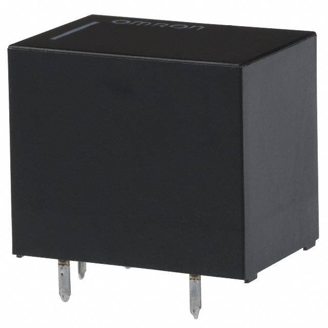
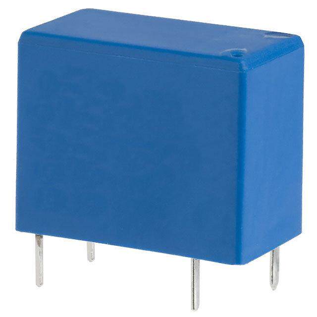
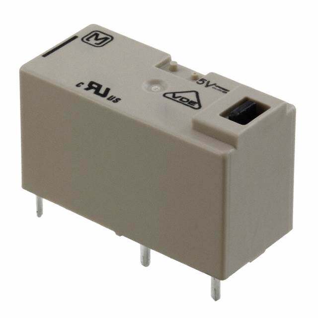
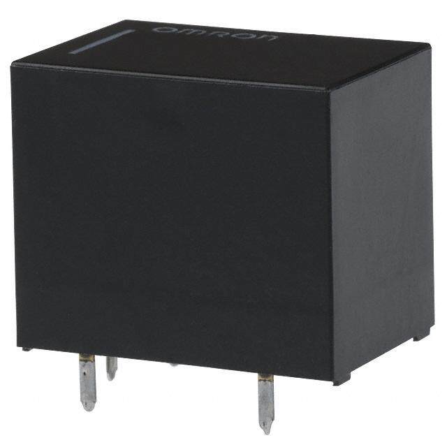
ICGOO电子元器件商城为您提供G5LE-1-VDDC24由Omron Electronics LLC设计生产,在icgoo商城现货销售,并且可以通过原厂、代理商等渠道进行代购。 G5LE-1-VDDC24价格参考。Omron Electronics LLCG5LE-1-VDDC24封装/规格:功率继电器,高于 2 A, 通用 继电器 SPDT(1 Form C) 24VDC 线圈 通孔。您可以下载G5LE-1-VDDC24参考资料、Datasheet数据手册功能说明书,资料中有G5LE-1-VDDC24 详细功能的应用电路图电压和使用方法及教程。
Omron Electronics Inc-EMC Div 生产的功率继电器型号 G5LE-1-VDDC24,属于小型密封继电器系列,额定电流为 5 A(高于 2 A),适用于多种工业和商业应用场景。以下是该型号的一些典型应用场景:

 1. 工业自动化设备
   - PLC 控制系统:用于控制大功率负载,例如电机、电磁阀或加热器。
   - 生产线开关控制:在流水线中切换高电流设备,如输送带电机或气动执行器。
   - 传感器信号放大:将低功率信号转换为高功率输出,驱动外部设备。

 2. 家用电器
   - 空调压缩机控制:用于启动和停止压缩机,确保高效运行。
   - 洗衣机/干衣机功能切换:控制不同模式下的电机或加热元件。
   - 电热水器加热控制:通过继电器实现加热元件的通断。

 3. 汽车电子
   - 车载设备电源管理:例如控制车灯、雨刷电机或电动座椅的供电。
   - 新能源汽车充电模块:用于切换充电电路中的高电流路径。

 4. 医疗设备
   - 诊断仪器:控制内部高功率组件,例如加热模块或风扇。
   - 治疗设备:用于切换高压或高电流负载,如激光器或超声波发生器。

 5. 通信设备
   - 基站电源管理:在电信基站中切换备用电池或主电源。
   - 网络服务器散热系统:控制风扇或其他冷却设备的运行。

 6. 照明系统
   - LED 照明控制:用于大型 LED 灯具的开关控制。
   - 景观灯或广告牌灯控制:根据时间或环境光线变化自动开启或关闭。

 7. 安防系统
   - 监控摄像头电源管理:控制摄像头的供电或加热器以适应低温环境。
   - 门禁系统:用于驱动电磁锁或其他高功率设备。

 特点与优势
- 高可靠性:采用 Omron 的高品质制造工艺,适合频繁切换的场景。
- 小型化设计:节省安装空间,便于集成到紧凑型设备中。
- 宽电压范围:支持 DC 24V 驱动,适配多种控制系统。

综上所述,G5LE-1-VDDC24 型号的功率继电器广泛应用于需要高电流切换的各种领域,能够满足工业、家用、汽车及医疗等行业的多样化需求。
| 参数 | 数值 |
| 产品目录 | |
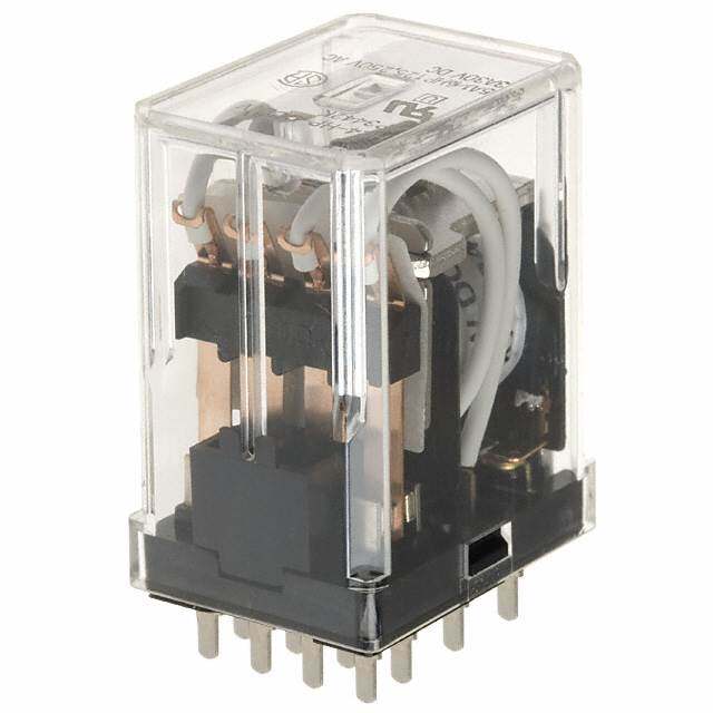
| 描述 | RELAY GEN PURPOSE SPDT 10A 24V |
| 产品分类 | |
| 品牌 | Omron Electronics Inc-EMC Div |
| 数据手册 | |
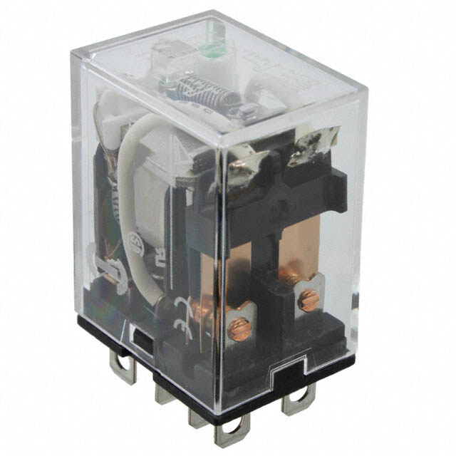
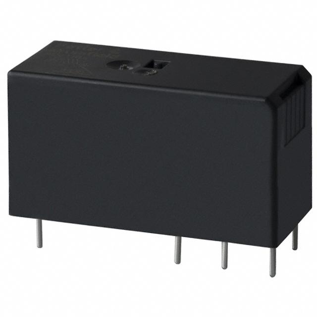
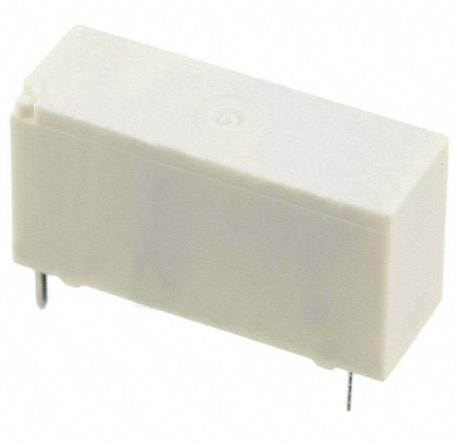
| 产品图片 |
|
| 产品型号 | G5LE-1-VDDC24 |
| rohs | 无铅 / 符合限制有害物质指令(RoHS)规范要求 |
| 产品系列 | G5LE |
| 产品目录绘图 |
|
| 关闭电压(最小值) | 2.4 VDC |
| 其它名称 | G5LE-1-VDDC24-ND |
| 其它有关文件 | |
| 包装 | 散装 |
| 安装类型 | 通孔 |
| 导通电压(最大值) | 18 VDC |
| 工作时间 | 10ms |
| 工作温度 | -40°C ~ 85°C |
| 开关电压 | 250VAC,125VDC - 最小值 |
| 标准包装 | 100 |
| 特性 | 绝缘 - B 级,密封式 - 焊剂防护 |
| 端子类型 | PC 引脚 |
| 线圈功率 | 400 mW |
| 线圈电压 | 24VDC |
| 线圈电流 | 16.7mA |
| 线圈电阻 | 1.44 千欧 |
| 线圈类型 | 无锁存 |
| 继电器类型 | 通用 |
| 触头外形 | SPDT(1 C 型) |
| 触头材料 | 银锡氧化物(AgSnO) |
| 释放时间 | 5ms |
| 额定接触(电流) | 10A |

_SPDT%20Footprint.jpg)


.jpg)

PDF Datasheet 数据手册内容提取
G5LE PCB Power Relay Cubic, Single-pole 10A Power Relay •Ideal for a wide variety of applications such as home appliances, OA equipments, vending machines, etc. •Ambient Operating Temperature 85°C •UL class-B coil insulation for standard model. •UL, CSA, EN standards approved and conforms to Electrical Appliance and Material Safety Law (300 V max.). RoHS Compliant ■Model Number Legend ■Application Examples G5LE-@@@ •Home appliances — — — 1 2 3 •OA equipments 1. Number of Poles 3. Enclosure rating •Vending machines 1: 1-pole None:Flux protection 4: Fully sealed G 2. Contact Form 5 None:SPDT (1c) L A: SPST-NO (1a) E ■Ordering Information ■Characteristics Enclosure rating Flux protection Fully sealed Contact resistance *1 100 mΩ max. Minimun Terminal Rated coil Rated coil Operate time 10 ms max. Model Model packing unit Shape Classification Contact form voltage voltage Release time 5 ms max. 5 VDC 5 VDC Insulation resistance *2 100 MΩ min. SPDT (1c) G5LE-1 12 VDC G5LE-14 12 VDC Between 2,000 VAC, 50/60 Hz PCB 24 VDC 24 VDC 100 pcs/ coil and Standard for 1 min terminals 5 VDC 5 VDC tray contacts Dielectric SPST-NO (1a) G5LE-1A 12 VDC G5LE-1A4 12 VDC strength Between 24 VDC 24 VDC contacts of 750 VAC, 50/60 Hz the same for 1 min Note.When ordering, add the rated coil voltage to the model number. polarity Example: G5LE-1 DC5 Rated coil voltage Impulse between withstand coil and 4,500 V (1.2×50 μs) However, the notation of the coil voltage on the product case as well as on the packing will be marked voltage contacts as @@ VDC. 10 to 55 to 10 Hz, ■Ratings Destruction 0.75 mm single amplitude Vibration (1.5 mm double amplitude) ●Coil resistance 10 to 55 to 10 Hz, Malfunction 0.75 mm single amplitude Must operate Must release Max. (1.5 mm double amplitude) Rated Coil Power Rated voltage voltage voltage Shock Destruction 1,000 m/s2 current resistance consumption voltage (mA) (Ω) (V) (V) (V) (mW) resistance Malfunction 100 m/s2 % of rated voltage 10,000,000 operations min. Mechanical 5 VDC 79.4 63 (at 18,000 operations/hr) 170% Durability 12 VDC 33.3 360 75% max. 10% min. Approx. 400 100,000 operations min. at 23°C Electrical 24 VDC 16.7 1,440 (at 1,800 operations/hr) Note 1.The rated current and coil resistance are measured at a coil temperature of 23°C with a tolerance Failure rate (P level) 100 mA at 5 VDC of ±10%. (reference value) *3 2.The operating characteristics are measured at a coil temperature of 23°C. -25°C to 85°C Ambient operating 3.The “Max. voltage” is the maximum voltage that can be applied to the relay coil. (with no icing or temperature condensation) ●Contacts Ambient operating 35% to 85% humidity Item Load Resistive load Inductive lead (cosφ = 0.4) Weight Approx. 12 g Contact type Single Note.The data given above are initial values Contact material Ag-alloy (Cd free) *1. Measurement conditions: 5 VDC, 1 A, voltage Rated load 10 A at 120 VAC; 8 A at 30 VDC 5 A at 120 VAC; 4 A at 30 VDC drop method. Rated carry current 10 A *2. Measurement conditions: The insulation Max. switching voltage 250 VAC, 125 VDC (30 VDC when UL/CSA standard is applied) resistance was measured with a 500 VDC Max. switching current 10 A 5 A megohmmeter at the same locations as the dielectric strength was measured. *3. This value was measured at a switching frequency of 120 operations/min. 1
G5LE PCB Power Relay ■Engineering Data ●Maximum Switching Capacity ●Durability ●Ambient Temperature vs. Maximum Coil Voltage Switching current (A)531000753 AloACa(cCd roe sinsφids (cid:32)uti cv0te.i4ve) 4Durability (x10 operations)531000753000000 3re0s iVsDtivCe load1re2s0is VtivAeC l oad Maximum coil voltage (%)211086000 140 1 DC resistive 10 0.7 load 7 120 0.5 5 0.3 3 250 VAC resistive load 100 120 VAC inductive (cosφ = 0.4) 0 10 30 50 100 500 1,000 0 2 4 6 8 10 12 −025 20 30 40 50 60 70 80 90 100 Switching voltage (V) Switching current (V) Ambient temperature (°C) Note.The maximum coil voltage refers to the maximum value in a varying range of operating power voltage, not a continuous voltage. ●Shock Malfunction NO contact Y 1,000 NC contact G 1,000 1,000 5 X 500 Z’ L E Z Y Y’ Z 500 X’ X’ 1,000 1,000 Z’ X 1,000 Y’ Unit: m/s2 Shock direction Number of Relays:5 pcs Test Conditions: Shock was applied 3 times in each direction with and without excitation and the level at which the shock caused malfunction was measured. Rating: 100 m/s2 ■Dimensions G5LE-1 (SPDT contact) PCB Mounting Holes Terminal Arrangement/ G5LE-1A (SPST-NO contact) (Bottom View) Internal Connections (21.6)* (15.6)* Tolerance: ±0.1 mm unless (Bottom View) 22.5 max. 16.5 max. specified SPDT (1c) SPDT (1c) (18.56)* Five,1.3+ 00.2 dia. holes 19.0 max. (2.25) 2 3 0.5 12 1 3.5 5 4 0.2 1 1.2 0.4 *Average value 12.2 (2.55) 2 (5.75) (2.25) (Indicates average dimensions.) G5LE-14 (SPDT contact) G5LE-1A4 (SPST-NO contact) 22(2.51 .m6)a*x. 16(1.55 .m6)a*x. SPST-NO (1a) SPST-NO (1a) Four,1.3 + 00.2 dia. holes (2.25) 2 3 (18.5)* 19.0 max. 12 1 0.5 5 3.5 12.2 (2.55) 2 (5.75) (2.25) (Indicates average dimensions.) 0.2 1 1.2 0.4 *Average value Note. Orientation marks are indicated as follows: 2
G5LE PCB Power Relay ■Approved Standards UL Recognized: (File No. E41643) Coil Number of test Model Contact form Contact ratings ratings operations 10 A, 250 VAC (general use) at 40°C SPDT-NO (1a) 5 to 6,000 G5LE 8 A, 30 VDC SPDT (1c) 24 VDC (resistive load) at 40°C TV-3 (N.O only) 40°C 25,000 CSA Certified: (File No. LR31928) Coil Number of test Model Contact form Contact ratings ratings operations 10 A, 250 VAC (general use) at 40°C SPDT-NO (1a) 5 to 8 A, 30 VDC 6,000 G5LE SPDT (1c) 24 VDC (resistive load) at 40°C TV-3 (N.O only) 40°C 25,000 VDE EN/IEC Certified: (Certificate No. 6850) Coil Number of test Model Contact form Contact ratings ratings operations SPDT-NO (1a) 5, 12, 24 10 A, 250 VAC G5LE SPDT (1c) VDC (cosφ = 1) 85°C 50,000 TÜV EN/IEC Certified: (Certificate No. R50158258) Coil Number of test G Model Contact form Contact ratings ratings operations 5 2.5 A, 250 VAC L (cosφ = 0.4) 85°C 100,000 E SPDT-NO (1a) 5, 12, 24 10 A, 250 VAC G5LE 50,000 SPDT (1c) VDC (resistive load) at 85°C 8 A, 30 VAC 100,000 (resistive load) at 40°C ■Precautions •Please refer to “PCB Relays Common Precautions” for correct use. 3
G5LE PCB Power Relay G 5 L E (cid:129) Application examples provided in this document are for reference only. In actual applications, confirm equipment functions and safety before using the product. (cid:129) Consult your OMRON representative before using the product under conditions which are not described in the manual or applying the product to nuclear control systems, railroad systems, aviation systems, vehicles, combustion systems, medical equipment, amusement machines, safety equipment, and other systems or equipment that may have a serious influence on lives and property if used improperly. Make sure that the ratings and performance characteristics of the product provide a margin of safety for the system or equipment, and be sure to provide the system or equipment with double safety mechanisms. Note: Do not use this document to operate the Unit. OMRON Corporation Electronic and Mechanical Components Company Contact: www.omron.com/ecb Cat. No. K100-E1-07 1116(0207)(O) 4