 Datasheet下载
- 型号: G3VM-61A1
- 制造商: Omron Electronics LLC
- 库位|库存: xxxx|xxxx
- 要求:
| 数量阶梯 | 香港交货 | 国内含税 |
| +xxxx | $xxxx | ¥xxxx |
查看当月历史价格
查看今年历史价格
G3VM-61A1产品简介:
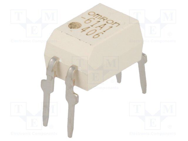
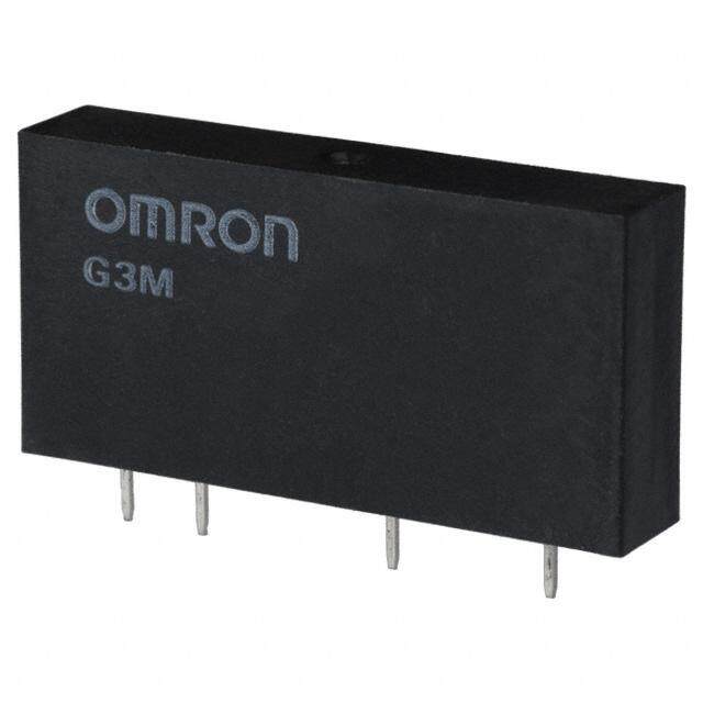
ICGOO电子元器件商城为您提供G3VM-61A1由Omron Electronics LLC设计生产,在icgoo商城现货销售,并且可以通过原厂、代理商等渠道进行代购。 G3VM-61A1价格参考¥13.32-¥24.47。Omron Electronics LLCG3VM-61A1封装/规格:固态继电器, 固体继电器 继电器 SPST-NO(1 Form A) 4-DIP(0.300",7.62mm)。您可以下载G3VM-61A1参考资料、Datasheet数据手册功能说明书,资料中有G3VM-61A1 详细功能的应用电路图电压和使用方法及教程。
欧姆龙电子有限公司(Omron Electronics Inc.)EMC部门生产的固态继电器G3VM-61A1,是一种无触点电子开关器件,适用于多种自动化和工业控制场景。该型号为六路输出固态继电器,具备高可靠性、长寿命和快速响应等特点,广泛应用于以下场景:

1. 工业自动化设备:用于PLC控制系统中,作为执行机构的驱动元件,实现对电机、电磁阀、指示灯等负载的通断控制。

2. 温度控制系统:在温控装置中用于控制加热器或冷却设备的启停,实现精确的温度调节。

3. 测试与测量设备:用于自动测试系统中,实现对被测电路的自动切换与控制。

4. 安防与监控系统:用于视频监控系统或门禁系统的电源管理与设备控制。

5. 医疗设备:用于需要高可靠性和电气隔离的医疗仪器中,如监护仪、诊断设备等。

6. 照明控制系统:用于智能照明系统中,实现对灯具的远程控制与调光功能。

7. 新能源领域:如太阳能逆变器、储能系统中,用于切换不同电路状态或保护系统安全。

G3VM-61A1具备良好的抗干扰能力和电气隔离性能,适合在复杂电磁环境中稳定工作,是现代电子控制系统中理想的开关元件。
| 参数 | 数值 |
| 产品目录 | |
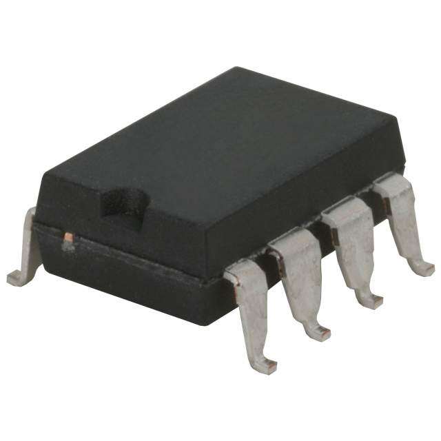
| 描述 | RELAY SSR SPST 60V 500MA 4DIP固态继电器-PCB安装 60V, SPST-NO, DIP4 PCB 500mA 1ohm 130pF |
| 产品分类 | |
| 品牌 | Omron Electronics |
| 产品手册 | |
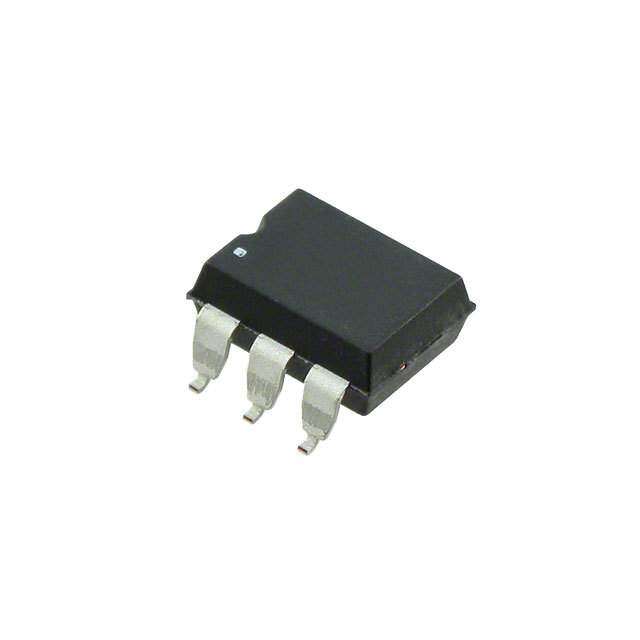
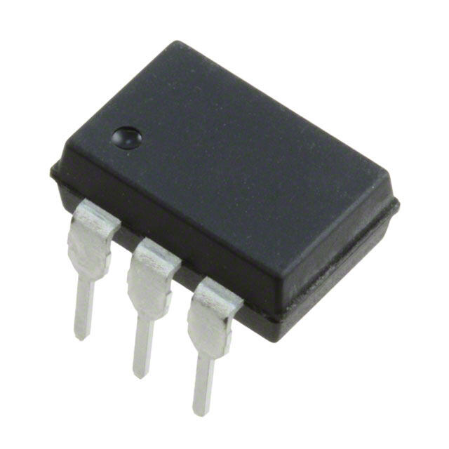
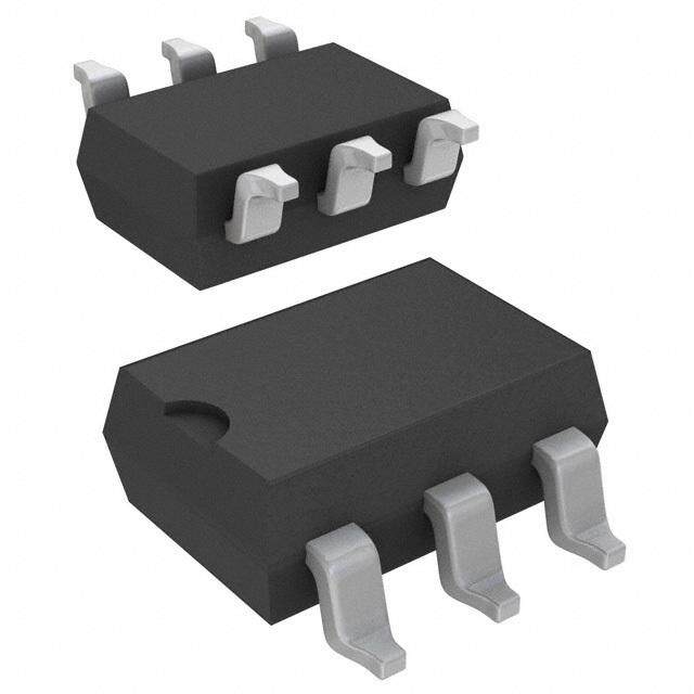
| 产品图片 |
|
| rohs | 符合RoHS无铅 / 符合限制有害物质指令(RoHS)规范要求 |
| 产品系列 | 固态继电器,固态继电器-PCB安装,Omron Electronics G3VM-61A1G3VM |
| mouser_ship_limit | 该产品可能需要其他文件才能进口到中国。 |
| 数据手册 | |
| 产品型号 | G3VM-61A1 |
| 产品 | Power Relays |
| 产品培训模块 | http://www.digikey.cn/PTM/IndividualPTM.page?site=cn&lang=zhs&ptm=25458 |
| 产品目录绘图 |
|
| 产品目录页面 | |
| 产品种类 | 固态继电器-PCB安装 |
| 产品类型 | PCB Mount |
| 供应商器件封装 | 4-DIP |
| 其它名称 | G3VM61A1 |
| 其它有关文件 | |
| 包装 | 管件 |
| 商标 | Omron Electronics |
| 安装类型 | 通孔 |
| 安装风格 | Through Hole |
| 导通电阻 | 2 欧姆 |
| 封装/外壳 | 4-DIP(0.300",7.62mm) |
| 封装/箱体 | DIP-4 |
| 工厂包装数量 | 100 |
| 控制电压范围 | 1 V to 1.3 V |
| 标准包装 | 100 |
| 电压-负载 | 0 ~ 60 V |
| 电压-输入 | 1.15VDC |
| 电路 | SPST-NO(1 A 形) |
| 端子类型 | PC 引脚 |
| 端接类型 | Solder Pin |
| 系列 | G3VM |
| 继电器类型 | |
| 触点形式 | SPST (1 Form A) |
| 负载电压额定值 | 60 V |
| 负载电流 | 500mA |
| 负载电流额定值 | 500 mA |
| 输入电流 | 50 mA |
| 输入转输出绝缘方法 | Optocoupler |
| 输出类型 | AC,DC |
| 输出设备 | MOSFET |
| 零件号别名 | G3VM61A1NC |


.jpg)

- 商务部:美国ITC正式对集成电路等产品启动337调查
- 曝三星4nm工艺存在良率问题 高通将骁龙8 Gen1或转产台积电
- 太阳诱电将投资9.5亿元在常州建新厂生产MLCC 预计2023年完工
- 英特尔发布欧洲新工厂建设计划 深化IDM 2.0 战略
- 台积电先进制程称霸业界 有大客户加持明年业绩稳了
- 达到5530亿美元!SIA预计今年全球半导体销售额将创下新高
- 英特尔拟将自动驾驶子公司Mobileye上市 估值或超500亿美元
- 三星加码芯片和SET,合并消费电子和移动部门,撤换高东真等 CEO
- 三星电子宣布重大人事变动 还合并消费电子和移动部门
- 海关总署:前11个月进口集成电路产品价值2.52万亿元 增长14.8%


PDF Datasheet 数据手册内容提取
G3VM-61A1/D1 MOS FET Relays Compact, General-purpose, Analog switching MOS FET Relays, with Dielectric Strength of 2.5 kVAC between I/O Using Optical Isolation. •Upgraded G3VM-61A/D Series. (cid:127)Switches minute analog signals. (cid:127)Leakage current of 1 µA max. when output relay is open. RoHS compliant Note: The actual product is marked differently from the image shown here. ■Application Examples ■Terminal Arrangement/Internal Connections (cid:127)Test & Measurement equipment (cid:127)Security equipment 4 3 Mold pin mark * (cid:127)Amusement equipment OMRON logo Model name Pin 1 mark 932 LOT.NO. 1 2 Note:The actual product is marked differently from the image shown here. *The indentation in the corner diagonally opposite from the pin 1 mark is from a pin on the mold. ■List of Models Load voltage Minimum package quantity Package type Contact form Terminals Model (peak value) * Number per tube Number per tape and reel PCB Terminals G3VM-61A1 1a 100 - DIP4 60 V G3VM-61D1 (SPST-NO) Surface-mounting Terminals G3VM-61D1(TR) - 1,500 *The AC peak and DC value are given for the load voltage. ■Absolute Maximum Ratings (Ta = 25°C) Item Symbol Rating Unit Measurement conditions LED forward current IF 50 mA put RLEepDe ftoitrivwea prde acku rLrEeDnt f roerdwuacrdti ocnu rrraetnet ∆IIFF/P°C −01. 5 mAA/° C 1T0a0 ≥ µ 2s5 p°Cul ses, 100 pps n I LED reverse voltage VR 5 V Connection temperature TJ 125 °C Load voltage (AC peak/DC) VOFF 60 V put Continuous load current (AC peak/DC) IO 500 mA Out ON current reduction rate ∆IO/°C −5.0 mA/°C Ta ≥ 25°C Connection temperature TJ 125 °C Dielectric strength between I/O (See note 1.) VI-O 2500 Vrms AC for 1 min Note: 1. The dielectric strength between the input and Ambient operating temperature Ta −40 to +85 °C With no icing or condensation output was checked by applying voltage Ambient storage temperature Tstg −55 to +125 °C With no icing or condensation between all pins as a group on the LED side and Soldering temperature - 260 °C 10 s all pins as a group on the light-receiving side. ■Electrical Characteristics (Ta = 25°C) Item Symbol Minimum Typical Maximum Unit Measurement conditions LED forward voltage VF 1.0 1.15 1.3 V IF = 10 mA Note: 2. Turn-ON and Turn-OFF Times Input RCTraeipgvagecerirst yLe Eb Dceut fworerrweenna rttd e rcmuirnreanlst CIIFRTT --- 13-.06 13-0 mµpAFA VIVO R == = 05 5,0 f0V = m 1A MHz IF 12 43 RL VVDODUT ut Maximum resistance with output ON RON - 1 2 Ω IF = 5 mA, IO = 500 mA utp Current leakage when the relay is open ILEAK - - 1.0 µA VOFF = 60 V O Capacity between terminals COFF - 130 - pF V = 0, f = 1 MHz IF Capacity between I/O terminals CI-O - 0.8 - pF f = 1 MHz, VS = 0 V Insulation resistance between I/O terminals RI-O 1000 - - MΩ VI-O = 500 VDC, ROH ≤ 60% Turn-ON time tON - 0.8 2.0 ms IF = 5 mA, RL = 200 Ω, VOUT 10% 90% Turn-OFF time tOFF - 0.1 0.5 ms VDD = 20 V(See note 2.) tON tOFF 1
G3VM-61A1/D1 MOS FET Relays ■Recommended Operating Conditions Use the G3VM under the following conditions so that the Relay will operate properly. Item Symbol Minimum Typical Maximum Unit Load voltage (AC peak/DC) VDD - - 48 V Operating LED forward current IF 5 7.5 25 mA Continuous load current (AC peak/DC) IO - - 500 mA Ambient operating temperature Ta −20 - 65 °C ■Engineering Data LED forward current vs. Ambient Continuous load current vs. Ambient LED forward current vs. LED forward temperature temperature voltage IF - Ta IO - Ta IF - VF mA) 100 mA) 600 mA)100 Ta = 25°C ED forward current I (F 648000 nuous load current I (O 543000000 ED forward current I (F 31003 L onti 200 L 1 C 20 100 0.3 0 0 0.1 -20 0 20 40 60 80 100 120 -20 0 20 40 60 80 100 120 0.6 0.8 1 1.2 1.4 1.6 1.8 Ambient temperature Ta (°C) Ambient temperature Ta (°C) LED forward voltage VF (V) Continuous load current vs. On-state On-state resistance vs. Ambient Trigger LED forward current vs. voltage temperature Ambient temperature IO - VON RON - Ta IFT - Ta Continuous load current I (mA)O -2462000000000 ITFa = = 5 2m5A°C ΩOn-state resistance R ()ON 3245 IIOF == 55m00AmA er LED forward current I (mA)FT 3245 ItO < = 1 5s00mA g g -400 1 Tri 1 -600 0 0 -0.6 -0.4 -0.2 0 0.2 0.4 0.6 -20 0 20 40 60 80 100 -20 0 20 40 60 80 100 On-state voltage VON (V) Ambient temperature Ta (°C) Ambient temperature Ta (°C) Turn ON, Turn OFF time vs. LED Turn ON, Turn OFF time vs. Ambient Current leakage vs. Ambient forward current temperature temperature tON, tOFF - IF tON, tOFF - Ta ILEAK - Ta µN, Turn OFF time t, t (s)ONOFF 135000350000000000 tOFFRTVaDL D == = 22 20500°VCΩ µN, Turn OFF time t, t (s)ONOFF 31003100000000 ttOONFF Current leakage I (nA)LEAK 310031 VOFF = 60V O O Turn 15000 tON Turn 30 VRDL D= = 2 2000VΩ 0.3 IF = 5mA 30 10 0.1 1 3 5 10 30 50 100 300 -20 0 20 40 60 80 100 -20 0 20 40 60 80 100 LED forward current IF (mA) Ambient temperature Ta (°C) Ambient temperature Ta (°C) ■Safety Precautions (cid:127)Refer to "Common Precautions" for all G3VM models. 2
Appearance/Dimensions DIP4 type ■Appearance DDIIPP ((DDuuaall IInnlliinnee PPaacckkaaggee)) DIP4 Mold pin mark * OMRON logo Model name Pin 1 mark 932 LOT.NO. Note: The actual product is marked differently from the image shown here. * The indentation in the corner diagonally opposite from the pin 1 mark is from a pin on the mold. ■Dimensions (Unit:mm) PCB Terminals Surface-mounting Terminals PCB Dimensions (BOTTOM VIEW) Weight: 0.25 g Weight: 0.25 g Four, 0.8-dia. holes 2.54 (0.61) 2.54 4.58±0.25 4.58±0.25 (0.61) 6.4±0.25 6.4±0.25 (1.52) (1.52) 7.62±0.25 Actual Mounting Pad Dimensions 0.8±0.25 7.62±0.25 (Recommended Value, TOP VIEW) 3.65+-00..2155 0.25+-00..015 3.65+-00..2155 4.0+-00..225 2.54 1.0 min. 2.5 min. 01..52±±00..115 7.85 to 8.80 1.2±0.15 1.0 min. 8.3 to 8.8 2.54±0.25 2.54±0.25 10.0 max. Note:The actual product is marked differently from the 1.3 1.5 image shown here. • Application examples provided in this document are for reference only. In actual applications, confirm equipment functions and safety before using the product. • Consult your OMRON representative before using the product under conditions which are not described in the manual or applying the product to nuclear control systems, railroad systems, aviation systems, vehicles, combustion systems, medical equipment, amusement machines, safety equipment, and other systems or equipment that may have a serious influence on lives and property if used improperly. Make sure that the ratings and performance characteristics of the product provide a margin of safety for the system or equipment, and be sure to provide the system or equipment with double safety mechanisms. Note: Do not use this document to operate the Unit. OMRON Corporation ELECTRONIC AND MECHANICAL COMPONENTS COMPANY Contact: www.omron.com/ecb Cat. No. K143-E1-01 0412(0412)(O)
Mouser Electronics Authorized Distributor Click to View Pricing, Inventory, Delivery & Lifecycle Information: O mron: G3VM-61A1