 Datasheet下载
- 型号: FSS1500NGT
- 制造商: Honeywell Solid State Electronics
- 库位|库存: xxxx|xxxx
- 要求:
| 数量阶梯 | 香港交货 | 国内含税 |
| +xxxx | $xxxx | ¥xxxx |
查看当月历史价格
查看今年历史价格
FSS1500NGT产品简介:
ICGOO电子元器件商城为您提供FSS1500NGT由Honeywell Solid State Electronics设计生产,在icgoo商城现货销售,并且可以通过原厂、代理商等渠道进行代购。 FSS1500NGT价格参考¥472.87-¥604.86。Honeywell Solid State ElectronicsFSS1500NGT封装/规格:力传感器, Resistive Force Sensor 1.5kgf (3.3lbs)。您可以下载FSS1500NGT参考资料、Datasheet数据手册功能说明书,资料中有FSS1500NGT 详细功能的应用电路图电压和使用方法及教程。
Honeywell Sensing and Productivity Solutions的力传感器型号FSS1500NGT是一款高精度、低量程的拉压式力传感器,其应用场景广泛,适用于多种工业和商业领域。以下是该型号的主要应用场景:

 1. 工业自动化
   - 在工业机器人中用于检测抓取物体时的力度,确保对易碎或精密部件的操作安全。
   - 应用于装配线上的张力测量,例如电缆、带材或纺织品的生产过程中,监测材料的张力是否在合理范围内。

 2. 医疗设备
   - 用于医疗器械中的力反馈系统,如手术机器人、康复设备等,精确控制操作力度,保护患者安全。
   - 在注射器、输液泵等设备中,监测液体流动时的压力变化。

 3. 实验室与测试设备
   - 在材料测试中,用于测量样品的拉伸、压缩或弯曲力,评估材料的力学性能。
   - 作为实验仪器的一部分,提供高精度的力值数据采集功能。

 4. 消费电子
   - 用于触控笔、电子秤或其他需要力感应的消费电子产品中,实现人机交互的精准控制。
   - 在智能家居设备中,监测门窗开关时的力值,防止夹伤风险。

 5. 航空航天与汽车
   - 在航空航天领域,用于监测飞行器零部件的受力情况,确保结构安全。
   - 在汽车制造中,用于刹车系统、悬挂系统或座椅调节装置的力反馈检测。

 6. 包装与物流
   - 在包装机械中,用于监测封口、打包或贴标过程中的力值,确保包装质量。
   - 在物流分拣系统中,用于称重或检测物品放置时的冲击力。

 7. 运动与健身设备
   - 在健身器材中,用于监测用户施加的力,为用户提供实时反馈和数据分析。
   - 在步态分析或康复训练设备中,记录人体运动时的力变化。

 总结
FSS1500NGT凭借其高精度、小尺寸和可靠性,适合需要精确力测量的各种场景。无论是工业生产、医疗健康还是日常消费品,这款传感器都能满足不同领域的应用需求,帮助提升系统的性能和安全性。
| 参数 | 数值 |
| 产品目录 | |
| 描述 | SENSOR FORCE 1500G力传感器与测压元件 14.7 N Force Low Deflection |
| 产品分类 | |
| 品牌 | Honeywell |
| 产品手册 | http://sensing.honeywell.com/index.php?ci_id=50163 |
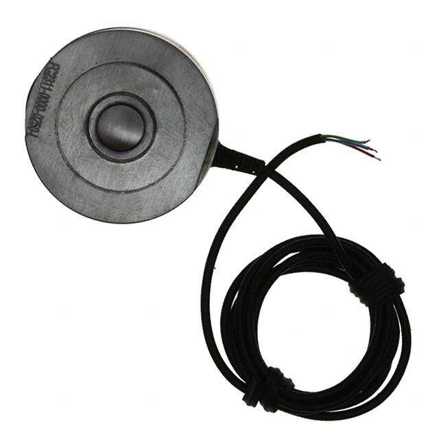
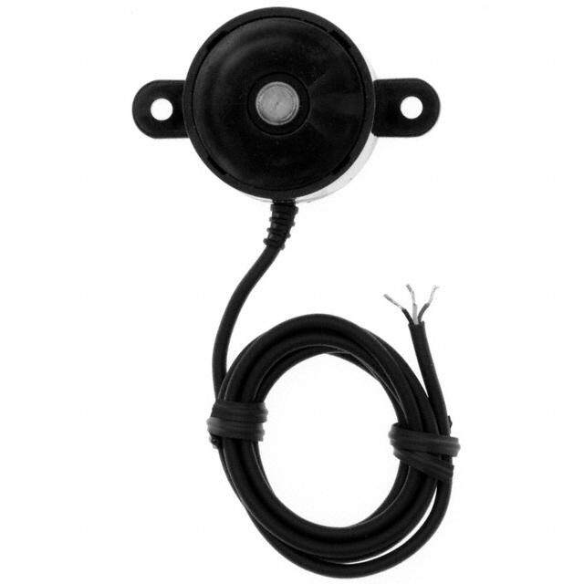
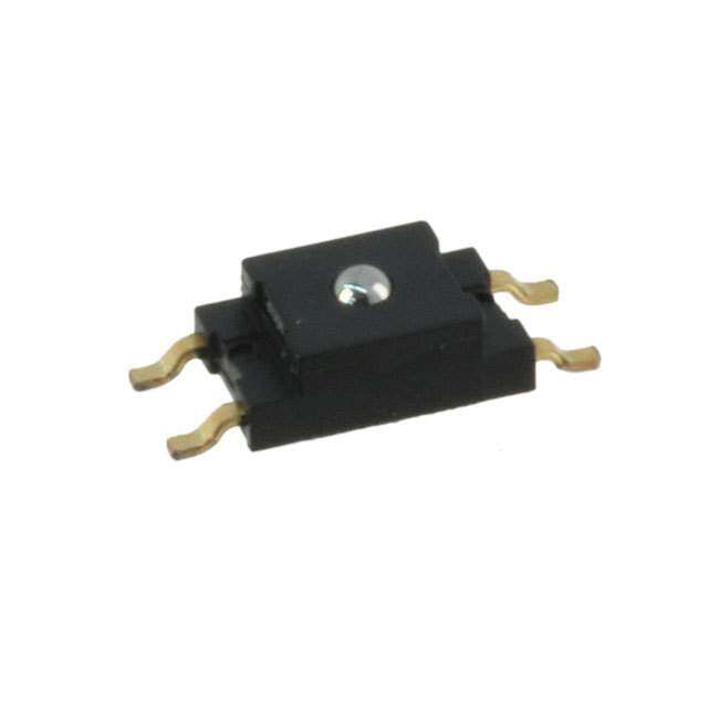
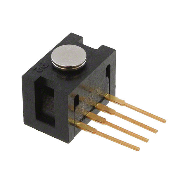
| 产品图片 |
|
| rohs | 符合RoHS无铅 / 符合限制有害物质指令(RoHS)规范要求 |
| 产品系列 | 力传感器与测压元件,Honeywell FSS1500NGTFSS |
| 数据手册 | http://sensing.honeywell.com/index.php/ci_id/44994/la_id/1/document/1/re_id/0http://sensing.honeywell.com/index.php/ci_id/44997/la_id/1/document/1/re_id/0 |
| 产品型号 | FSS1500NGT |
| PCN设计/规格 | |
| 产品目录页面 | |
| 产品种类 | 力传感器与测压元件 |
| 传感器类型 | Force Sensor |
| 作用力 | 1.5kgf(3.3磅) |
| 其它名称 | 480-3308-5 |
| 准确性 | 0.5 % |
| 商标 | Honeywell |
| 安装风格 | SMD/SMT |
| 工作力 | 1.5 kgf |
| 工作温度 | -40°C ~ 85°C |
| 工作电源电压 | 5 V |
| 工厂包装数量 | 100 |
| 最大工作温度 | + 85 C |
| 最小工作温度 | - 40 C |
| 标准包装 | 100 |
| 电压-电源 | 3 V ~ 6 V |
| 电源电压-最大 | 6 V |
| 电源电压-最小 | 3 V |
| 电源电流 | 1.2 mA |
| 系列 | FSS |
| 致动器样式/尺寸 | 圆形,1.98mm |
| 致动器类型 | 滚珠 |
| 输出 | 180mV |
| 输出类型 | Analog |


- 商务部:美国ITC正式对集成电路等产品启动337调查
- 曝三星4nm工艺存在良率问题 高通将骁龙8 Gen1或转产台积电
- 太阳诱电将投资9.5亿元在常州建新厂生产MLCC 预计2023年完工
- 英特尔发布欧洲新工厂建设计划 深化IDM 2.0 战略
- 台积电先进制程称霸业界 有大客户加持明年业绩稳了
- 达到5530亿美元!SIA预计今年全球半导体销售额将创下新高
- 英特尔拟将自动驾驶子公司Mobileye上市 估值或超500亿美元
- 三星加码芯片和SET,合并消费电子和移动部门,撤换高东真等 CEO
- 三星电子宣布重大人事变动 还合并消费电子和移动部门
- 海关总署:前11个月进口集成电路产品价值2.52万亿元 增长14.8%
PDF Datasheet 数据手册内容提取
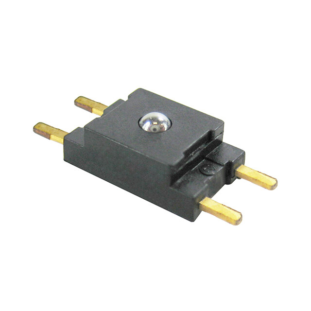
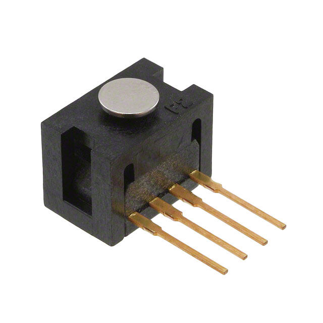
FSS Series Low Profile Force Sensor DESCRIPTION The FSS Series Force Sensor provides precise, reliable force The sensor package design incorporates patented modular sensing performance in a compact, commercial-grade package construction. The use of innovative elastomeric technology and at a cost effective price. The sensor features a proven sensing engineered molded plastics results in overforce capacities of technology that uses a specialized piezoresistive, up to three times the rated force. The stainless steel ball micromachined silicon sensing element. The low power, provides excellent mechanical stability and is adaptable to a unamplified, uncompensated Wheatstone bridge circuit design variety of applications. provides inherently stable mV outputs over the force range. The FSS Series Sensor delivered 20 million operations in Force sensors operate on the principle that the resistance of Mean Cycles to Failure (MCTF) reliability testing at 50°C silicon-implanted piezoresistors will increase when the [122°F]. This test determines the number of possible sensor resistors flex under any applied force. The sensor concentrates operations at full scale until failure. force from the application, through the stainless steel ball, directly to the silicon-sensing element. The amount of resistance changes in proportion to the amount of force being applied. This change in circuit resistance results in a corresponding mV output level change. FEATURES AND BENEFITS POTENTIAL APPLICATIONS RoHS-compliant materials meet Directive 2002/95/EC Medical allows use in industries requiring regulation compliance Infusion pumps Low deflection (approx. 30 µm typical at full scale) helps Ambulatory non-invasive pumps reduce measurement error Direct mechanical coupling of the actuation ball to the Occlusion detection sense element reduces coupling errors and keeps Kidney dialysis machines mechanical hysteresis to a minimum Enteral pumps Product rating of 20 million MCTF at 25 °C [77 °F], subject to application variation, provides for consistent output over Industrial time and reduces repairs or replacements Small size minimizes space on the printed circuit board Load and compression sensing (PCB) Variable tension control Provides enhanced sensitivity without compromising Robotic end-effectors signal integrity, resulting in low system noise and reducing Wire bonding equipment measurement errors Electrically ratiometric output accommodates supply voltage variations, leading to low ratiometricity error Low voltage supply allows for use in many battery powered applications High resistance to electrostatic discharge (ESD) meets ESD Sensitivity Classification Level 3B (8 KV), reducing special handling during assembly Sensor output has low sensitivity to many mounting stresses
FSS Series Table 1. Performance Characteristics (At 10 ±0.01 Vdc, 25 °C [77 °F].)1 FSS005WNSX FSS010WNSX FSS015WNSX FSS020WNSX Characteristic Unit Min. Typ. Max. Min. Typ. Max. Min. Typ. Max. Min. Typ. Max. Force sensing range N 0 to 5 0 to 10 0 to 15 0 to 20 Excitation2 Vdc 3.3 10 12.5 3.3 10 12.5 3.3 10 12.5 3.3 10 12.5 Null offset3 mV -30 0 +30 -30 0 +30 -30 0 +30 -30 0 +30 Null shift4 mV ±0.5 ±0.5 ±0.5 ±0.5 (25 to 0°, 25 to 50° C) Span5 mV 330 360 390 330 360 390 330 360 390 330 360 390 Linearity (BFSL)6 % span ±0.5 - - ±0.5 - - ±0.5 - - ±0.5 - Sensitivity7 mV/V/N 6.6 7.2 7.8 3.3 3.6 3.9 2.2 2.4 2.6 1.65 1.8 1.95 Sensitivity shift8 % span ±5.0 ±5.0 ±5.0 ±5.0 (25 °C to 0°, 25 °C to 50 °C) Repeatability9 % span ±0.2 ±0.2 ±0.2 ±0.2 Response time ms 0.1 0.5 0.1 0.5 0.1 0.5 0.1 0.5 (10 %FS to 90 %FS) Input resistance kΩ 4.0 5.0 6.0 4.0 5.0 6.0 4.0 5.0 6.0 4.0 5.0 6.0 Output resistance kΩ 4.0 5.0 6.0 4.0 5.0 6.0 4.0 5.0 6.0 4.0 5.0 6.0 Plunger deflection µm 26 28 33 39 Overforce10 N 15 30 45 60 Notes: 1. All force-related specifications are established using dead weight or compliant force. CAUTION 2. The range of voltage excitation which can be supplied to the product to produce an output which is proportional to force but due to ratiometricity errors may not remain within the specified performance limits. EXCEEDING Non-compensated force sensors, excited by constant current (1.5 mA) instead of voltage, exhibit partial temperature compensation of span. PRODUCT 3. The output signal obtained when the zero force is applied to the sensor. Also known as "null" or "zero". OVERFORCE RATING 4. The change in the null resulting from a change in temperature. It is not a predictable error as it can shift up and down from unit to unit. Change in temperature causes the entire output curve to shift up or down along Ensure the overforce the voltage axis. ratings given in Table 5. The algebraic difference between output signals measured at the upper and lower limits of the operating force range. Also known as "full scale output" or simply "span". 1 are not exceeded 6. The maximum deviation of product output from a straight line fitted to output measured over the operating during any phase of force range. The straight line through a set of points which minimizes the sum of the square of the deviations of each of the points from the straight line. sensor assembly to 7. The ratio of output signal change to the corresponding input force change. Sensitivity is determined by the board, as well as computing the ratio of span to the specified operating force range multiplied by the supply voltage being used. during the use of the 8. The maximum deviation in sensitivity due to changes in temperature over the operating temperature sensor in the range, relative to sensitivity measured at 25 °C. 9. The maximum difference between output readings when the same force is applied consecutively, under application. the same operating conditions, with force approaching from the same direction within the operating Failure to comply with force range. 10. The maximum force which may safely be applied to the product for it to remain in specification once force is these instructions may returned to the operating force range. Exposure to higher forces may cause permanent damage to the result in product product. Unless otherwise specified, this applies to all temperatures within the operating temperature range. damage. Table 2. Environmental Specifications Characteristic Parameter Operating temperature1 -40 °C to 85 °C [-40 °F to 185 °F] Shock qualification tested to 150 g Vibration qualification tested to 0 to 2 kHz, 20 g sine MCTF (Mean Cycles To Failure)2 20 million at 25 °C [77 °F] Output ratiometric within supply range Notes: 1. The temperature range over which the product may safely be exposed without excitation or force applied. Under these conditions the product will remain in specification after excursion to any temperatures in this range. Exposure to temperatures beyond this range may cause permanent damage to the product. 2. MCTF is a basic measure of reliability for a non-repairable device. It is the mean number of cycles to maximum operating force over which a sensor can be expected to operate until failure. The mean value is determined statistically from a probability distribution for failures based upon test data. MCTF may vary depending on the specific application in which a sensor is utilized. 2 sensing.honeywell.com
Low Profile Force Sensor Table 3. Absolute Maximum Ratings1 Characteristic Parameter Storage temperature2 -40 °C to 100 °C [-40 °F to 212 °F] Solderability3 10 s at 260 °C [500 °F] ESD Meets ESD Sensitivity Classification Level 3B Notes: 1. Absolute maximum ratings are the extreme limits that the product can withstand without damage to the product. 2. The temperature range over which the product may safely be exposed without excitation or force applied. Under these conditions, the product will remain in the specification after excursions to any temperature in this range. Exposure to temperatures beyond this range may cause permanent damage to the product. 3. The maximum temperature and time to which the product may be exposed for processing of solder electrical connections. Figure 1. Excitation Schematic (Excitation 5 Vdc Typ., 6 Vdc max.) 1. Circled numbers refer to sensor terminals (pins). 1 Pin 1 = Supply Vs (+), Pin 2 = Output Vo (+), Pin 3 = Ground Vg (-), Pin 4 = Output Vo (-) 2. The force sensor may be powered by voltage or current. Maximum supply voltage is + not to exceed 6 V. Maximum supply current is not to exceed 1.2 mA. Power is Vs- 2 +Vo- 4 applied across Pin 1 and Pin 3. 3. The sensor output should be measured as a differential voltage across Pin 2 and Pin 4 (Vo = Vo(+)-Vo(-)). The output is ratiometric to the supply voltage. 3 Shifts in supply voltage will cause shifts in output. Neither Pin 2 nor Pin 4 should be tied to ground or voltage supply. Figure 2. Sensor Mounting Dimensions (For reference only: mm/[in].) FSS005WNSX, FSS010WNSX, FSS015WNSX, FSS020WNSX Force Sensing Ball (Actuator) Range Height 0 N to 5 N 0.375 ±0.10 mm [0.0148 ±0.0039 in] 0 N to 10 N 0.452 ±0.10 mm [0. 0178 ±0.0039 in] 0 N to 15 N 0.504 ±0.10 mm [0.01984 ±0.0039 in] 0 N to 20 N 0.562 ±0.10 mm [0.0221 ±0.0039 in] Figure 3. Packaging Dimensions (For reference only.) Short Tube: 43,9 mm [1.73 Tape and Reel (mm) 1. Pocket position relative to sprocket in] long, 5 units/tube hole measured as Standard Tube: 584 mm true position of [22.99 in] long, 100 units/ pocket, not pocket tube hole. 2. 10 sprocket hole pitch cumulative tolerance is ±0.2 mm. Camber is in compliance with EIA 481. Ao and Bo are calculated on a plane at a distance “R” above the bottom of the pocket. Honeywell Sensing and Control 3
Order Guide Catalog Listing Description FSS005WNSB FSS Series Low Profile Force Sensor, 0 N to 5 N force range, short tube packaging FSS005WNSR FSS Series Low Profile Force Sensor, 0 N to 5 N force range, tape and reel packaging FSS005WNST FSS Series Low Profile Force Sensor, 0 N to 5 N force range, standard tube packaging FSS010WNSB FSS Series Low Profile Force Sensor, 0 N to 10 N force range, short tube packaging FSS010WNSR FSS Series Low Profile Force Sensor, 0 N to 10 N force range, tape and reel packaging FSS010WNST FSS Series Low Profile Force Sensor, 0 N to 10 N force range, standard tube packaging FSS015WNSB FSS Series Low Profile Force Sensor, 0 N to 15 N force range, short tube packaging FSS015WNSR FSS Series Low Profile Force Sensor, 0 N to 15 N force range, tape and reel packaging FSS015WNST FSS Series Low Profile Force Sensor, 0 N to 15 N force range, standard tube packaging FSS020WNSB FSS Series Low Profile Force Sensor, 0 N to 20 N force range, short tube packaging FSS020WNSR FSS Series Low Profile Force Sensor, 0 N to 20 N force range, tape and reel packaging FSS020WNST FSS Series Low Profile Force Sensor, 0 N to 20 N force range, standard tube packaging WARNING WARNING MISUSE OF DOCUMENTATION PERSONAL INJURY The information presented in this product sheet is for DO NOT USE these products as safety or emergency stop reference only. Do not use this document as a product devices or in any other application where failure of the installation guide. product could result in personal injury. Complete installation, operation, and maintenance Failure to comply with these instructions could result information is provided in the instructions supplied with in death or serious injury. each product. Failure to comply with these instructions could result in SALES AND SERVICE death or serious injury. Honeywell serves its customers through a worldwide network of sales offices, representatives and distributors. For WARRANTY/REMEDY application assistance, current specifications, pricing or name Honeywell warrants goods of its manufacture as being free of of the nearest Authorized Distributor, contact your local sales defective materials and faulty workmanship. Honeywell’s office or: standard product warranty applies unless agreed to otherwise by Honeywell in writing; please refer to your order E-mail: info.sc@honeywell.com acknowledgement or consult your local sales office for specific Internet: sensing.honeywell.com warranty details. If warranted goods are returned to Honeywell Phone and Fax: during the period of coverage, Honeywell will repair or replace, Asia Pacific +65 6355-2828 at its option, without charge those items it finds defective. The +65 6445-3033 Fax foregoing is buyer’s sole remedy and is in lieu of all other Europe +44 (0) 1698 481481 warranties, expressed or implied, including those of +44 (0) 1698 481676 Fax merchantability and fitness for a particular purpose. In no Latin America +1-305-805-8188 event shall Honeywell be liable for consequential, special, +1-305-883-8257 Fax or indirect damages. USA/Canada +1-800-537-6945 +1-815-235-6847 While we provide application assistance personally, through +1-815-235-6545 Fax our literature and the Honeywell web site, it is up to the customer to determine the suitability of the product in the application. Specifications may change without notice. The information we supply is believed to be accurate and reliable as of this printing. However, we assume no responsibility for its use. Sensing and Control Honeywell 1985 Douglas Drive North Golden Valley, MN 55422 080809-2-EN February 2013 sensing.honeywell.com © 2013 Honeywell International Inc. All rights reserved.
Mouser Electronics Authorized Distributor Click to View Pricing, Inventory, Delivery & Lifecycle Information: H oneywell: FSS1500NSR FSS1500NST FSS1500NGT FSS1500NGR