 Datasheet下载
- 型号: FLT007A0-SRZ
- 制造商: Lineage Power
- 库位|库存: xxxx|xxxx
- 要求:
| 数量阶梯 | 香港交货 | 国内含税 |
| +xxxx | $xxxx | ¥xxxx |
查看当月历史价格
查看今年历史价格
FLT007A0-SRZ产品简介:
ICGOO电子元器件商城为您提供FLT007A0-SRZ由Lineage Power设计生产,在icgoo商城现货销售,并且可以通过原厂、代理商等渠道进行代购。 FLT007A0-SRZ价格参考¥80.13-¥137.45。Lineage PowerFLT007A0-SRZ封装/规格:电力线滤波器模块, 。您可以下载FLT007A0-SRZ参考资料、Datasheet数据手册功能说明书,资料中有FLT007A0-SRZ 详细功能的应用电路图电压和使用方法及教程。
GE Critical Power品牌的FLT007A0-SRZ型号电力线滤波器模块,主要应用于需要高可靠性和低干扰的电力系统中。以下是其典型应用场景:

1. 数据中心:用于保护关键IT设备和服务器免受电磁干扰(EMI)和射频干扰(RFI)的影响,确保数据处理和存储的稳定性。

2. 医疗设备:为敏感的医疗仪器(如MRI、CT扫描仪等)提供纯净的电源环境,避免外部干扰导致诊断结果不准确。

3. 工业自动化:在工厂自动化控制系统中,减少电机、变频器和其他电气设备产生的噪声对控制系统的影响,提高生产效率和精度。

4. 通信设施:保障通信基站和网络设备的电源质量,防止噪声干扰信号传输,提升通信质量。

5. 实验室和测试环境:为精密测量仪器和实验设备提供稳定的电源输入,确保测试结果的准确性。

6. 航空航天与国防:应用于对电源质量要求极高的军工和航空电子系统中,确保设备在恶劣环境下的正常运行。

FLT007A0-SRZ通过其高效的滤波性能,能够有效抑制电力线上的高频噪声和瞬态电压,从而保护下游设备的安全和稳定运行。它适用于各种对电源质量有严格要求的场景,尤其适合需要持续运行的关键基础设施。
| 参数 | 数值 |
| 产品目录 | |
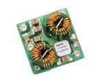
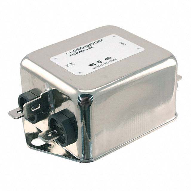
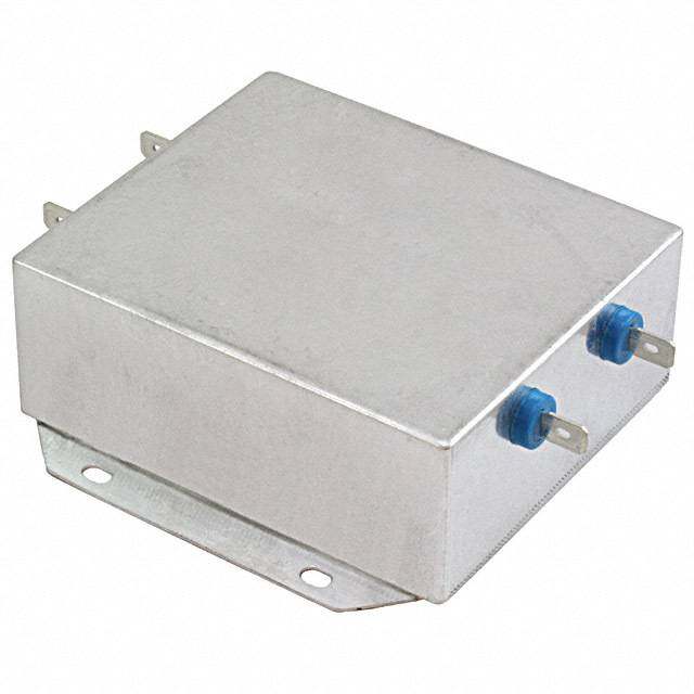
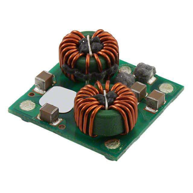
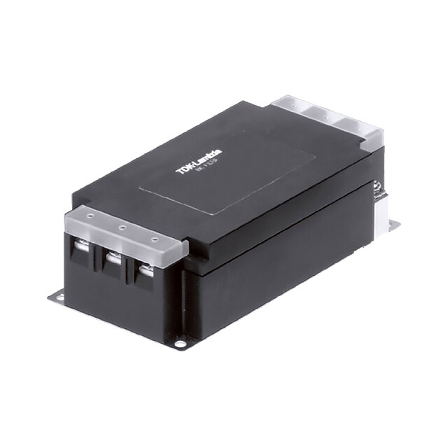
| 描述 | DC FILTER MODULE 75V 7A SMDAC 电源线滤波器 0-75Vin 7A SMT |
| 产品分类 | 线路滤波器交流电源线路滤波器 |
| 品牌 | GE Critical Power |
| 产品手册 | |
| 产品图片 |
|
| rohs | 符合RoHS无铅 / 符合限制有害物质指令(RoHS)规范要求 |
| 产品系列 | GE Critical Power FLT007A0-SRZ- |
| 数据手册 | http://apps.geindustrial.com/publibrary/checkout/FLT007A0?TNR=Data%20SheetsFLT007A0generic |
| 产品型号 | FLT007A0-SRZ |
| 产品目录页面 | |
| 产品种类 | 交流电源线路滤波器 |
| 其它名称 | 555-1154-1 |
| 商标 | GE Critical Power |
| 安装类型 | 表面贴装 |
| 安装风格 | SMD/SMT |
| 封装 | Reel |
| 工作温度 | -40°C ~ 85°C |
| 工厂包装数量 | 140 |
| 应用 | 通用 |
| 标准包装 | 1 |
| 滤波器类型 | 单相 |
| 电压-额定AC | - |
| 电压-额定AC(相对地/相对中性点) | - |
| 电压-额定AC(相对相) | - |
| 电压-额定DC | 75V |
| 电压额定值 | 75 VDC |
| 电流 | 7A |
| 电流额定值 | 7 A |
| 端子类型 | SMD(SMT)接片 |
| 端接类型 | Solder Pad |
| 系列 | FLT |
| 认可 | CE,CSA,UL,VDE |
| 配置 | 两级 |
| 零件号别名 | CC109108701 |
| 频率-工作 | - |


- 商务部:美国ITC正式对集成电路等产品启动337调查
- 曝三星4nm工艺存在良率问题 高通将骁龙8 Gen1或转产台积电
- 太阳诱电将投资9.5亿元在常州建新厂生产MLCC 预计2023年完工
- 英特尔发布欧洲新工厂建设计划 深化IDM 2.0 战略
- 台积电先进制程称霸业界 有大客户加持明年业绩稳了
- 达到5530亿美元!SIA预计今年全球半导体销售额将创下新高
- 英特尔拟将自动驾驶子公司Mobileye上市 估值或超500亿美元
- 三星加码芯片和SET,合并消费电子和移动部门,撤换高东真等 CEO
- 三星电子宣布重大人事变动 还合并消费电子和移动部门
- 海关总署:前11个月进口集成电路产品价值2.52万亿元 增长14.8%

PDF Datasheet 数据手册内容提取
RoHS Compliant Data Sheet June 2, 2014 FLT007A0Z/FLT007A0-SRZ Input Filter Modules 75Vdc Input Voltage Maximum; 7A Output Current Maximum Features Compliant to RoHS EU Directive 2011/65/EU (Z versions) Compatible in a Pb-free or SnPb reflow environment (Z versions) Surface Mount and Through hole versions Common-mode and Differential-mode filtering Small size and low profile 25.4 mm x 25.4 mm x 12.2 mm (1 x 1 x 0.48 in) Same footprint as FLTR75V5 module Applications Cost efficient open frame design Wide operating temperature range (-40°C to +85°C) Distributed power architectures Meets the voltage isolation requirements for Intermediate bus voltage applications ETSI 300-132-2 and complies with and is licensed for Basic Insulation rating per EN60950-1 Telecommunications equipment UL* 60950-1 Recognized, CSA† C22.2 No. 60950-1- Wireless Base stations 03 Certified, and VDE‡ 0805:2001-12 (EN60950-1) Licensed Enterprise Networks CE mark meets 73/23/EEC and 93/68/EEC Industrial equipment directives§ Options ISO** 9001 and ISO 14001 certified manufacturing facilities Surface Mount Interconnect (-SR) Description The FLT007A0Z,FLT007A0-SRZ filter module is designed to operate over an input voltage range up to 75Vdc at output currents up to 7A in an ambient temperature of -40ºC to 85ºC. The filter module is optimized for use with dc/dc converter modules, to significantly reduce the conducted differential and common-mode noise returned to the power source. This filter module enables designers to meet the requirements of EMI standards CISPR 22 (EN55022) and FCC Class B by insertion in-line between the power source and the dc/dc converter module. These modules are designed and manufactured to be either surface mounted (-SR version) or through hole mounted on PCBs. * UL is a registered trademark of Underwriters Laboratories, Inc. † CSA is a registered trademark of Canadian Standards Association. ‡ VDE is a trademark of Verband Deutscher Elektrotechniker e.V. ** ISO is a registered trademark of the International Organization of Standards Document No:DS05-028 ver 1.27 PDF name: FLT007A0Z.pdf
Data Sheet FLT007A0Z/FLT007A0-SRZ Input Filter Modules June 2, 2014 75Vdc Input Voltage Maximum, 7A Output Current Maximum Absolute Maximum Ratings Stresses in excess of the absolute maximum ratings can cause permanent damage to the device. These are absolute stress ratings only, functional operation of the device is not implied at these or any other conditions in excess of those given in the operations sections of the data sheet. Exposure to absolute maximum ratings for extended periods can adversely affect the device reliability. Parameter Device Symbol Min Max Unit Input Voltage Continuous All V 0 100 Vdc IN Operating Ambient Temperature All T -40 85 °C A (see Thermal Considerations section) Storage Temperature All T -55 125 °C stg I/O to Ground Isolation (100% Factory Tested) All 1500 Vdc Electrical Specifications Unless otherwise indicated, specifications apply over all operating input voltage, resistive load, and temperature conditions. Parameter Device Symbol Min Typ Max Unit Operating Input Voltage All V 0 24/48 75 Vdc IN Maximum Input-to-Output Current (V = 0 to V ) All I 7 Adc IN iN,max max Resistance per leg All R 25 m CAUTION: This power module is not internally fused. An input line fuse must always be used. This power module can be used in a wide variety of applications, ranging from simple standalone operation to an integrated part of sophisticated power architecture. To preserve maximum flexibility, internal fusing is not included, however, to achieve maximum safety and system protection, always use an input line fuse. The safety agencies require a fast-acting fuse with a maximum rating of 10 A (see Safety Considerations section). Based on the information provided in this data sheet on inrush energy and maximum dc input current, the same type of fuse with a lower rating can be used. Refer to the fuse manufacturer’s data sheet for further information. LINEAGE POWER 2
Data Sheet FLT007A0Z/FLT007A0-SRZ Input Filter Modules June 2, 2014 75Vdc Input Voltage Maximum, 7A Output Current Maximum Insertion Loss Tables Parameter Device Symbol Min Typ Max Unit Common-mode Insertion Loss 50 circuit, 500kHz All 44 50 dB 50 circuit, 1MHz All 54 60 dB 50 circuit, 10MHz All 44 50 dB Differential-mode Insertion Loss 50 circuit, 500kHz All 44 50 dB 50 circuit, 1MHz All 60 66 dB 50 circuit, 10MHz All 40 46 dB General Specifications Parameter Min Typ Max Unit Calculated MTBF (V = V , I = 0.8I , T =40°C) IN IN, nom O O, max A 22,576,100 Hours Telecordia SR 332 Issue 1: Method 1, case 3 Weight 7.8 (0.275) g (oz.) LINEAGE POWER 3
Data Sheet FLT007A0Z/FLT007A0-SRZ Input Filter Modules June 2, 2014 75Vdc Input Voltage Maximum, 7A Output Current Maximum Characteristic Curves The following figures provide typical characteristics for the FLT007A0Z/FLT007A0-SRZ Module. 0 -10 B) -20 OSS (d --4300 INPUT 15N488ame = 4 15N488ame = 4 OUTPUT L N -50 O TI -60 R E S -70 N I -80 GROUND 0.01 0.1 1 10 100 FREQUENCY (MHz) Figure 1. Typical Common-Mode Insertion Loss in a Figure 4. Internal Schematic 50 circuit. 0 -10 -20 B) -30 d S ( -40 S -50 O L -60 N O -70 TI R -80 E S -90 N I -100 0.01 0.1 1 10 100 FREQUENCY (MHz) Figure 2. Typical Differential-Mode Insertion Loss in a 50 circuit. 8 A) 7 o ( T, I N 6 E R 2m/s (400LFM) R U 1m/s (200LFM) C 5 T 0.5m/s (100LFM) U P T NC U O 4 20 30 AMB4IE0NT TE5M0PERA6T0URE, 7T0A OC 80 90 Figure 3. Derating Output Current versus Local Ambient Temperature and Airflow. LINEAGE POWER 4
Data Sheet FLT007A0Z/FLT007A0-SRZ Input Filter Modules June 2, 2014 75Vdc Input Voltage Maximum, 7A Output Current Maximum Application Guidelines C2 Conducted noise on the input power lines can occur as either differential-mode or common-mode noise VI(+) VI(+) VO(+) currents. Differential-mode noise is measured DC/DC FILTER between the two input lines, and is found mostly at C1 CONVERTER MODULE the low frequency end of the spectrum. This noise MODULE shows up as noise at the fundamental switching VI(-) VI(-) VO(-) frequency and its harmonics. Common-mode noise is measured between the input lines and ground and is CHASSIS GROUND mostly broadband noise above 10 MHz. The high- C3 frequency nature of common-mode noise is mostly Figure 5. Schematic diagram showing due to the high-speed switching transitions of power recommended connection of the FLT007A0Z train components. Either or both types of noise may filter module with open-frame DC/DC converter be covered in a specification, as well as a modules. combination of the two. C 2 Differential-mode noise is best attenuated using a V + PLANE filter composed of line-to-line capacitors (X caps) and O series inductance, provided by either a discrete VIN+ VI+ VO+ inductor or the leakage inductance of a common- VIN+ VO+ FLT007A0 mode choke. In addition to the differential filtering provided by the filter module, it is recommended that Input GMNDO DULE C1 CONDVCE/DRCT ER Load an electrolytic capacitor be located at the converter side of the filter to provide additional attenuation of VIN VO low-frequency differential noise and to provide a low V VI VO IN source impedance for the converter, preventing input V PLANE filter oscillations and load transient induced input CHASSIS O voltage dips. GROUND C3 Open-frame DC/DC converter modules and the older Figure 6. Diagram showing recommended metal-cased DC/DC converter modules require layout of the FLT007A0Z filter module with slightly different filtering arrangements. The open-frame DC/DC converter modules. FLT007A0Z series of modules are optimized for the newer open-frame series of modules, but can also be Filtering Metal-Case DC/DC Converter used with older metal-case modules. The main differences in filtering recommendations between the Modules two types of modules are in common-mode filtering, For metal-case DC/DC converter modules with a case as explained below. pin, a different filtering arrangement and layout is recommended. Figure 7 shows the schematic Filtering Open-Frame DC/DC diagram of the recommended circuit. The main Converter Modules difference with open-frame module is the use of an isolated shield plane located underneath the module For filtering open-frame DC/DC converter modules, which is connected through capacitors C2 through C5 the recommended circuit is shown in Fig. 5. In to the input and output connections of the module. addition to the input electrolytic filter capacitor C1 The shield plane along with the case of the module (recommended value is a minimum of 100uF and serves as a Faraday shield helping reduce EMI. The approximately 1uF/W at power levels above 100W), corresponding layout for metal-case modules is common-mode filtering capacitors C2 and C3 should shown in Fig. 8. be connected between the input and outputs as shown. Suitable values for common-mode capacitors C2 and C3 are in the range between 1000pF to 0.1F are usually indicated in the DC/DC converter data sheet. These capacitors need to be rated for the isolation voltage desired between the input and output sides of the DC/DC converter module. The recommended power layout of the modules showing where the two common-mode capacitors are to be placed is shown in Fig. 6. LINEAGE POWER 5
Data Sheet FLT007A0Z/FLT007A0-SRZ Input Filter Modules June 2, 2014 75Vdc Input Voltage Maximum, 7A Output Current Maximum Level [dBµV] 80 VI(+) VI(+) VO(+) 70 DC/DC FILTER C1 60 CONVERTER MODULE MODULE 50 VI(-) VI(-) VO(-) 40 CASE 30 CHASSIS GROUND C2 C3 C4 C5 20 10 SHIELD PLANE 0150k 300k500k 1M 2M 3M4M5M 7M10M 30M Frequency [Hz] Figure 7. . Schematic diagram showing FigMEuSr e C9E.0 6 E08x0p51e0r4i5m_perne tPaKl r e sults showing LIM EN 55022B V QP Voltage QP Limit recommended connection of the FLT007A0Z conducted EMI measured using a FLT007A0Z filter module with metal-cased DC/DC converter module with a QBE025A0B1 DC/DC converter. modules. C2 C4 VIN+ VI+ VO+ VIN+ VO+ FLT007A0 Input MODULE C1 CONDVCE/DRCT ER Load GND CASE VIN VO SHIELD V VI PLANE VO IN CHASSIS C C GROUND 3 5 Figure 8. Diagram showing recommended layout of the FLT007A0Z filter module with metal-case DC/DC converter modules. Example Data Showing Results using the FLT007A0Z Modules Figure 9 shows example results obtained using a QBE025A0B1 DC/DC converter module with the FLT007A0Z filter module. The QBE025A0B1 module is operated at an input voltage of 43.2V and output loading corresponding to an input current of 6.2A, a level close to the 7A capability of the FLT007A0Z filter module. A 10nF ceramic capacitor was connected between Vin(-) and Vo(-) and a 4700pF ceramic capacitor between Vin(+) and Vo(+). The results show that the filter module is capable of meeting EN55022 Class B limits with sufficient margin. LINEAGE POWER 6
Data Sheet FLT007A0Z/FLT007A0-SRZ Input Filter Modules June 2, 2014 75Vdc Input Voltage Maximum, 7A Output Current Maximum Thermal Considerations Power modules operate in a variety of thermal environments; however, sufficient cooling should always be provided to help ensure reliable operation. Considerations include ambient temperature, airflow, module power dissipation, and the need for increased reliability. A reduction in the operating temperature of the module will result in an increase in reliability. The thermal data presented here is based on physical measurements taken in a wind tunnel. The test set- up is shown in Fig. 10. Note that the airflow is parallel to the long axis of the module as shown in Fig. 10. 25.4_ Wind Tunnel (1.0) Figure 11. Tref Temperature measurement location. PWBs Power Module 76.2_ (3.0) x Probe Location for measuring 12.7_ airflow and (0.50) ambient temperature Air flow Figure 10. Thermal Test Set-up. The thermal reference point, T used in the ref specifications is shown in Figure 11. For reliable operation this temperature should not exceed 125oC. The output power of the module should not exceed the rated output current of the module. Please refer to the Application Note “Thermal Characterization Process For Open-Frame Board- Mounted Power Modules” for a detailed discussion of thermal aspects including maximum device temperatures. LINEAGE POWER 7
Data Sheet FLT007A0Z/FLT007A0-SRZ Input Filter Modules June 2, 2014 75Vdc Input Voltage Maximum, 7A Output Current Maximum Post solder Cleaning and Drying nozzle outer diameter, which will safely fit within the allowable component spacing, is 8 mm max. Considerations Post solder cleaning is usually the final circuit-board assembly process prior to electrical board testing. The result of inadequate cleaning and drying can affect both the reliability of a power module and the Pick and testability of the finished circuit-board assembly. For Place guidance on appropriate soldering, cleaning and Location drying procedures, refer to Lineage Power Board Mounted Power Modules: Soldering and Cleaning Application Note. Through-Hole Lead-Free Soldering Information The RoHS-compliant through-hole products use the SAC (Sn/Ag/Cu) Pb-free solder and RoHS-compliant components. They are designed to be processed through single or dual wave soldering machines. The Figure 12. Pick and Place Location. pins have an RoHS-compliant finish that is compatible with both Pb and Pb-free wave soldering processes. A maximum preheat rate of 3C/s is suggested. The Tin Lead Soldering wave preheat process should be such that the The FLT007A0-SRZ power modules are lead free temperature of the power module board is kept below modules and can be soldered either in a lead-free 210C. For Pb solder, the recommended pot solder process or in a conventional Tin/Lead (Sn/Pb) temperature is 260C, while the Pb-free solder pot is process. It is recommended that the customer review 270C max. Not all RoHS-compliant through-hole data sheets in order to customize the solder reflow products can be processed with paste-through-hole profile for each application board assembly. The Pb or Pb-free reflow process. If additional information following instructions must be observed when is needed, please consult with your Lineage Power soldering these units. Failure to observe these representative for more details. instructions may result in the failure of or cause damage to the modules, and can adversely affect long-term reliability. Surface Mount Information In a conventional Tin/Lead (Sn/Pb) solder process Pick and Place peak reflow temperatures are limited to less than The FLT007A0-SRZ SMT modules use an open 235oC. Typically, the eutectic solder melts at 183oC, frame construction and are designed for a fully wets the land, and subsequently wicks the device automated assembly process. The modules are fitted connection. Sufficient time must be allowed to fuse with a label designed to provide a large surface area the plating on the connection to ensure a reliable for pick and place operations. The label meets all the solder joint. There are several types of SMT reflow requirements for surface mount processing, as well as technologies currently used in the industry. These safety standards, and is able to withstand reflow surface mount power modules can be reliably temperatures of up to 300oC. The label also carries soldered using natural forced convection, IR (radiant product information such as product code, serial infrared), or a combination of convection/IR. For number and location of manufacture. reliable soldering the solder reflow profile should be established by accurately measuring the modules CP connector temperatures. Nozzle Recommendations The module weight has been kept to a minimum by using open frame construction. Even so, these modules have a relatively large mass when compared to conventional SMT components. Variables such as nozzle size, tip style, vacuum pressure and pick & placement speed should be considered to optimize this process. The minimum recommended nozzle diameter for reliable operation is 5mm. The maximum LINEAGE POWER 8
Data Sheet FLT007A0Z/FLT007A0-SRZ Input Filter Modules June 2, 2014 75Vdc Input Voltage Maximum, 7A Output Current Maximum Pb-free Reflow Profile Power Systems will comply with J-STD-020 Rev. C (Moisture/Reflow Sensitivity Classification for C) Nonhermetic Solid State Surface Mount Devices) for P ( both Pb-free solder profiles and MSL classification EM procedures. This standard provides a recommended W T forced-air-convection reflow profile based on the O volume and thickness of the package (table 4-2). The L EF suggested Pb-free solder paste is Sn/Ag/Cu (SAC). R The recommended linear reflow profile using Sn/Ag/Cu solder is shown in Figure. 15. MSL Rating REFLOW TIME (S) The FLT007A0-SRZ SMT modules have a MSL rating Figure 13. Reflow Profile for Tin/Lead (Sn/Pb) of 1. process. Storage and Handling The recommended storage environment and handling procedures for moisture-sensitive surface mount R (C) pPaacckkaingge,s S ish idppeitnagile adn idn UJ-sSeT oDf -M03o3is tRuerev/.R Ae f(lHowan dling, E D Sensitive Surface Mount Devices). Moisture barrier L O S bags (MBB) with desiccant are required for MSL P ratings of 2 or greater. These sealed packages M E should not be broken until time of use. Once the T X original package is broken, the floor life of the product A M at conditions of <= 30°C and 60% relative humidity varies according to the MSL rating (see J-STD-033A). The shelf life for dry packed SMT packages will be a minimum of 12 months from the bag seal date, when Figure 14. Time Limit Curve Above 205oC Reflow stored at the following conditions: < 40° C, < 90% for Tin Lead (Sn/Pb) process. relative humidity. Lead Free Soldering 300 Per J-STD-020 Rev. C The FLT007A0-SRZ SMT modules are lead-free (Pb- Peak Temp 260°C 250 free) and RoHS compliant and are both forward and backward compatible in a Pb-free and a SnPb C)200 CZoonoeling sbtrheoeelllidoa mebwrio limindtygua. l ype rsroe acsenusdlts ci.n a Fnth aaeild ufvareeil rutsoree ol yob fas ofefrer vcceat ultohsneeg id-ntaesmtrrmuac gteio tnos Reflow Temp (°110500 H 1e°aCti/nSge cZoonnde * M * Ti n i m . T e 1i mA650 ebS oSeAvecbecoo on2vnd1eds7 s2°C35°C 50 0 Reflow Time (Seconds) Figure 15. Recommended linear reflow profile using Sn/Ag/Cu solder. LINEAGE POWER 9
Data Sheet FLT007A0Z/FLT007A0-SRZ Input Filter Modules June 2, 2014 75Vdc Input Voltage Maximum, 7A Output Current Maximum Mechanical Outline Dimensions are in millimeters and [inches]. Tolerances: x.x mm 0.5 mm [x.xx in. 0.02 in.] (Unless otherwise indicated) x.xx mm 0.25 mm [x.xxx in 0.010 in.] FLT007A0Z (Through Hole Version) Bottom View Side View FLT007A0-SRZ (SMT Version) Bottom View Side View * - May be either + or – polarity, but must be same for pin 1 and 4. ** - Pin 2 and 5 shall be polarity that is opposite from pins 1 and 4. LINEAGE POWER 10
Data Sheet FLT007A0Z/FLT007A0-SRZ Input Filter Modules June 2, 2014 75Vdc Input Voltage Maximum, 7A Output Current Maximum Recommended Pad Layout Dimensions are in millimeters and [inches]. Tolerances: x.x mm 0.5 mm [x.xx in. 0.02 in.] (Unless otherwise indicated) x.xx mm 0.25 mm [x.xxx in 0.010 in.] FLT007A0Z (Through Hole Version) FLT007A0-SRZ (SMT Version) * - May be either + or – polarity, but must be same for pin 1 and 4. ** - Pin 2 and 5 shall be polarity that is opposite from pins 1 and 4. LINEAGE POWER 11
Data Sheet FLT007A0Z/FLT007A0-SRZ Input Filter Modules June 2, 2014 75Vdc Input Voltage Maximum, 7A Output Current Maximum Ordering Information Please contact your Lineage Power Sales Representative for pricing, availability and optional features. Table 1. Device Codes Input Output Connector Device Code Voltage Range Comcodes Current Type FLT007A0Z 0 – 75Vdc 7A TH CC109108692 FLT007A0-SRZ 0 – 75Vdc 7A SMT CC109108701 -Z refers to RoHS-compliant codes Asia-Pacific Headquarters Tel: +65 6593 7211 Europe, Middle-East and Africa Headquarters World Wide Headquarters Tel: +49 89 878067-280 Lineage Power Corporation 601 Shiloh Road, Plano, TX 75074, USA +1-800-526-7819 India Headquarters (Outside U.S.A.: +1-972-244-9428) Tel: +91 80 28411633 www.lineagepower.com e-mail: techsupport1@lineagepower.com Lineage Power reserves the right to make changes to the product(s) or information contained herein without notice. No liability is assumed as a result of their use or application. No rights under any patent accompany the sale of any such product(s) or information. Lineage Power DC-DC products are protected under various patents. Information on these patents is available at www.lineagepower.com/patents. © 2009 Lineage Power Corporation, (Plano, Texas) All International Rights Reserved. Document No:DS05-028 ver 1.27 PDF name: FLT007A0Z.pdf
Mouser Electronics Authorized Distributor Click to View Pricing, Inventory, Delivery & Lifecycle Information: A BB: FLT007A0Z FLT007A0-SRZ