ICGOO在线商城 > 连接器,互连器件 > FFC,FPC(扁平柔性)连接器 > FH28E-40S-0.5SH(05)
.jpg)
 Datasheet下载
- 型号: FH28E-40S-0.5SH(05)
- 制造商: Hirose Electric
- 库位|库存: xxxx|xxxx
- 要求:
| 数量阶梯 | 香港交货 | 国内含税 |
| +xxxx | $xxxx | ¥xxxx |
查看当月历史价格
查看今年历史价格
FH28E-40S-0.5SH(05)产品简介:
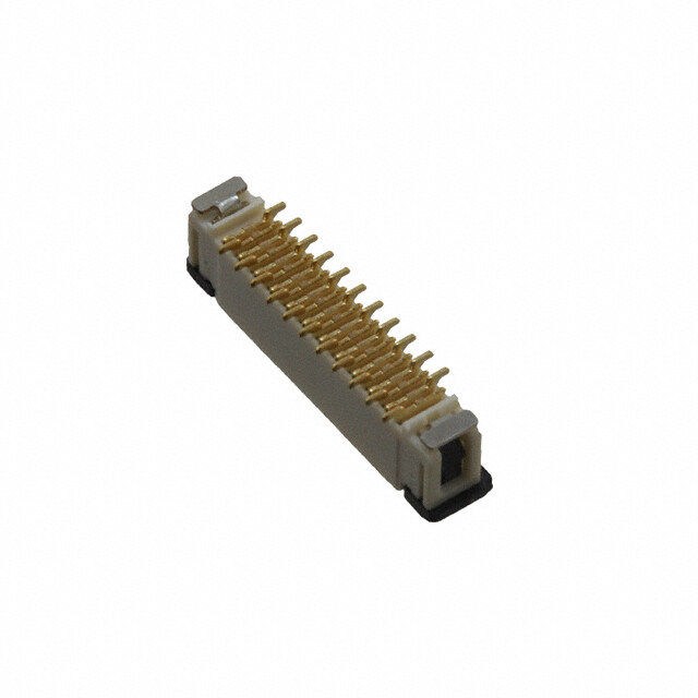
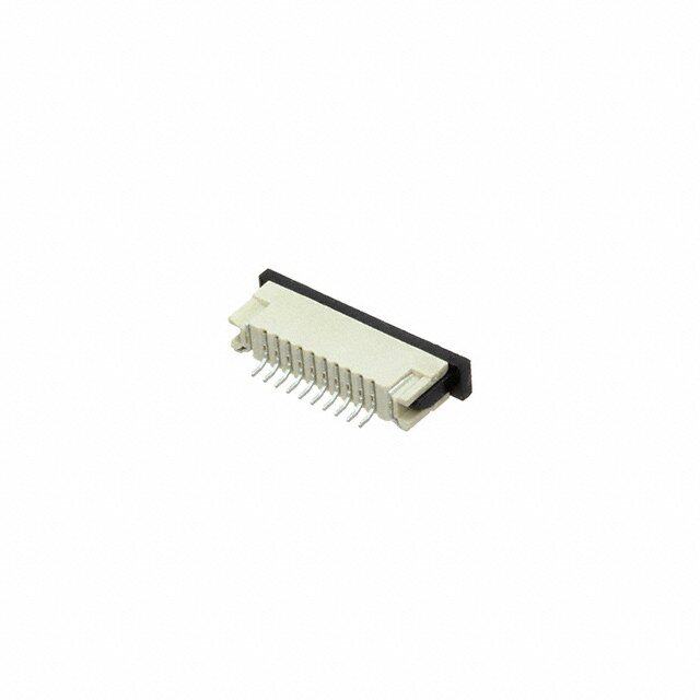
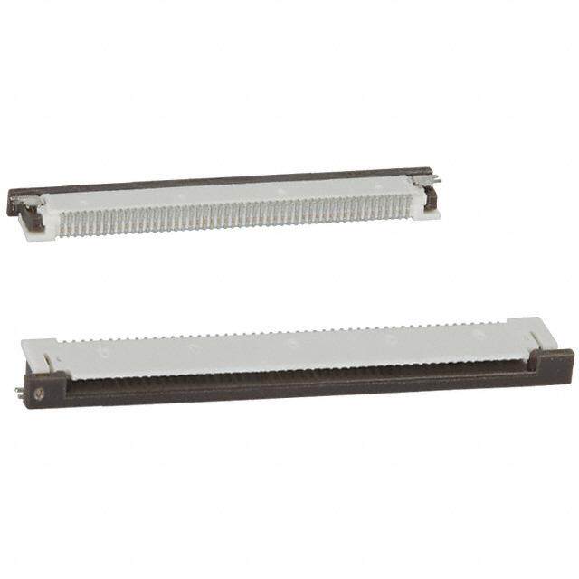
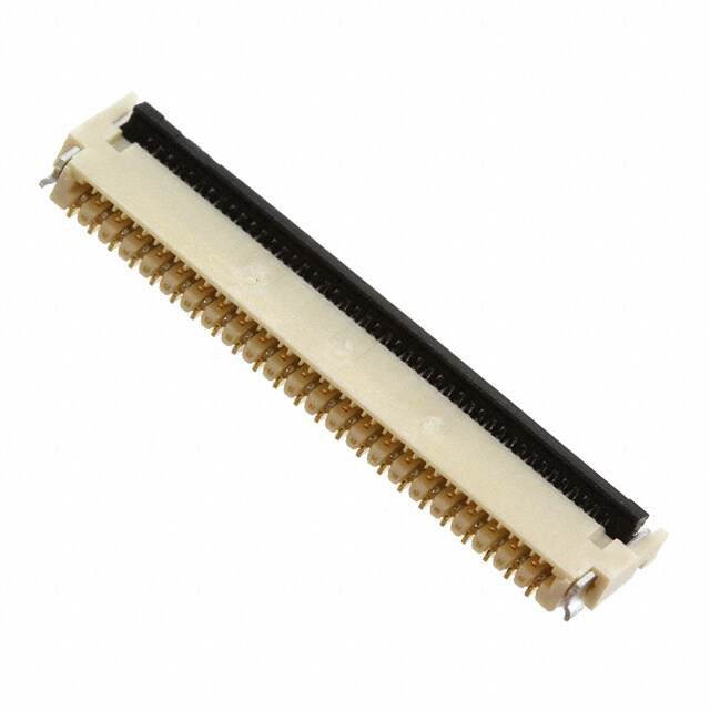
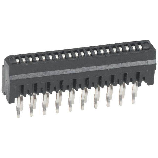
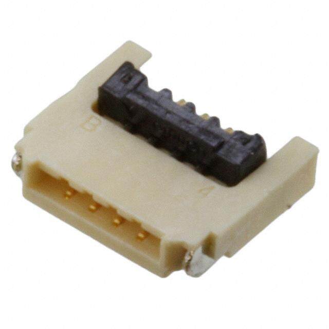
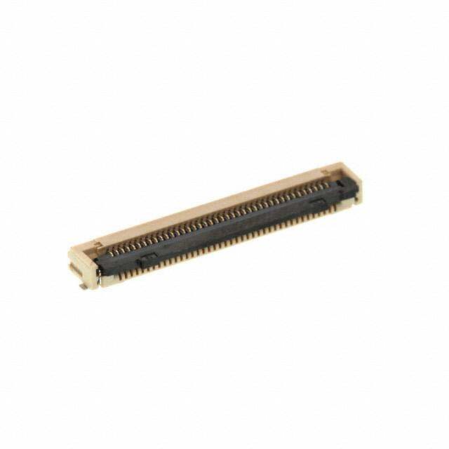
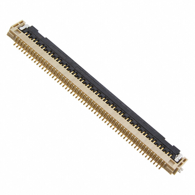
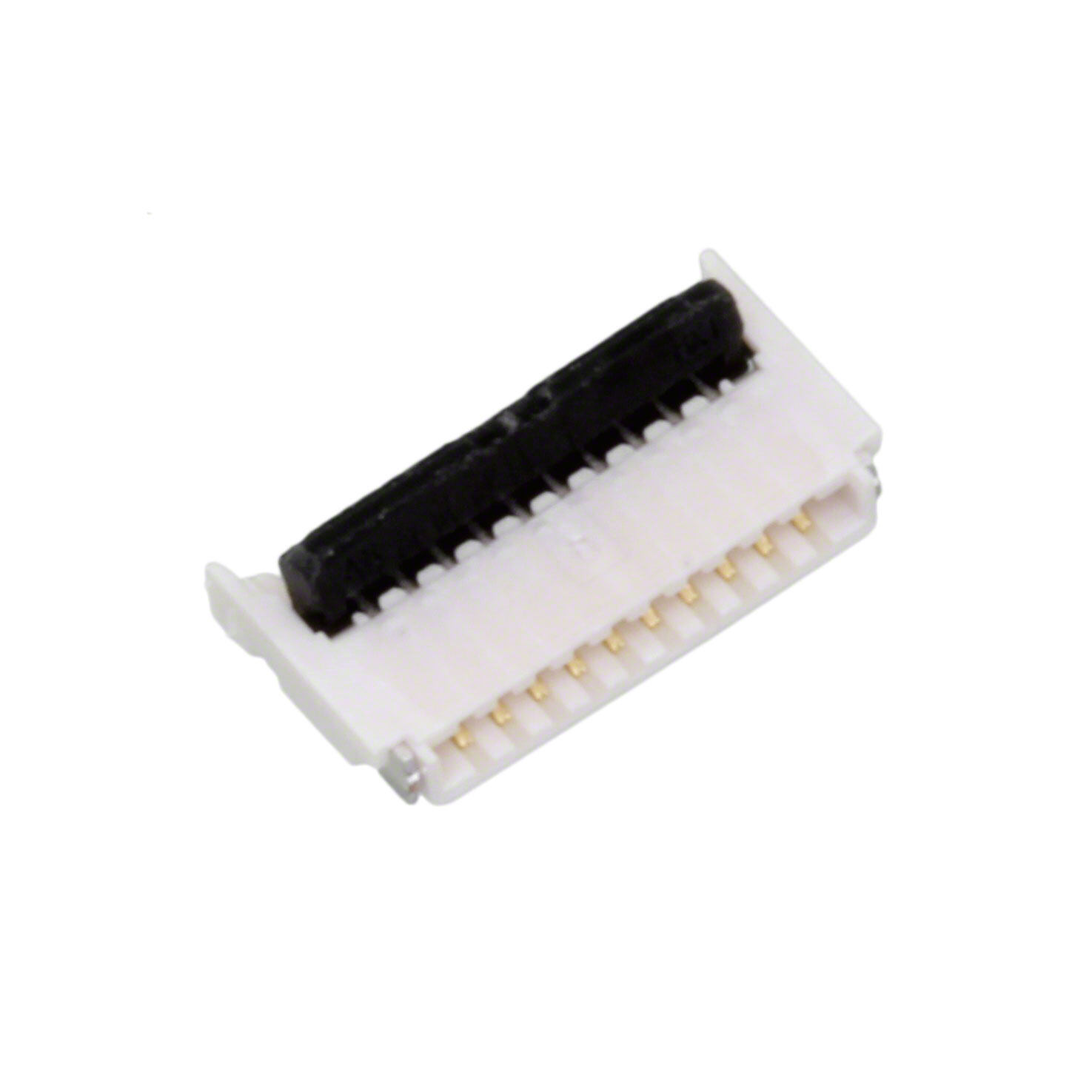
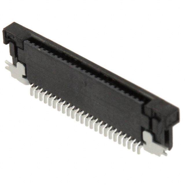
ICGOO电子元器件商城为您提供FH28E-40S-0.5SH(05)由Hirose Electric设计生产,在icgoo商城现货销售,并且可以通过原厂、代理商等渠道进行代购。 FH28E-40S-0.5SH(05)价格参考。Hirose ElectricFH28E-40S-0.5SH(05)封装/规格:FFC,FPC(扁平柔性)连接器, 40 位置 FFC,FPC 连接器 触点,底部 0.020"(0.50mm) 表面贴装,直角。您可以下载FH28E-40S-0.5SH(05)参考资料、Datasheet数据手册功能说明书,资料中有FH28E-40S-0.5SH(05) 详细功能的应用电路图电压和使用方法及教程。
Hirose Electric Co Ltd的FH28E-40S-0.5SH(05)是一款FFC(扁平柔性电缆)和FPC(柔性印刷电路)连接器,广泛应用于需要高密度、紧凑设计和可靠信号传输的电子设备中。这款连接器的主要应用场景包括:

1. 消费电子产品:
   - 智能手机和平板电脑:在这些设备中,空间非常有限,而FH28E-40S-0.5SH(05)连接器可以提供高效的空间利用率和可靠的电气性能,确保数据和信号的稳定传输。
   - 可穿戴设备:如智能手表、健康监测设备等,这类设备对体积和重量有严格要求,该连接器能够满足其紧凑设计的需求。

2. 汽车电子:
   - 车载信息系统:用于连接显示屏、摄像头和其他传感器,确保信号传输的稳定性和可靠性。
   - 自动驾驶系统:在自动驾驶车辆中,各种传感器和控制器之间的通信至关重要,该连接器可以提供稳定的信号传输,确保系统的正常运行。

3. 工业自动化:
   - 机器人和自动化设备:在工业环境中,设备的稳定性和可靠性非常重要,FH28E-40S-0.5SH(05)连接器能够承受恶劣的工作环境,提供稳定的信号传输。
   - 传感器和执行器:用于连接各种传感器和执行器,确保数据的准确传输和控制指令的及时响应。

4. 医疗设备:
   - 便携式医疗设备:如血糖仪、心电图机等,这类设备需要小巧轻便且性能可靠,该连接器可以满足其需求。
   - 诊断和治疗设备:如超声波设备、X光机等,连接器的高可靠性和稳定性对于确保设备的正常工作至关重要。

5. 通信设备:
   - 基站和路由器:在通信基础设施中,连接器的性能直接影响到信号的质量和传输效率,FH28E-40S-0.5SH(05)连接器可以提供稳定的信号传输,确保通信的顺畅。

总之,FH28E-40S-0.5SH(05)连接器凭借其紧凑的设计、高密度的引脚布局和可靠的电气性能,在多个领域中发挥着重要作用,尤其适用于对空间和性能有较高要求的应用场景。
| 参数 | 数值 |
| 产品目录 | |
| 描述 | CONN FPC 40POS 0.5MM SMD GOLDFFC & FPC连接器 40POS 0.5MM SMT GOLD |
| 产品分类 | |
| FFC,FCB厚度 | 0.30mm |
| 品牌 | Hirose Connector |
| 产品手册 | |
| 产品图片 |
|
| rohs | 符合RoHS无铅 / 符合限制有害物质指令(RoHS)规范要求 |
| 产品系列 | FFC & FPC连接器,Hirose Connector FH28E-40S-0.5SH(05)FH28 |
| 数据手册 | |
| 产品型号 | FH28E-40S-0.5SH(05) |
| 产品培训模块 | http://www.digikey.cn/PTM/IndividualPTM.page?site=cn&lang=zhs&ptm=21214 |
| 产品目录绘图 |
|
| 产品目录页面 | |
| 产品种类 | FFC & FPC连接器 |
| 产品类型 | Board Mount |
| 位置数量 | 40 |
| 其它名称 | *FH28E-40S-0.5SH(05) |
| 包装 | 剪切带 (CT) |
| 商标 | Hirose Connector |
| 外壳材料 | Liquid Crystal Polymer (LCP) |
| 安装类型 | 表面贴装,直角 |
| 安装角 | Right |
| 封装 | Reel |
| 工作温度 | - |
| 工厂包装数量 | 2000 |
| 扁平柔性类型 | FFC, FPC |
| 材料可燃性等级 | UL94 V-0 |
| 板上高度 | 0.100"(2.54mm) |
| 标准包装 | 1 |
| 特性 | 固定焊尾,零插入力(ZIF) |
| 特色产品 | http://www.digikey.com/cn/zh/ph/Hirose/FH28.html |
| 电压额定值 | 50 V |
| 电流额定值 | 500 mA |
| 电缆端类型 | 焊片式 |
| 端接 | |
| 端接类型 | SMD |
| 系列 | FH28 |
| 致动器材料 | 液晶聚合物(LCP), 不含卤素的 |
| 节距 | 0.5 mm |
| 触头材料 | 磷青铜 |
| 触头镀层 | 金 |
| 触点材料 | Phosphor Bronze |
| 触点电镀 | Gold |
| 连接器/触头类型 | 触点, 底部 |
| 针脚数 | 40 |
| 锁定功能 | 旋转锁 |
| 间距 | 0.020"(0.50mm) |
| 额定电压 | - |
| 额定电流 | - |

.JPG)


.jpg)
.jpg)
.jpg)


- 商务部:美国ITC正式对集成电路等产品启动337调查
- 曝三星4nm工艺存在良率问题 高通将骁龙8 Gen1或转产台积电
- 太阳诱电将投资9.5亿元在常州建新厂生产MLCC 预计2023年完工
- 英特尔发布欧洲新工厂建设计划 深化IDM 2.0 战略
- 台积电先进制程称霸业界 有大客户加持明年业绩稳了
- 达到5530亿美元!SIA预计今年全球半导体销售额将创下新高
- 英特尔拟将自动驾驶子公司Mobileye上市 估值或超500亿美元
- 三星加码芯片和SET,合并消费电子和移动部门,撤换高东真等 CEO
- 三星电子宣布重大人事变动 还合并消费电子和移动部门
- 海关总署:前11个月进口集成电路产品价值2.52万亿元 增长14.8%

.jpg)
PDF Datasheet 数据手册内容提取
0.5mm and 1mm Pitch, 2.55mm Height FPC/FFC Connectors FH28 Series Robust locking structure Reinforced fitting provide support and prevent the actuator from disengaging from the connector. Each terminal is attached to the actuator, so the actuator is supported along its entire length. d. e v r e s e R s ht g Ri All D. Fig.1 T L O., ■Features The FPC positioning mechanism and FPC tabs help to C 1. Highly reliable connection and robust structure guide and hold the FPC prior to engaging the actuator C RI Multi-polarized connectors, reinforced body structure and T high FPC retention produced by the following features: C Reliable connection created by its unique FPC/FFC E L positioning mechanism E E Prevents accidental disengagement with the design of its S proprietary structure O R 2. Simplified operations HI The flip lock structure makes it easier to engage/disengage 8 the actuator and reduces the required force needed to 1 0 operate. A clear tactile click is delivered upon the 2 ht successful completion of the mating process. (Fig.1) g 3. Increased FPC/FFC retention force ri y Vertical retention force for the FPC/FFC is 2.5 times p o stronger than our 0.5mm pitch connector the FH12 series. C 18 Hstorornizgoenr ttahla rne oteunr t0io.5nm fmor cpeit cfho rc othnnee FctPoCr t/hFeF CFH i1s2 2 s etirmieess Fig.2 20 *To realize the horizontal retention force values, the use 1. of the FPC positioning tabs are required. FPC without c. the positioning tabs will comply with the specifications Can also be used with straight sided, non-tabbed e D rated on the FH12 series. FPC/FFC 4. Accepts standard 0.3mm thick FPC/FFC It accepts 0.3mm thick products that are easy to manufacture and have superb insertion performance. 5. Fully molded structure aids PCB layout The bottom of this connector is enclosed by a fully molded structure that protects the contacts and removes any restrictions from PCB patterning and design. 6. Supports automatic pick-n-place mounting Offered in tape and reel packaging that is compatible with automatic machine mounting. (2,000pcs/reel) 7. Halogen-free All materials and substances used to produce this product comply with Halogen-free standards.*Defined according to IEC61249-2-21. Br : 900ppm maximum, Cl : 900ppm maximum, Br+Cl : 1,500ppm maximum Fig.3 8. Multiple packing options The standard packaging is 2,000pcs/reel, but it is also offered in a 500pcs/reel. (The outer diameter of the reel will be Ø330mm in this case.) 1 2016.3③
FFHH2288 SSeerriieess●●00..55mmmm aanndd 11mmmm PPiittcchh,, 22..5555mmmm HHeeiigghhtt FFPPCC//FFFFCC CCoonnnneeccttoorrss ■Product Specifications Operating Temperature Range Storage Temperature Range Rated Current 0.5A (Note 1) -40to+105ç(Note 2) -10to+50ç(Note 3) Ratings Rated Voltage AC 50Vrms Operating Humidity Range Storage Humidity Range Relative humidity 90% or less (no condensation shouldbe present) Relative humidity 90% or less (no condensation should be present) Adaptive FPC/FFC t= 0.3 ±0.05 Gold plating contact specifications Item Specification Conditions 1. Insulation Resistance Minimum of 500Mø Measured with DC 100V 2. Withstanding Voltage No flashover or breakdown AC 150Vrms is applied for 1 minute. Maximum of 50mø 3. Contact Resistance Measured at 1mA (DC or 1,000Hz) d. *including FPC/FFC conductor resistance e v Contact Resistance : Maximum of 50mø er 4. Durability 20 mating cycles s No damaged, cracked or looseness of parts e R s No electrical discontinuity of 1μsor greater Frequency: 10 to 55Hz ht 5. Vibration Resistance Contact Resistance : Maximum of 50mø Single amplitude of 0.75mm for 10 cycles in 3 axial g Ri No damages, cracks and looseness of parts directions All No electric discontinuity of 1μsor greater D. 6. Shock Resistance Contact Resistance : Maximum of 50mø Acceleration of 981m/s2, 6ms duaration, sine half-wave waveform 3 cycles in each of the 3 axis T No damaged, cracked or looseness of parts L O., Contact Resistance : Maximum of 50mø C 7. Humidity Resistance Insulation Resistance : Minimum of 50Mø 96 hours at temperature : 40çand humidity : 90 to 95% C of Steady State No damaged, cracked or looseness of parts RI T C Contact Resistance : Maximum of 50mø Temperature : -40/+15 to +35/+105/+15 to +35ç E 8. Temperature Cycles Insulation Resistance : Minimum of 50Mø Time : 30/2 to 3/30/2 to 3 minutes L E No damaged, cracked or looseness of parts 5 cycles E S 9. Solder Heat Should not have external deformity or loose Reflow : according to the Recommended Temperature Profile O R Resistance parts Hand solder: 350 ±5çfor 5 seconds HI 8 Note 1 : When energizing rated current to all contacts, use 70% of rated current. 1 Note 2 : Includes temperature rise caused by current flow. 0 2 Note 3 : The term "storage" here refers to products stored for a long period prior to board mounting and use. The operating temperature ht and humidity range covers the non-energized condition of connectors after board mounting and the temporary storage. g yri ■Materials / Finish p o C 8 Component Materials Color/Finish Remarks 1 LCP Gray 0 Insulator UL94V-0 2 LCP Black 1. c. Contact Phosphor bronze Gold plating --------------- De Metal fitting Brass Pure tin plating --------------- ■Product Number Structure Refer to the chart below when determining the product specifications from the product number. Please select from the product numbers listed in this catalog when placing orders. FH 28 D - 50 (25) S B - 0.5 SH (05) 1 2 3 4 5 6 7 8 9 10 1 Series Name : FH 6 Contact arrangement : Single (single row) 7 Eccentric direction : Blank…Standard type (without eccentricity) 2 Series No. : 28 B…Eccentric type (contacts on the opposite side of polarity mark) 3 None, D : Standard type E : Long reinforcing fitting type 8 Contact Pitch : 0.5mm, 1mm H : Space-saving type Standard type : The number of contacts 4 9 Mounting direction , SH...SMT horizontal mounting type Eccentric type : Number of contacts in 0.5mm housing 10 Specification : (05) …Gold plating, 2,000 pcs/reel Standard type : Blank (10) Specification:…Partial gold plating, 2,000 pcs/reel 5 Eccentric type : Actual number of pins (07)…Gold plating (for 40 contact only.), 2,000 pcs/reel (98)…Gold plating, 500 pcs/reel 2
FFHH2288 SSeerriieess●●00..55mmmm aanndd 11mmmm PPiittcchh,, 22..5555mmmm HHeeiigghhtt FFPPCC//FFFFCC CCoonnnneeccttoorrss ■Connector Dimensions [Standard type] 0.5mm pitch product A 0.5 (0.2) 9) 1. ( d. Contact mark B No. of contacts 6.5 ve 5.7 r e 1 2 1 2 s e 4) hts R 0.005MAX 2.55 (5. 0.05MA0X g (1.3) E Ri 0.1MAX 0.1MAX All C (FPC/FFC insertion dimensions) 1(2.2.85)4.5 0.7 D. D (3.65) T L O., C C RI T C Notes 1 The coplanarity of the metal fitting and contact is 0.1 MAX. E 2 The contact lead position shows the dimension from the E surface of the case bottom. L E 3 This product is sold in embossed, tape and reel packaging. For details on this product please refer to the “Packaging E S Specifications”located on page 9. O 4 Recesses in part structure may be added to improve molding characteristics. R HI Black marks may appear in the mold resin, but they will not negatively affect the performance of these connectors. 8 5 The color of the plating may change after the reflow process, but it will not negatively affect the performance of these connectors. 1 0 ght 2 ■Connector dimension table [Standard type] Unit : mm yri Part No. HRS No. No. of Contacts A B C D p Co FH28-10S-0.5SH(**) 586-1861-4 ** 10 4.5 9.9 5.57 9.58 8 FH28-15S-0.5SH(**) 586-1868-3 ** 15 7 12.4 8.07 12.08 1 0 FH28D-20S-0.5SH(**) 586-1823-5 ** 20 9.5 14.9 10.57 14.58 2 1. FH28D-28S-0.5SH(**) 586-1835-4 ** 28 13.5 18.9 14.57 18.58 c. De FH28D-30S-0.5SH(**) 586-1827-6 ** 30 14.5 19.9 15.57 19.58 FH28-40S-0.5SH(**) 586-1803-8 ** 40 19.5 24.9 20.57 24.58 FH28-45S-0.5SH(**) 586-1848-6 ** 45 22 27.4 23.07 27.08 FH28D-50S-0.5SH(**) 586-1808-1 ** 50 24.5 29.9 25.57 29.58 FH28D-55S-0.5SH(**) 586-1821-0 ** 55 27.0 32.4 28.07 32.08 FH28-60S-0.5SH(**) 586-1811-6 ** 60 29.5 34.9 30.57 34.58 FH28D-64S-0.5SH(**) 586-1813-1 ** 64 31.5 36.9 32.57 36.58 FH28D-68S-0.5SH(**) 586-1819-8 ** 68 33.5 38.9 34.57 38.58 FH28D-74S-0.5SH(**) 586-1828-9 ** 74 36.5 41.9 37.57 41.58 Note 1 : This product is sold in embossed, tape and reel packaging. This product is sold in full reel quantities of either 2,000 or 500 pcs/ reels. Please place orders by full reel quantities. 3
FH28 Series●0.5mm and 1mm Pitch, 2.55mm Height FPC/FFC Connectors ■Connector Dimensions [Standard type] 1mm pitch product (2.7) A (3.2) 1 (0.2) 9) 1. ( d. Contact mark B No. of contacts e v 6.5 er 5.7 s e 1 2 1 2 R hts 0.05MAX 55 (5.4) 0.05MAX Rig 0 2. 0 All 0.1MAX C (FPC/FFC inseDrtion dimensions) 1.2 (41..35) E 0.7 0.1MAX D. (2.85) T (3.65) L O., C C RI T C Notes 1 The lead flatness of metal fitting and contact is 0.1 MAX. E 2 The contact lead position shows the dimension from the E surface of the case bottom. L E 3 This product is sold in embossed, tape and reel packaging. For details on this product please refer to the “Packaging E S Specifications” located on page 9. O 4 Recesses in part structure may be added to improve molding characteristics R HI Black marks may appear in the mold resin, but they will not negatively affect the performance of these connectors. 8 5 The color of the plating may change after the reflow process, but it will not negatively affect the performance of these connectors. 1 0 ght 2 ■Connector dimension table [Standard type] Unit : mm yri Part No. HRS No. No. of Contacts A B C D p Co FH28D-20(10)SB-1SH(**) 586-1863-0 ** 10 9 14.9 10.57 14.58 8 FH28D-30(15)SB-1SH(**) 586-1860-1 ** 15 14 19.9 15.57 19.58 1 0 FH28-40(20)SB-1SH(**) 586-1832-6 ** 20 19 24.9 20.57 24.58 2 1. FH28D-50(25)SB-1SH(**) 586-1817-2 ** 25 24 29.9 25.57 29.58 c. De FH28-60(30)SB-1SH(**) 586-1818-5 ** 30 29 34.9 30.57 34.58 FH28D-64(32)SB-1SH(**) 586-1852-3 ** 32 31 36.9 32.57 36.58 FH28D-68(34)SB-1SH(**) 586-1812-9 ** 34 33 38.9 34.57 38.58 Note 1 : This product is sold in embossed, tape and reel packaging. This product is sold in full reel quantities of either 2,000 or 500 pcs/ reels. Please place orders by full reel quantities. 4
FH28 Series●0.5mm and 1mm Pitch, 2.55mm Height FPC/FFC Connectors ■Connector Dimensions [Space-saving type] A 0.5 (0.2) 9) 1. ( Contact mark No. of contacts d. B 6 e v 5.7 r se 1 2 1 2 e R Rights 00MAX 2.55 (5) 0MAX 0 (1.3) E All 0.15MAX 1.2 4.5 0.7 0.15MAX D. C (FPC/FFC insertion dimensions) (2.85) T D L (3.15) O., C C RI T C Notes 1 The lead flatness of metal fitting and contact is 0.1 MAX. E 2 The contact lead position shows the dimension from the E surface of the case bottom. L E 3 This product is sold in embossed, tape and reel packaging. For details on this product please refer to the “Packaging E S Specifications” located on page 9. O 4 Recesses in part structure may be added to improve molding characteristics R HI Black marks may appear in the mold resin, but they will not negatively affect the performance of these connectors. 8 5 The color of the plating may change after the reflow process, but it will not negatively affect the performance of these connectors. 1 0 ght 2 ■Connector dimension table [Space-saving type] Unit : mm yri Part No. HRS No. No. of Contacts A B C D p o FH28H-80S-0.5SH(**) 586-1805-3 ** 80 39.5 44.9 40.57 45.7 C 8 Note 1 : This product is sold in embossed, tape and reel packaging. This product is sold in full reel quantities of either 2,000 or 1 0 500 pcs/ reels. Please place orders by full reel quantities. 2 1. c. e D 5
FH28 Series●0.5mm and 1mm Pitch, 2.55mm Height FPC/FFC Connectors BRecommended PCB layout and metal mask dimensions for 0.5mm pitch products Recommended metal mask thickness: t= 0.15 ±0.1 JH±±00..11 ±0.1 JH±±00..11 mask) 2.2 1.8 etal m 5 ( ±0.1 ±0.1 ±0.0 3.9 4.2 1 0.1 nd) ± a ed. 1.3 0.5±0.05 0.3±0.03 (land) 0.1 (l 0.5±0.05 0.3±0.03 (land) erv A±0.05 0.25±0.03 (metal mask) 1.3± A±0.05 0.25±0.03 (metal mask) s e R Standard type (FH28, FH28D) Space-saving type (FH28H) s ht g Ri BRecommended FPC/FFC dimensions for 0.5mm pitch products All D. T L R CO., R0.2MA0.2MAX ±0.1 W ECTRIC 3.5MIN R0.2MXAX 1.4 2.8±0.1 4.5MIN SE EL R0.2 0.5±0.05 0.3±0.03 C0.5MAX 0.3±0.105 O 0.5±0.1 A±0.05 0.5±0.1 R HI F±0.07 8 G±0.1 1 0 2 ht g Notes 1 The stiffener needs to be a minimum of 0.188 (7.5 mil) thick. ri y 2 The W dimension needs to be a minimum of 0.5mm. p o C 8 1 0 2 1. BRecommended PCB layout, metal mask and FPC dimensions for ec. 0.5mm pitch products D Unit : mm Part No. HRS No. No. of Contacts F G H J FH28-10S-0.5SH(**) 586-1861-4 ** 10 5.5 7.1 10.6 7 FH28-15S-0.5SH(**) 586-1868-3 ** 15 8 9.6 13.1 9.5 FH28D-20S-0.5SH(**) 586-1823-5 ** 20 10.5 12.1 15.6 12.0 FH28D-28S-0.5SH(**) 586-1835-4 ** 28 14.5 16.1 19.6 16.0 FH28D-30S-0.5SH(**) 586-1827-6 ** 30 15.5 17.1 20.6 17.0 FH28-40S-0.5SH(**) 586-1803-8 ** 40 20.5 22.1 25.6 22.0 FH28-45S-0.5SH(**) 586-1848-6 ** 45 23 24.6 28.1 24.5 FH28D-50S-0.5SH(**) 586-1808-1 ** 50 25.5 27.1 30.6 27.0 FH28D-55S-0.5SH(**) 586-1821-0 ** 55 28.0 29.6 33.1 29.5 FH28-60S-0.5SH(**) 586-1811-6 ** 60 30.5 32.1 35.6 32.0 FH28D-64S-0.5SH(**) 586-1813-1 ** 64 32.5 34.1 37.6 34.0 FH28D-68S-0.5SH(**) 586-1819-8 ** 68 34.5 36.1 39.6 36.0 FH28D-74S-0.5SH(**) 586-1828-9 ** 74 37.5 39.1 42.6 39.0 FH28H-80S-0.5SH(**) 586-1805-3 ** 80 40.5 42.1 46.7 42.0 6
FH28 Series●0.5mm and 1mm Pitch, 2.55mm Height FPC/FFC Connectors BRecommended PCB layout and metal mask dimensions for 1mm pitch products Recommended metal mask thickness: t= 0.15 1 H±0.1 ±0. J±0.1 2 2. 1 0. ± 9 3. d. 1 serve 1.3±0. 1±0.05 00..32±5±0.00.30 3( la(mnde)tal mask) e R 1.75±0.1 A±0.05 1.25±0.1 s ht g Ri BRecommended FPC/FFC dimensions for 1mm pitch products All D. T L R CO., R0.2MA0.2MAX ±0.1 W C X 1.4 N ECTRI 3.5MIN R0.2MAX 2.8±0.1 4.5MI SE EL R0.2 0.5±0.05 0.3±0.03 C0.5MAX 0.3±0.105 O 0.5±0.1 A±0.05 0.5±0.1 R HI F±0.07 8 G±0.1 1 0 2 ht g Note 1 : The stiffener needs to be a minimum of 0.188 (7.5 mil) thick. yri Note 2 : The W dimension needs to be a minimum of 0.5mm. p o C 8 1 0 2 1. BRecommended PCB layout, metal mask and FPC dimensions for ec. 1mm pitch products D Unit : mm Part No. HRS No. No. of Contacts F G H J FH28D-20(10)SB-1SH(**) 586-1863-0 ** 10 10.5 12.1 15.6 12 FH28D-30(15)SB-1SH(**) 586-1860-1 ** 15 15.5 17.1 20.6 17 FH28-40(20)SB-1SH(**) 586-1832-6 ** 20 20.5 22.1 25.6 22 FH28D-50(25)SB-1SH(**) 586-1817-2 ** 25 25.5 27.1 30.6 27 FH28-60(30)SB-1SH(**) 586-1818-5 ** 30 30.5 32.1 35.6 32 FH28D-64(32)SB-1SH(**) 586-1852-3 ** 32 32.5 34.1 37.6 34 FH28D-68(34)SB-1SH(**) 586-1812-9 ** 34 34.5 36.1 39.6 36 7
FH28 Series●0.5mm and 1mm Pitch, 2.55mm Height FPC/FFC Connectors BFH28 Series FPC/FFC Material Configuration (Recommended Specifications) 1. Single-Sided FPC FPC : Flexible Printed Circuit Layer Materials Thickness (μm) Cover lay film Polymide 1mil (25) Cover adhesive (25) Under nickel plating 1~5μm+ Surface treatment 3 gold plating 0.2μm Copper foil Cu 1oz 35 Base adhesive Heat stiffener adhesive 25 d. Base film Polymide 1mil 25 ve Stiffener adhesive Heat stiffener adhesive 30 r se Reinforcing film Polymide 7mil 175 e R Total 293 s ht g Ri 2. Double-sided FPC FPC : Flexible Printed Circuit All D. Layer Materials Thickness (μm) T Cover lay film Polymide 1mil (25) L O., Cover adhesive (25) C Under nickel plating 1~5μm+ C Surface treatment gold plating 0.2μm 3 RI T Through hole copper Cu 15 C E Copper foil Cu 1/2oz 18 L E Base adhesive Heat stiffener adhesive 18 E S Base film Polymide 1mil 25 O R Base adhesive Heat stiffener adhesive 18 HI 8 Copper foil Cu 1/2oz (18) 1 0 Cover adhesive Heat stiffener adhesive 25 2 ht Cover lay film Polymide 1mil 25 g ri Stiffener adhesive Heat stiffener adhesive 50 y p Reinforcing film Polymide 4mil 100 o C 8 * Remove the copper foil on the back of double-sided FPC to avoid Total 297 1 damage due to FPC bending. 0 2 1. c. e 3. FFC FFC : Flexible Flat Cable D Layer Materials Thickness (μm) Polyester film 12 Adhesive Polyester thermal plasticity 30 Annealed copper foil (Gold plated 35 with under nickel plating) Adhesive Polyester type 30 Polyester 12 Adhesive Polyester type 30 Reinforcing film Polyester type 188 Total 295 Nominal thickness tolerance is approximately ±20μm. 1. These specifications are an example of the material configuration of an FPC/FFC (t= 0.3 ±0.05) used on the FH28 series. 2. Please contact the FPC/FFC manufacturer for the material configurations of their FPC/FFC. 8
FH28 Series●0.5mm and 1mm Pitch, 2.55mm Height FPC/FFC Connectors BPackaging Specifications [Common specifications for FH28 Series] ●Embossed Carrier Tape Dimensions (with a maximum tape width of 24mm) 1 0. (0(3.3)) 4±0.1 2±0.1512±0.1 Ø 1.5+ 0 .01 1.75± 1 0. ± Q)N)M0.3 (( ± K d. e (7.1) rv (8.5) e s e R s ht Standard type (FH28, FH28D) g Ri All ●Embossed Carrier Tape Dimensions (with a minimum tape width of 32mm) D. O., LT ((03.)3) 4±0.1 2±0.1512±0.1 Ø1.5+0.1 0 1.75±0.1 ((03.3)) 4±0.1 2±0.1512±0.1 Ø1.5+0.1 0 ±0.11.75 C C RI T EC M±0.1 M±0.1 L OSE E (Q) (N) L±0.1 K±0.3 (R)(Q)(N) ±0.1±0.3 LK R HI 8 1 0 2 ht Copyrig Unreeling Direction (7(8.1.5)) 1.5+ 00.1 +0.151.7 0 (6(.86)) 1.5+ 00.1+0.151.7 0 8 Unreeling Direction 1 0 2 Standard type (FH28, FH28D) Space-saving type (FH28H) 1. c. e D ●Reel Dimensions (Ø13) (S: Reel inner width) (Ø380) (Ø80) (T: Reel outer width) End section Loaded product section Leader section (minimum of 400 mm) Embossed Carrier Tape Empty pockets containing product Empty pockets Cover tape (minimum of 10 pockets) (minimum of 10 pockets) 9
FH28 Series●0.5mm and 1mm Pitch, 2.55mm Height FPC/FFC Connectors BPackaging specification dimensions [standard type] for 0.5mm pitch products Unit : mm Part No. HRS No. No. of Contacts K L M N Q S T FH28-10S-0.5SH(**) 586-1861-4 ** 10 ---------- 10.3 5.5 FH28-15S-0.5SH(**) 586-1868-3 ** 15 24 ---------- 11.5 12.8 8 25.4 29.4 FH28D-20S-0.5SH(**) 586-1823-5 ** 20 ---------- 15.3 10.5 FH28D-28S-0.5SH(**) 586-1835-4 ** 28 19.3 14.5 32 28.4 14.2 FH28D-30S-0.5SH(**) 586-1827-6 ** 30 20.3 15.5 33.4 37.4 FH28-40S-0.5SH(**) 586-1803-8 ** 40 25.3 20.5 FH28-45S-0.5SH(**) 586-1848-6 ** 45 27.8 23 44 40.4 20.2 FH28D-50S-0.5SH(**) 586-1808-1 ** 50 30.3 25.5 45.4 49.4 d. FH28D-55S-0.5SH(**) 586-1821-0 ** 55 32.8 28.0 e FH28-60S-0.5SH(**) 586-1811-6 ** 60 35.3 30.5 v er FH28D-64S-0.5SH(**) 586-1813-1 ** 64 37.3 32.5 s 56 52.4 26.2 57.4 61.4 e FH28D-68S-0.5SH(**) 586-1819-8 ** 68 39.3 34.5 R s FH28D-74S-0.5SH(**) 586-1828-9 ** 74 43.3 42.3 ht g Ri All BPackaging specification dimensions [standard type] for 1mm pitch D. products T L O., Unit : mm C Part No. HRS No. No. of Contacts K L M N Q S T C FH28D-20(10)SB-1SH(**) 586-1863-0 ** 10 24 ---------- 11.5 15.3 10.5 25.4 29.4 RI FH28D-30(15)SB-1SH(**) 586-1860-1 ** 15 32 28.4 14.2 20.3 15.5 33.4 37.4 T C FH28-40(20)SB-1SH(**) 586-1832-6 ** 20 25.3 20.5 E FH28D-50(25)SB-1SH(**) 586-1817-2 ** 25 44 40.4 20.2 30.3 25.5 45.4 49.4 L E FH28-60(30)SB-1SH(**) 586-1818-5 ** 30 35.3 30.5 E S FH28D-64(32)SB-1SH(**) 586-1852-3 ** 32 56 52.4 26.2 37.3 32.5 57.4 61.4 O FH28D-68(34)SB-1SH(**) 586-1812-9 ** 34 39.3 34.5 R HI 8 1 0 BPackaging specification dimensions [Space-saving type] 2 ht g Unit : mm ri y Part No. HRS No. No. of Contacts K L M N Q R S T p o FH28H-80S-0.5SH(**) 586-1805-3 ** 80 56 52.4 26.2 46.3 45.3 40.5 57.4 61.4 C 8 1 BRecommended soldering profile 0 2 1. ec. MAX 250ç Applicable Conditions D Reflow type : Far red/hot air reflow 250 Reflow furnace atmosphere: Atmosphere 230ç Soldering : Cream type Sn/3.0Ag/0.5Cu 200 200ç e (M705-221CM5-32-10.5 made ur at by Senju Metal Industry Co.) er Temp 150 150ç Testing PCB : Glass epoxy 55∞150∞1.6mm (ç) Land/metal mask dimensions Our recommendation conditions 100 This solder profile is based on the conditions provided above. 50 Please check the mounting conditions before use, 25ç (60 sec.) 90 to 120 seconds (60 sec.) conditions such as solder paste types, manufacturer, Pre-heating time Soldering Time PCB size and any other soldering materials may alter 0 the performance of such materials. Start Time (sec) 10
FH28 Series●0.5mm and 1mm Pitch, 2.55mm Height FPC/FFC Connectors BOperation Methods of Connector and Precautions Operation Methods Precautions for use 1. FPC/FFC insertion method 1 The actuator on the FH28 series connector is designed to open to a maximum of 116 degrees, trying 1 Rotate the actuator upward to unlock it to open it farther than that will lead to damage. The actuator can be easily operated with the use of a thumb nail or index finger. 116˚ d. e v r e s e R 2 Insert the FPC/FFC into the insertion slot s as show below. Improper insertion can ht lead to damage and ultimately malfunction. g Ri All 2 Ifancsee rfta tchineg FdPoCw/nF. FFCH 2w8i tihs tah eb octtoonmta ccot nstaucr-t Positioning part D. type connector. T L Insert FPC/FFC from the diagonally left O., side of the connector. Insert the FPC/FFC C at a diagonal angle and lay it into position. C Insert it until the FPC/FFC is securely RI hooked on the positioning area. Check to T C see if it is retained by pulling lightly on it. E For detail, refer to the next page. 3 Do not pull on the FPC/FFC in an upward L E direction, doing this can damage the con- E S nector as it is not equipped to handle a O large amount of force in this direction. R HI 8 1 0 2 ht g ri y p o C 8 3 Rotate the actuator downward. 1 4 When dealing with a higher contact count (80 posi- 0 2 tions), be sure to use two fingers to close the actuator 1. on both sides. Using one finger might not close it ec. completely and leave an incomplete connection. D 2. Removing the FPC/FFC 1 Rotate the actuator upward, then angle the 5 When inserting FPC/FFC, do not rub it hard on the lower sur- FPC/FFC upward after the actuator has been face of the insertion slot of the connector. Otherwise, the con- released and remove the FPC/FFC straight out. tact hits hard on the FPC/FFC, and may cause the deformation of the contact or conductor separation etc. of the FPC/FFC. During the insertion of the FPC/FFC, make sure that 11
FH28 Series●0.5mm and 1mm Pitch, 2.55mm Height FPC/FFC Connectors BCautions when mating FFFC/FPC with positioning tabs Operation Methods Precautions for use 1. Position for insertion 2 PC/FFC must not over lap Insert the cable into the gap ( ) between the side walls Do not close the actuator until the FPC/FFC has been ( ) on both sides of the cable insertion port' and the 'guide placed into its correct position. If it is sitting on the guides walls ( ) on both sides of the inner part of the connector' and the actuator closes onto it, it can cause damage and putting the tab of the cable on the gap. alter its performance. Incorrectly placed onto the left guide d. e v r e s e R s Incorrectly placed onto ht g the right guide Ri All D. 2. Cautions during insertion/mating T L O., 1 Dshoo wnon)t , itnhsise rtty pthee o fF aPcCti/oFnF mCa ay t caanu ssek tehwe ecdo rannegr loef (thaes Normal insertion C cable to get hooked and deform its contacts. C RI T C Skwed insertion E L E E S Do not close the actuator with O R the cable sitting on either guide. HI 8 1 0 2 ght Ihnosoekr tt hteh ec acbaleb ltea bs toranitgoh tth ein gtou idthee. connector opening and ri Pull the cable towards yourself with a slight force after y p insertion, and close the actuator after confirming that the o C cable tab is completely secured. 8 If it cannot be pulled to out, the cable can be determined to 1 0 be inserted into the correct position. 2 1. c. e Recommended mating method In case you accidentally close the lock with the cable sitting D on the guides, do not move the cable around to make it seat. Open the actuator immediately and reposition the 1 Insert the cable cable as explained in “1. Position for insertion” noted straight from the above. diagonally left side. 2 Pull the cable lightly to yourself and check if the tab is secured. Pulling direction 3 Close the actuator. The characteristics and the specifications contained herein are for reference purpose. Please refer to the latest customer drawings prior to use. 12 The contents of this catalog are current as of date of 03/2016. Contents are subject to change without notice for the purpose of improvements. Powered by TCPDF (www.tcpdf.org)
Mouser Electronics Authorized Distributor Click to View Pricing, Inventory, Delivery & Lifecycle Information: H irose Electric: FH28-40S-0.5SH(05) FH28-40S-0.5SH(11) FH28-50S-0.5SH(11) FH28-50S-0.5SH(51) FH28-60(30)SB-1SH(11) FH28-60S-0.5SH(11) FH28-60S-0.5SH(51) FH28B-20S-0.5SH(05) FH28B-40S-0.5SH(05) FH28B-50S-0.5SH(05) FH28B-68S-0.5SH(05) FH28BH-80S-0.5SH(05) FH28D-50S-0.5SH(51) FH28E-20S-0.5SH(11) FH28E-40S- 0.5SH(05) FH28H-80S-0.5SH(11) FH28-10S-0.5SH(11) FH28-55S-0.5SH(11) FH28B-20S-0.5SH(98) FH28B-40S- 0.5SH(98) FH28B-50S-0.5SH(98) FH28B-60S-0.5SH(05) FH28B-60S-0.5SH(98) FH28B-68S-0.5SH(98) FH28BH- 80S-0.5SH(10) FH28BH-80S-0.5SH(98) FH28D-68(34)SB-1SH(80) FH28-60S-0.5SH(39) FH28-40(20)SB-1SH(11)