ICGOO在线商城 > 连接器,互连器件 > FFC,FPC(扁平柔性)连接器 > FH19SC-18S-0.5SH(05)
.jpg)
 Datasheet下载
- 型号: FH19SC-18S-0.5SH(05)
- 制造商: Hirose Electric
- 库位|库存: xxxx|xxxx
- 要求:
| 数量阶梯 | 香港交货 | 国内含税 |
| +xxxx | $xxxx | ¥xxxx |
查看当月历史价格
查看今年历史价格
FH19SC-18S-0.5SH(05)产品简介:
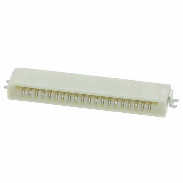
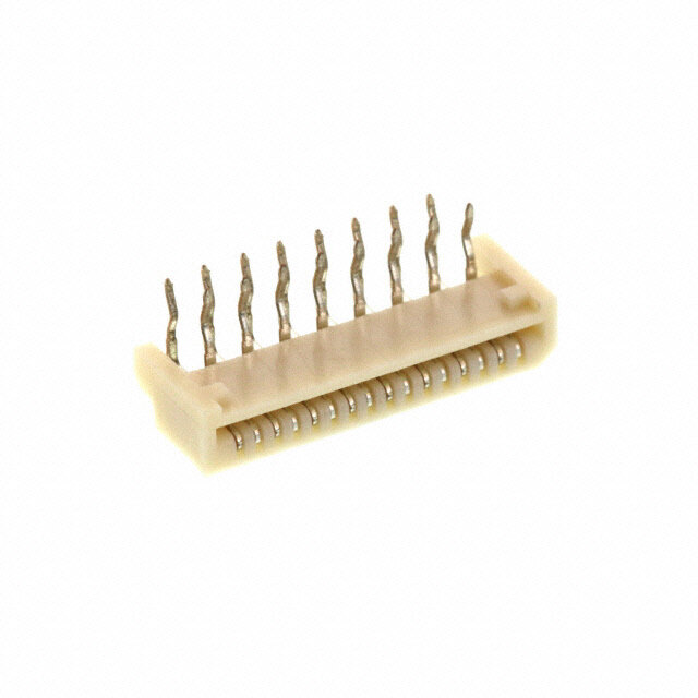
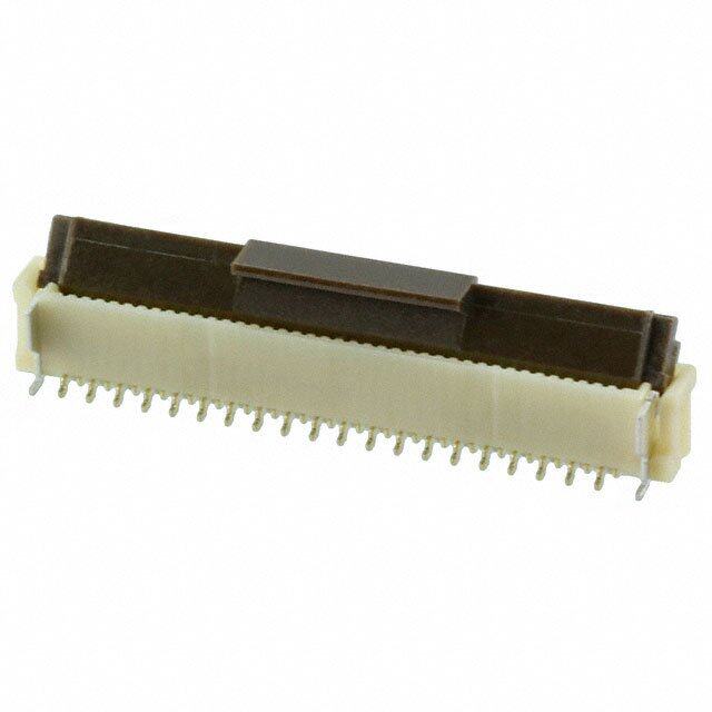
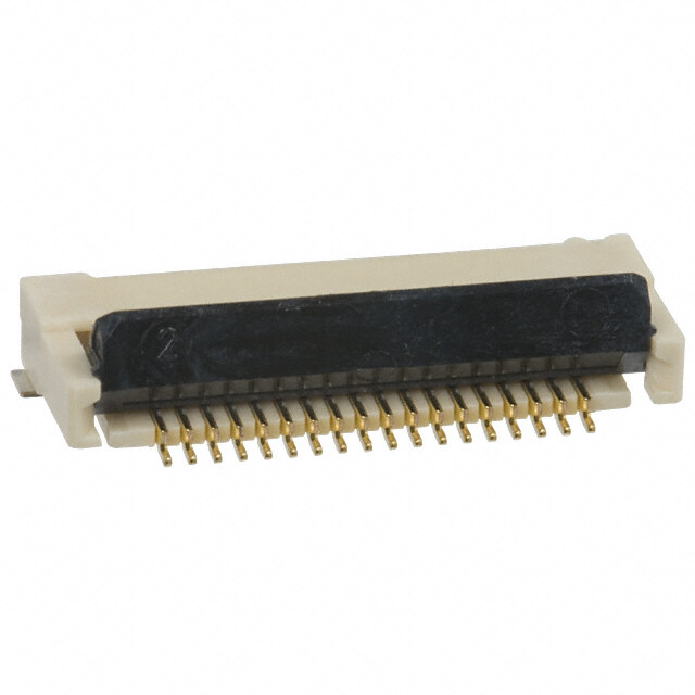
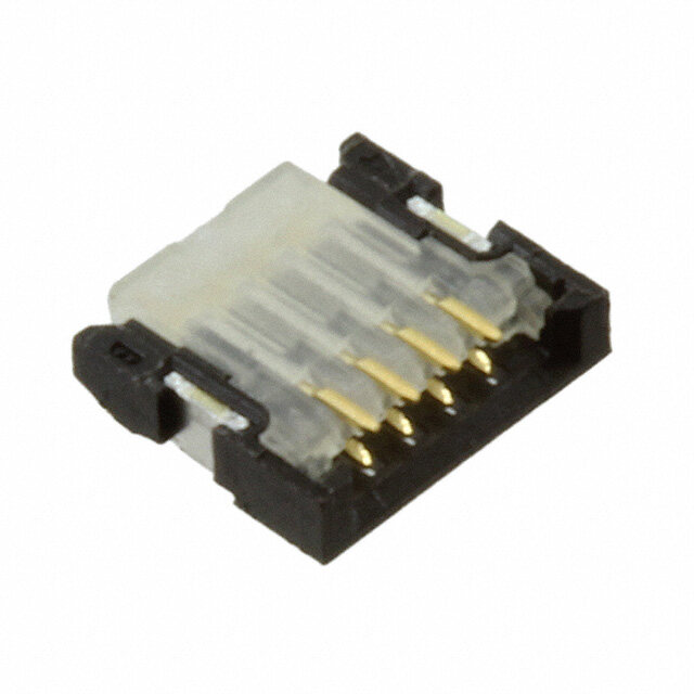
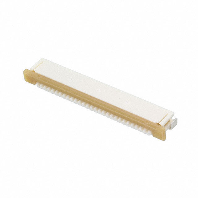
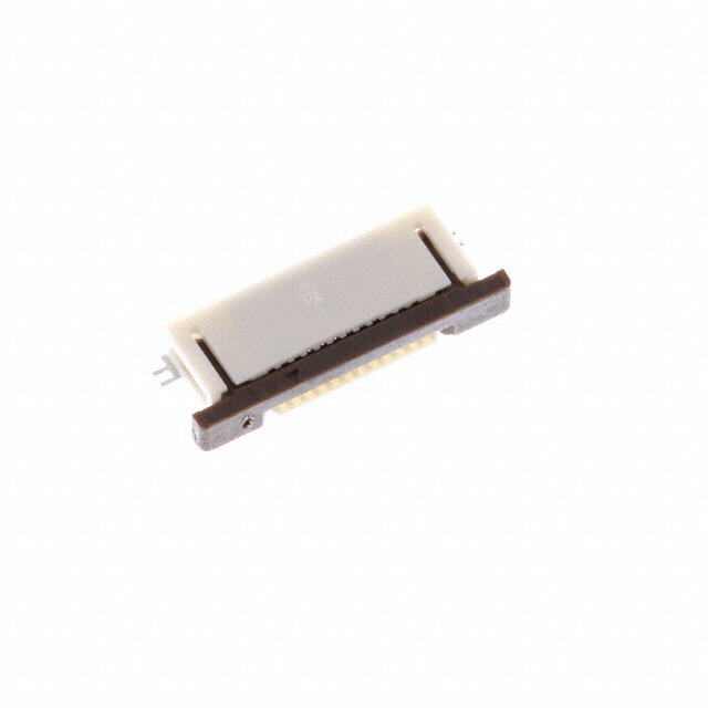
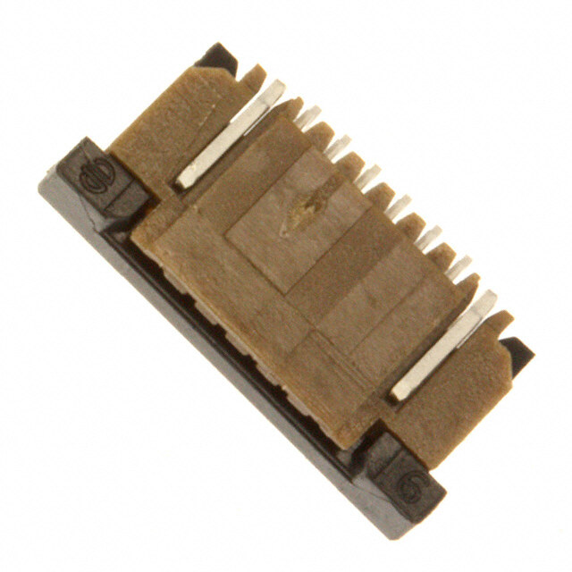
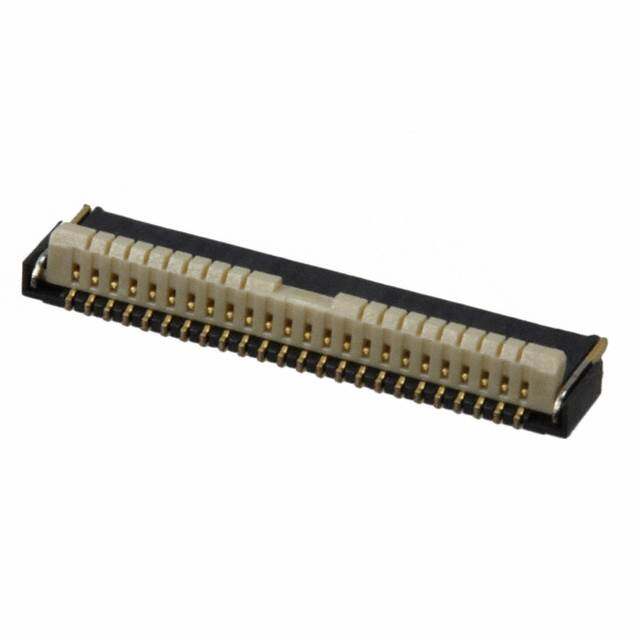
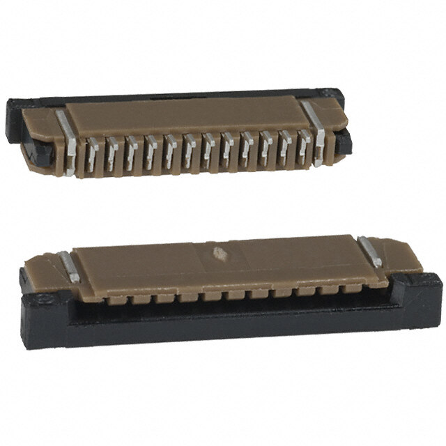
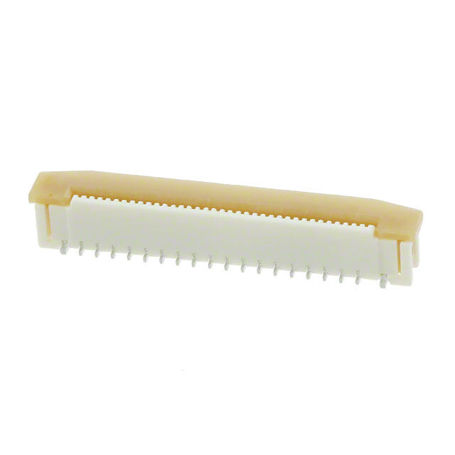
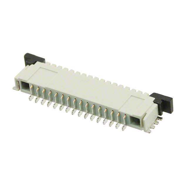
ICGOO电子元器件商城为您提供FH19SC-18S-0.5SH(05)由Hirose Electric设计生产,在icgoo商城现货销售,并且可以通过原厂、代理商等渠道进行代购。 FH19SC-18S-0.5SH(05)价格参考¥2.01-¥6.77。Hirose ElectricFH19SC-18S-0.5SH(05)封装/规格:FFC,FPC(扁平柔性)连接器, 18 位置 FFC,FPC 连接器 触点,底部 0.020"(0.50mm) 表面贴装,直角。您可以下载FH19SC-18S-0.5SH(05)参考资料、Datasheet数据手册功能说明书,资料中有FH19SC-18S-0.5SH(05) 详细功能的应用电路图电压和使用方法及教程。
FH19SC-18S-0.5SH(05) 是 Hirose Electric Co Ltd 生产的一款 FFC(扁平柔性电缆)和 FPC(柔性印刷电路)连接器。该型号的连接器广泛应用于消费电子、汽车电子、工业自动化以及医疗设备等领域,尤其适合需要高密度、轻量化和小型化设计的产品。

 应用场景:

1. 消费电子产品:
   - 例如智能手机、平板电脑、笔记本电脑等便携式设备中,FH19SC-18S-0.5SH(05) 连接器用于连接显示屏、摄像头模组和其他内部组件。其紧凑的设计和高可靠性确保了这些设备在有限空间内实现高效的数据传输和信号连接。

2. 汽车电子系统:
   - 在现代汽车中,这款连接器可以用于车载信息娱乐系统、仪表盘显示、高级驾驶辅助系统(ADAS)等。它能够承受车辆行驶过程中的振动和温度变化,提供稳定的电气连接。

3. 工业自动化:
   - 工业机器人、传感器模块、控制系统等设备中也常见该型号连接器的身影。它的高耐久性和抗干扰能力使其成为工业环境中可靠的选择,适用于各种复杂的布线需求。

4. 医疗设备:
   - 医疗成像设备、可穿戴健康监测装置等对连接器的要求极为严格,FH19SC-18S-0.5SH(05) 的低插入力设计和高精度接触点能够满足这些应用的需求,确保数据传输的准确性和稳定性。

5. 智能家居产品:
   - 智能音箱、智能门锁、安防摄像头等智能家居设备中,这款连接器用于内部模块间的连接,帮助实现更小体积和更高集成度的设计。

总之,FH19SC-18S-0.5SH(05) 连接器凭借其出色的性能和广泛的适用性,在多个领域发挥着重要作用,为各类电子设备提供了可靠的互连解决方案。
| 参数 | 数值 |
| 产品目录 | |
| 描述 | CONN FPC/FFC 18POS .5MM SMD GOLDFFC & FPC连接器 0.5MM 18 POS R/A SMT FFC/FPC THICK .3MM |
| 产品分类 | |
| FFC,FCB厚度 | 0.30mm |
| 品牌 | Hirose Connector |
| 产品手册 | |
| 产品图片 |
|
| rohs | 符合RoHS无铅 / 符合限制有害物质指令(RoHS)规范要求 |
| 产品系列 | FFC & FPC连接器,Hirose Connector FH19SC-18S-0.5SH(05)FH19SC |
| 数据手册 | |
| 产品型号 | FH19SC-18S-0.5SH(05) |
| 产品培训模块 | http://www.digikey.cn/PTM/IndividualPTM.page?site=cn&lang=zhs&ptm=19248 |
| 产品目录绘图 |
|
| 产品目录页面 | |
| 产品种类 | FFC & FPC连接器 |
| 产品类型 | Board Mount |
| 位置数量 | 18 |
| 其它名称 | FH19SC18S05SH05 |
| 包装 | 带卷 (TR) |
| 商标 | Hirose Connector |
| 外壳材料 | Liquid Crystal Polymer (LCP) |
| 安装类型 | 表面贴装,直角 |
| 安装角 | Right |
| 封装 | Reel |
| 工作温度 | -55°C ~ 85°C |
| 工厂包装数量 | 5000 |
| 扁平柔性类型 | FFC, FPC |
| 材料可燃性等级 | UL94 V-0 |
| 板上高度 | 0.037"(0.95mm) |
| 标准包装 | 5,000 |
| 特性 | 固定焊尾,零插入力(ZIF) |
| 特色产品 | http://www.digikey.cn/product-highlights/zh/fh19sc-series-connectors/51827 |
| 电压额定值 | 50 V |
| 电流额定值 | 500 mA |
| 电缆端类型 | 锥形 |
| 端接 | |
| 端接类型 | SMD |
| 系列 | FH19SC |
| 致动器材料 | 液晶聚合物(LCP), 聚苯硫醚(PPS) |
| 节距 | 0.5 mm |
| 触头材料 | 磷青铜 |
| 触头镀层 | 金 |
| 触点材料 | Phosphor Bronze |
| 触点电镀 | Gold |
| 连接器/触头类型 | 触点, 底部 |
| 针脚数 | 18 |
| 锁定功能 | 触发锁 |
| 间距 | 0.020"(0.50mm) |
| 额定电压 | 50V |
| 额定电流 | 0.5A |
| 驱动类型 | ZIF |

.jpg)
(SC).jpg)


.jpg)
(98).jpg)

- 商务部:美国ITC正式对集成电路等产品启动337调查
- 曝三星4nm工艺存在良率问题 高通将骁龙8 Gen1或转产台积电
- 太阳诱电将投资9.5亿元在常州建新厂生产MLCC 预计2023年完工
- 英特尔发布欧洲新工厂建设计划 深化IDM 2.0 战略
- 台积电先进制程称霸业界 有大客户加持明年业绩稳了
- 达到5530亿美元!SIA预计今年全球半导体销售额将创下新高
- 英特尔拟将自动驾驶子公司Mobileye上市 估值或超500亿美元
- 三星加码芯片和SET,合并消费电子和移动部门,撤换高东真等 CEO
- 三星电子宣布重大人事变动 还合并消费电子和移动部门
- 海关总署:前11个月进口集成电路产品价值2.52万亿元 增长14.8%

PDF Datasheet 数据手册内容提取
0.5 mm Pitch, 0.9 mm Height, FPC/FFC Connectors FH19C Series/FH19SC Series FH19C – FPC/FFC thickness: 0.2±0.03mm Actuator color: Brown d. e v FH19SC – FPC/FFC thickness: 0.3±0.03mm r e es Actuator color: Black R s ht g Ri All D. T L O., C C ■Features ● 0.9mm high (30 pos. shown) RI T C 1. Low-profile 0.5mm pitch FPC/FFC Connectors E L Miniaturization of portable equipment and personal E mobile devices has created increased demand for a low E 0.9mm S profile, high density, and high reliability connectors. HIRO *Tsmhea lldeer,s iwginth o af htheisig hcto onfn 0e.c9tomrm h aasn db eweidnt hm oafd 3em tmhin. ner and 17mm 3mm 8 *PCB footprint: Reduced approximately 48% (as compared 1 with Hirose Electric's 0.5mm pitch FH12 Series 0 ht 2 *cCoonnnneeccttoorrs )w eight: Reduced approximately 78% (as compared ● Can be mounted over conductive traces g ri with Hirose Electric's 0.5mm pitch FH12 Series connectors) y p o 2. Conductive traces on the PCB can run under C the connector 8 1 All bottom surface of the connector is solid, without any 0 2 exposure of the contact. 1. ep. 3. eParosvye ann Fdl irpe-lLiaobclek oApceturaattioorn System assures Enclosed construction S Rotating actuator permits easy insertion and reliable (No exposed contacts) Metal fittings connection with the FPC & FFC. (Leadless) Tactile sensation confirms complete mechanical locking of the actuator and the electrical connection. ● Metal Fittings (Leadless Type) 4. Accepts 0.2mm & 0.3mm thick FPC/FFC No protrusions on No exposed contacts on the bottom of the connector. the sides allows The connector will also terminate with 0.2mm thick Flat Flexible Cable (FFC). close side-by-side 5. Board placement with automatic equipment board placement. Flat upper surface and tape and reel packaging facilitate vacuum pick-up and placement. Standard reel packaging ● Actuator Temporary Hold Mechanism contains 5000 connectors. 6. Wide range of contact counts The contact positions available range from 4 to 50. 7. Satisfies Halogen-free requirements All materials and substances used in this product comply with the Halogen-free standards. * Defined according to IEC61249-2-21 Br: 900ppm max, Cl: 900ppm max, Br+Cl: 1,500ppm max Actuator stays open during insertion of the FPC/FFC. 2013.11w 1
FH19C & FH19SC Series●0.5mm pitch, 0.9mm above the board, Flexible Printed Circuit & Flexible Flat Cable ZIF Connectors ■Product Specifications Operating temperature range Storage temperature range Current rating 0.5 A (Note1) -55ç to +85ç(Note 2) -10ç to +50ç(Note 3) Rating Operating humidity range Storage humidity range Voltage rating 50 V AC Relative humidity 90% max. (No condensation) Relative humidity 90% max. (No condensation) Recommended FH19C Series Thickness: = 0.2 ±0.03mm Gold plated FPC, FFC FH19SC Series Thickness: = 0.3 ±0.03mm Gold plated Item Specification Conditions 1. Insulation resistance 500 M ohms min. 100 V DC 2. Withstanding voltage No flashover or insulation breakdown 150 V AC/1 minute 3. Contact resistance 100 m ohms max. 1 mA d. *Including FPC/FFC conductor resistance e v 4. Durability Contact resistance: 100 m ohms max. er (insertion/ withdrawal) No damage, cracks, or parts dislocation. 20 cycles s e R No electrical discontinuity of 1 μs or more. Frequency: 10 to 55 Hz, single amplitude of s 5. Vibration Contact resistance: 100 m ohms max. ht No damage, cracks, or parts dislocation. 0.75mm, 10 cycles in each of the 3 directions g Ri No electrical discontinuity of 1 μs. min. All 6. Shock Contact resistance: 100 m ohms max. Awcacveel ewraatvioenfo romf ,9 38 1c ymc/les2s, i6n measc dhu orfa tthioen ,3 sainxeis .half- D. No damage, cracks, or parts dislocation. T Contact resistance: 100 m ohms max. L 7. Humidity 96 hours at temperature of 40ç and humidity of O., (Steady state) INnos udlaatmioang ree,s cisratacnkcse, :o 1r 0p0a rMts odhismlosc amtiionn.. 90 to 95% C C Contact resistance: 100 m ohms max. Temperature: -55ç/ +15çto +35ç/ +85ç/+15çto +35ç RI 8. Temperature cycle Insulation resistance: 100 M ohms min. Time :-30 / 2 to 3 / +30 /2 to 3(Minutes) T No damage, cracks, or parts dislocation. 5 cycles C E 9. Resistance to Reflow: At the recommended temperature profile L soldering heat No deformation of components affecting performance. Manual soldering: 350ç±5çfor 5 seconds E E Note 1: When passing the current through all of the contacts, use 70% of the current rating. S O Note 2: Includes temperature rise caused by current flow. R Note 3: The term “storage” refers to products stored for long period of time prior to mounting and use. Operating Temperature HI Range and Humidity range covers non- conducting condition of installed connectors in storage, shipment or during 8 transportation.Information 1 0 ht 2 ■Materials g yri Part Material Finish Remarks p o Color: Beige C 8 Insulator LCP Color: Brown (FH19C Series) UL94V-0 1 Color: Black (FH19SC Series) 0 2 Contacts Phosphor bronze Gold plated ------- p.1. Metal fittings Phosphor bronze Pure tin reflow plated ------- e S ■Ordering information FH 19 C - 30S - 0.5 SH (05) 1 2 3 4 5 6 7 1 Series name : FH 5 Contact pitch : 0.5mm 2 Series No. : 19 6 Terminal type 3 C : FPCthickness : 0.2mm SH: SMT horizontal mounting type SC : FPC/FFC thickness : 0.3mm 7 Material and plating specifications : 4 No. of contacts : 4 to 50 FH19C : (10)...Gold plating with nickel barrier 5,000pieces/reel (99)...Gold plating with nickel barrier 500pieces/reel FH19SC : (09)...Gold plating with nickel barrier 5,000pieces/reel (99)...Gold plating with nickel barrier 500pieces/reel 2
FH19C & FH19SC Series●0.5mm pitch, 0.9mm above the board, Flexible Printed Circuit & Flexible Flat Cable ZIF Connectors ■Connector Dimension [FH19C Series] A±0.15 B 3 G s) d 0.5 ∞Number of c0o.n1t5acGts (0.15) +0.15 0 al lea 0.5 min er ct t d. A (1) 2.5±0.15 uding conta e cl eserv Polarizing mark indicator Number of contacts indicator (0.5) (130°) 9±0.1(In R 0. hts (1.6) g Ri (0.15) All (C: FPC insertion slot dimension) 2 1 0.15MAX 0.15MAX 1 2 TD. D±0.1 (1.3) S L O., 2.15±0.2 C C Notes 1 The coplanarity of each terminal lead and metal fitting is within 0.1mm. RI 2 The contact terminal lead position indicates the dimension from the bottom surface of the insulator body. T C 3 Difference between terminal contact to be max. 0.1mm. E L 4 Packaged on tape and reel only. Check packaging specification. E E 5 Any discoloration of the plastic compound will NOT AFFECT form, fit or function of the connector. S 6 After reflow, the terminal plating may change color, however this does not represent a quality issue. O R HI Unit: mm 8 Part Number CL No. Number of Contacts A B C D 1 0 2 FH19C-04S-0.5SH(**) 580-0410-1-** 4 4 1.5 2.57 3.35 ht FH19C-05S-0.5SH(**) 580-0418-3-** 5 4.5 2 3.07 3.85 g yri FH19C-06S-0.5SH(**) 580-0409-2-** 6 5 2.5 3.57 4.35 p Co FH19C-07S-0.5SH(**) 580-0411-4-** 7 5.5 3 4.07 4.85 8 FH19C-08S-0.5SH(**) 580-0404-9-** 8 6 3.5 4.57 5.35 1 0 FH19C-09S-0.5SH(**) 580-0403-6-** 9 6.5 4 5.07 5.85 2 1. FH19C-10S-0.5SH(**) 580-0412-7-** 10 7 4.5 5.57 6.35 p. e FH19C-12S-0.5SH(**) 580-0413-0-** 12 8 5.5 6.57 7.35 S FH19C-13S-0.5SH(**) 580-0405-1-** 13 8.5 6 7.07 7.85 FH19C-15S-0.5SH(**) 580-0406-4-** 15 9.5 7 8.07 8.85 FH19C-17S-0.5SH(**) 580-0408-0-** 17 10.5 8 9.07 9.85 FH19C-20S-0.5SH(**) 580-0402-3-** 20 12 9.5 10.57 11.35 FH19C-21S-0.5SH(**) 580-0414-2-** 21 12.5 10 11.07 11.85 FH19C-24S-0.5SH(**) 580-0407-7-** 24 14 11.5 12.57 13.35 FH19C-27S-0.5SH(**) 580-0401-0-** 27 15.5 13 14.07 14.85 FH19C-30S-0.5SH(**) 580-0400-8-** 30 17 14.5 15.57 16.35 FH19C-34S-0.5SH(**) 580-0419-6-** 34 19 16.5 17.57 18.35 FH19C-40S-0.5SH(**) 580-0416-8-** 40 22 19.5 20.57 21.35 FH19C-50S-0.5SH(**) 580-0417-0-** 50 27 24.5 25.57 26.35 Note1: Embossed tape reel packaging (5,000 pieces/reel, 500 pieces/reel). Order by number of reels. 3
FH19C & FH19SC Series●0.5mm pitch, 0.9mm above the board, Flexible Printed Circuit & Flexible Flat Cable ZIF Connectors [FH19SC Series] A±0.15 3 B G s) 0.5 ∞Number of contacts (0.15) +0.15 0 al lead 0.15 G 5 n 0. mi er ct t a (1) 0.15 cont ± g 5 n 2. di A u cl n d. 5 1(I erve Polarizing mark indicator Number of contacts indicator (0.5) (130°) 93±0. es 6) 0. R 1. s ( ht (0.15) g Ri (C: FPC insertion slot dimension) 2 1 0.15MAX 0.15MAX 1 2 All D±0.1 (1.3) S D. T 2.15±0.2 L O., Notes 1 The coplanarity of each terminal lead and metal fitting is within 0.1mm. C 2 The contact terminal lead position indicates the dimension from the bottom surface of the insulator body. C 3 Difference between terminal contact to be max. 0.1mm. RI 4 Any discoloration of the plastic compound will NOT AFFECT form, fit or function of the connector. T C 5 The contacts are protruding. 0.03mm max. from the housing top surface. E 6 Packaged on tape and reel only. Check packaging specification. L E E 7 After reflow, the terminal plating may change color, however this does not represent a quality issue. Unit: mm S Part Number CL No. Number of Contacts A B C D O R FH19SC-12S-0.5SH(**) 580-0512-1-** 12 8 5.5 6.57 7.35 HI FH19SC-13S-0.5SH(**) 580-0518-8-** 13 8.5 6 7.07 7.85 8 1 FH19SC-14S-0.5SH(**) 580-0509-7-** 14 9 6.5 7.57 8.35 0 2 FH19SC-15S-0.5SH(**) 580-0503-0-** 15 9.5 7 8.07 8.85 ht FH19SC-16S-0.5SH(**) 580-0521-2-** 16 10 7.5 8.57 9.35 g yri FH19SC-17S-0.5SH(**) 580-0504-3-** 17 10.5 8 9.07 9.85 p o FH19SC-18S-0.5SH(**) 580-0519-0-** 18 11 8.5 9.57 10.35 C 8 FH19SC-20S-0.5SH(**) 580-0502-8-** 20 12 9.5 10.57 11.35 1 FH19SC-21S-0.5SH(**) 580-0505-6-** 21 12.5 10 11.07 11.85 0 2 1. FH19SC-22S-0.5SH(**) 580-0506-9-** 22 13 10.5 11.57 12.35 p. FH19SC-24S-0.5SH(**) 580-0511-9-** 24 14 11.5 12.57 13.35 e S FH19SC-26S-0.5SH(**) 580-0510-6-** 26 15 12.5 13.57 14.35 FH19SC-27S-0.5SH(**) 580-0516-2-** 27 15.5 13 14.07 14.85 FH19SC-28S-0.5SH(**) 580-0513-4-** 28 16 13.5 14.57 15.35 FH19SC-30S-0.5SH(**) 580-0500-2-** 30 17 14.5 15.57 16.35 FH19SC-32S-0.5SH(**) 580-0514-7-** 32 18 15.5 16.57 17.35 Note1: Embossed tape reel packaging (5,000 pieces/reel, 500pieces/reel) . Order by number of reels. 4
FH19C & FH19SC Series●0.5mm pitch, 0.9mm above the board, Flexible Printed Circuit & Flexible Flat Cable ZIF Connectors ■ Recommended PCB Land and Metal Mask Dimensions [Common to FH19C & FH19SC Series] Recommended metal mask thickness: 0.10 mm. B 5 H 0 ∞Number of contacts ±0. 0.5 0.1H0.3±0.05(Land) 15) 0.8 0.25±0.05 (Metal mask) (0. 3.3±0.05 0.15)(0.15) (2.5) (3) d. ( e v r e (0.05) Res ±0.05 J±0.1 (0.2) (0.15) hts 0.8 K±0.1 g (A) Ri All D. T ■Recommended FPC, FFC Dimensions L O., [Common to FH19C & FH19SC Series] C C RI L±0.05 T ELEC 0.5±0.07 0.5±0.03 B±0.03 00..335±±00.0.033((FFFPCC)) 2-R0.2 FH109.2C± S0.e0r3ies FH109.S3±C0 .S0e3ries E S O s) right 2018 HIR 2.5±0.3(Exposed trace 3.5 min. (Stiffener) 3.5 min. (Stiffener) y p o C 8 ()X 1 0 2 Note 1: Stiffener dimension should be 3.5mm min., and X dimension should be 0.5mm for improved flexibility of FPC. 1. p. e S Unit: mm Unit: mm Number of Contacts A B J K L Number of Contacts A B J K L 4 4.0 1.5 3.1 3.9 2.5 20 12.0 9.5 11.1 11.9 10.5 5 4.5 2.0 3.6 4.4 3.0 21 12.5 10.0 11.6 12.4 11.0 6 5.0 2.5 4.1 4.9 3.5 22 13.0 10.5 12.1 12.9 11.5 7 5.5 3.0 4.6 5.4 4.0 24 14.0 11.5 13.1 13.9 12.5 8 6.0 3.5 5.1 5.9 4.5 26 15.0 12.5 14.1 14.9 13.5 9 6.5 4.0 5.6 6.4 5.0 27 15.5 13.0 14.6 15.4 14.0 10 7.0 4.5 6.1 6.9 5.5 28 16.0 13.5 15.1 15.9 14.5 12 8.0 5.5 7.1 7.9 6.5 30 17.0 14.5 16.1 16.9 15.5 13 8.5 6.0 7.6 8.4 7.0 32 18.0 15.5 17.1 17.9 16.5 14 9.0 6.5 8.1 8.9 7.5 34 19.0 16.5 18.1 18.9 17.5 15 9.5 7.0 8.6 9.4 8.0 40 22.0 19.5 21.1 21.9 20.5 16 10.0 7.5 9.1 9.9 8.5 45 24.5 22.0 23.6 24.4 23.0 17 10.5 8.0 9.6 10.4 9.0 50 27.0 24.5 26.1 26.9 25.5 18 11.0 8.5 10.1 10.9 9.5 5
FH19C & FH19SC Series●0.5mm pitch, 0.9mm above the board, Flexible Printed Circuit & Flexible Flat Cable ZIF Connectors ■FH19C & FH19SC Series FPC/FFC Construction (Recommended Specifications) 1. Using Single-sided FPC FPC : Flexible Printed Circuit Thickness (μm) Material Name Material FH19C FH19SC Covering layer film Polyimide 1 mil thick (25) (25) Cover adhesive (25) (25) Nickel under plated 1 to 5μm / Surface treatment 3 3 Gold plated 0.2μm Copper foil Cu 1oz 35 35 Base adhesive Thermosetting adhesive 25 25 d. Base film Polyimide 1 mil thick 25 25 e v Reinforcement material adhesive Thermosetting adhesive 30 30 r e Polyimide FH19C :3mil es Stiffener 75 175 R FH19SC:7mil s Total 193 293 ht g Ri All 2. Using Double-sided FPC FPC : Flexible Printed Circuit D. Thickness (μm) T Material Name Material FH19C FH19SC L O., Covering layer film Polyimide 1 mil thick (25) (25) C Cover adhesive (25) (25) C Nickel under plated 1 to 5μm / RI Surface treatment 3 3 Gold plated 0.2μm T C Through-hole copper Cu 15 15 E L E Copper foil Cu 1/2oz 18 18 E Base adhesive Thermosetting adhesive 18 18 S O Base film Polyimide 1 mil thick 25 25 R HI Base adhesive 18 18 8 1 Copper foil Cu 1/2oz 18 18 0 2 Cover adhesive Thermosetting adhesive 25 25 ht g Covering layer film Polyimide 1 mil thick 25 25 ri py Reinforcement material adhesive Thermosetting adhesive 25 50 o C Polyimide FH19C :1mil 8 Stiffener FH19SC:4mil 25 100 1 Total 197 297 0 2 p.1. 3. Using FFC (Flexible Flat Cable) FFC : Flexible Flat Cable e S Thickness (μm) Material Name Material FH19C FH19SC Polyester film (12) (12) Adhesive Polyester thermoplastic type (30) (30) (Nickel under plated / Gold plated), soft copper film 35 35 Adhesive Polyester 30 30 Polyester 12 12 Adhesive Polyester 30 30 Stiffener Polyester 100 188 Total 207 295 * Practical tolerance of thickness dimension is ±20μm (i.e., 187 to 227μm). 4. Precautions 1. This specification is a recommendation for the construction of the FH19C/FH19SC Series FPC and FFC (t=0.2/0.3±0.03). 2. For details about the construction, please contact the FPC/FFC manufacturers. 6
FH19C & FH19SC Series●0.5mm pitch, 0.9mm above the board, Flexible Printed Circuit & Flexible Flat Cable ZIF Connectors ■ Packaging Specifications [Common to FH19C & FH19SC Series] ●Embossed Carrier Tape Dimensions (1.7) 4±0.1 2±0.15 8±0.1 1 (0.3) Ø1.5+0. 10 1.75±0. 1 0. ± Q) N 3 ( 0. ± M d. e v r e s Re (3.3) Flat surface for placement s Unreeling direction (4.3) with automatic equipment ht g Ri (1) All D. T L O., ●Reel Dimensions 13) C (Ø (R:INSIDE) C RI T C E SE EL (Ø380) (Ø80) O R HI 8 (T:OUTSIDE) 1 0 2 ht g End cection Mounting cection Lead cection (400 mm min.) ri y p o C 8 1 0 2 1. p. e Blank cection Embossed carrier tape Blank cection Top cover tape S (10 pockets min.) (10 pockets min.) Unit: mm Unit: mm Number of Contacts M N Q R T Number of Contacts M N Q R T 4 16 7.5 4.3 17.4 21.4 20 24 11.5 12.3 25.4 29.4 5 16 7.5 4.8 17.4 21.4 21 24 11.5 12.8 25.4 29.4 6 16 7.5 5.3 17.4 21.4 22 24 11.5 13.3 25.4 29.4 7 16 7.5 5.8 17.4 21.4 24 24 11.5 14.3 25.4 29.4 8 16 7.5 6.3 17.4 21.4 26 24 11.5 15.3 25.4 29.4 9 16 7.5 6.8 17.4 21.4 27 24 11.5 15.8 25.4 29.4 10 16 7.5 7.3 17.4 21.4 28 24 11.5 16.3 25.4 29.4 12 16 7.5 8.3 17.4 21.4 30 24 11.5 17.3 25.4 29.4 13 16 7.5 8.8 17.4 21.4 32 32 14.2 18.3 33.4 37.4 14 16 7.5 9.3 17.4 21.4 34 32 14.2 19.3 33.4 37.4 15 16 7.5 9.8 17.4 21.4 40 44 20.2 22.3 45.4 49.4 16 24 11.5 10.3 25.4 29.4 45 44 20.2 24.8 45.4 49.4 17 24 11.5 10.8 25.4 29.4 50 44 20.2 27.3 45.4 49.4 18 24 11.5 11.3 25.4 29.4 Note: Embossed tape 32 mm or wider will have perforated feed holes on two sides. 7
FH19C & FH19SC Series●0.5mm pitch, 0.9mm above the board, Flexible Printed Circuit & Flexible Flat Cable ZIF Connectors ■ Recommended Temperature Profile [For FH19C & FH19SC Series] MAX 250ç HRS test condition Solder method :Reflow, IR/hot air 250 230ç Solder composition :Paste, 96.5%Sn/3.0%Ag/0.5%Cu 200 200ç (Senju Metal Industry, Co., ç) Ltd.’s Part d. ure( Number:M705-221CM5-32- erve mperat 150 150ç 10.5) es Te Test board :Glass epoxy R 45mm∞100mm∞1.6mm thick s 100 ht Land dimensions :0.3mm∞0.8mm g Ri Metal mask :0.25mm∞0.8mm∞0.1mm All 50 D. 25ç(60 sec.) 90 sec. to 120 sec. (60 sec.) This temperature profile is based on the above T conditions. L O., 0 Start Preheating Soldering In individual applications the actual temperature may C vary, depending on solder paste type, C Time (Seconds) volume/thickness and board size/thickness. Consult RI T tour solder paste and equipment manufacturer for C E specific recommendations. L E E S O R HI 8 1 0 2 ht g ri y p o C 8 1 0 2 1. p. e S 8
FH19C & FH19SC Series●0.5mm pitch, 0.9mm above the board, Flexible Printed Circuit & Flexible Flat Cable ZIF Connectors ■Connector Operation and Precautions Operation Precautions 1. FPC/FFC Termination procedure. 1) Do not apply excessive force or use any type Connector installed on the board. of tool to operate the actuator. 1) Lift up the actuator. Use thumb or index fin- ger. d. e v 2) The connector will assure reliable performance r e when the actuator is open to 130° maximum. s Re Do not exceed this angle, as this may cause s permanent damage to the connector. ht g Ri 2) Assure that the FPC/FFC is fully inserted All parallel to mounting surface, with the D. exposed conductive traces facing down. T L O., C C RI T C E FPC conductor surface 3) Insert the FPC/FFC straight into the insertion open- L (Bottom side) ing. Failing to follow this precaution can lead to E E damaging the FPC/FFC and altering its connectivity. HIROS 3) RImt ooistv acetredit idaconawdl t nhre atmht etah iaenc sitn ufsuaeltloyrt rei nudsn eFtirPlt efCird/mF. SlFyCh co lioussl dneodt. FPC·FFC insertion opening 8 the FPC/FFC be moved, open the actuator 1 0 and repeat the process, starting with Step 1 2 ht above. g ri y p o C 4) When you insert the FPC into the insertion open- 8 ing, do not apply excessive pressure or scrape 1 0 the FPC on the bottom of the opening. Doing so 2 1. can lead to deformities of the contacts and can p. hinder the performance of the connector. e S 2. FPC/FFC Removal 1) Lift up the actuator. 2) Carefully remove the FPC/FFC. 5) Application of excessive force to the inserted FPC/FFC may cause damage to connector and may affect the reliability of electrical con- nection. If specific applica- tion requires con- tinuous or repeated pull or bend of the inserted FPC/FFC, assure that the forces are NOT transmitted directly to the connector. 9
FH19C & FH19SC Series●0.5mm pitch, 0.9mm above the board, Flexible Printed Circuit & Flexible Flat Cable ZIF Connectors NOTES : d. e v r e s e R s ht g Ri All D. T L O., C C RI T C E L E E S O R HI 8 1 0 2 ht g ri y p o C 8 1 0 2 1. p. e S 10
FH19C & FH19SC Series●0.5mm pitch, 0.9mm above the board, Flexible Printed Circuit & Flexible Flat Cable ZIF Connectors NOTES : d. e v r e s e R s ht g Ri All D. T L O., C C RI T C E L E E S O R HI 8 1 0 2 ht g ri y p o C 8 1 0 2 1. p. e S 11
FH19C & FH19SC Series●0.5mm pitch, 0.9mm above the board, Flexible Printed Circuit & Flexible Flat Cable ZIF Connectors USA: USA: USA: HIROSE ELECTRIC (U.S.A.), INC. Headquarters HIROSE ELECTRIC (U.S.A.), INC. North California Office HIROSE ELECTRIC (U.S.A.), INC. Detroit Office (Automotive) 2688 Westhills Court, Simi Valley, CA 93065-6235 20400 Stevens Creek Blvd., Ste 250, Cupertino, CA 37677 Professional Center Drive, Suite #100C Phone : 1-805-522-7958 95014 Livonia, MI 48154 Fax : 1-805-522-3217 Phone : 1-408-253-9640 Phone : 1-734-542-9963 http://www.hiroseusa.com Fax : 1-408-253-9641 Fax : 1-734-542-9964 http://www.hiroseusa.com http://www.hiroseusa.com GERMANY: THE NETHERLANDS: UK: HIROSE ELECTRIC EUROPE B.V. GERMAN BRANCH HIROSE ELECTRIC EUROPE B.V. HIROSE ELECTRIC EUROPE B.V. UK BRANCH Herzog-Carl-Strasse 4 D-73760 Ostfildern Hogehillweg #8 1101 CC Amsterdam Z-O First Floor, St Andrews House, Caldecotte Lake (Scharnhauser Park) Phone : 31-20-6557460 Business Park, Milton Keynes MK7 8LE Phone : 49-711-4560-02-1 Fax : 31-20-6557469 Phone : 44-1908-369060 Fax : 49-711-4560-02-299 http://www.hiroseeurope.com Fax : 44-1908-369078 http://www.hirose.de http://www.hirose.co.uk d. e v CHINA: CHINA: CHINA: r e HIROSE ELECTRIC CO., LTD. BEIJING REPRESENTATIVE OFFICE HIROSE ELECTRIC (SHANGHAI) CO., LTD. HIROSE ELECTRIC CO., LTD. SHENZHEN OFFICE s e A1001, Ocean International Center, Building 56# East 4th 1501-02, Cross Tower Building, 318 Fuzhou Road, Room 09-13, 19/F, Office Tower Shun Hing Square, Di Wang Commercial Centre R s Ring Middle Road, Chao Yang District, Beijing, 100025 Huang Pu District, Shanghai 200001 5002, ShenNanDong Road, ShenZhen City, Guangdong Province, 518008 ht Phone : 86-10-5165-9332 Phone : 86-21-6391-3355 Phone : 86-755-8207-0851 g Ri Fax : 86-10-5908-1381 Fax : 86-21-6335-0767 Fax : 86-755-8207-0873 All http://www.hirose-china.com.cn http://www.hirose-china.com.cn http://www.hirose-china.com.cn D. HONG KONG: TAIWAN: SINGAPORE: T L HIROSE ELECTRIC HONGKONG TRADING CO., LTD. HIROSE ELECTRIC TAIWAN CO., LTD. HIROSE ELECTRIC CO., LTD. O., Unit 1102 A&B, Energy Plaza, 92 Granville Road, 103 8F, No.87, Zhengzhou Rd., Taipei 10 Anson Road #26-16 International Plaza 079903 Tsim Sha Tsui East, Kowloon Phone : 886-2-2555-7377 Phone : 65-6324-6113 C C Phone : 852-2803-5338 Fax : 886-2-2555-7350 Fax : 65-6324-6123 RI Fax : 852-2591-6560 http://www.hirose-taiwan.com.tw http://www.hirose-singapore.com.sg T http://www.hirose-hongkong.com.hk C E L KOREA: E E HIROSE KOREA CO., LTD. S 1261-10, Jeoungwhang-Dong, Shihung-City, O Kyunggi-Do 429-450 R HI Phone : 82-31-496-7000,7124 8 Fax : 82-31-496-7100 1 http://www.hirose.co.kr 0 2 ht g ri y p o C 8 1 0 2 1. p. e S ® 6-3,Nakagawa Chuoh-2-Chome,Tsuzuki-Ku,Yokohama-Shi 224-8540,JAPAN TEL: +81-45-620-3526 Fax: +81-45-591-3726 http://www.hirose.com http://www.hirose-connectors.com 12 The contents of this catalog are current as of date of 11/2013. Contents are subject to change without notice for the purpose of improvements. Powered by TCPDF (www.tcpdf.org)