ICGOO在线商城 > 集成电路(IC) > PMIC - 稳压器 - 线性 + 切换式 > FAN5069EMTCX
 Datasheet下载
- 型号: FAN5069EMTCX
- 制造商: Fairchild Semiconductor
- 库位|库存: xxxx|xxxx
- 要求:
| 数量阶梯 | 香港交货 | 国内含税 |
| +xxxx | $xxxx | ¥xxxx |
查看当月历史价格
查看今年历史价格
FAN5069EMTCX产品简介:
ICGOO电子元器件商城为您提供FAN5069EMTCX由Fairchild Semiconductor设计生产,在icgoo商城现货销售,并且可以通过原厂、代理商等渠道进行代购。 FAN5069EMTCX价格参考。Fairchild SemiconductorFAN5069EMTCX封装/规格:PMIC - 稳压器 - 线性 + 切换式, Linear And Switching Voltage Regulator IC 2 Output 降压同步(1),线性(LDO)(1) 200kHz 16-TSSOP。您可以下载FAN5069EMTCX参考资料、Datasheet数据手册功能说明书,资料中有FAN5069EMTCX 详细功能的应用电路图电压和使用方法及教程。
FAN5069EMTCX是安森美(ON Semiconductor)推出的一款集成线性与开关稳压功能的电源管理IC,属于PMIC中的多输出稳压器。该器件主要面向对空间和能效要求较高的便携式电子设备。

典型应用场景包括:智能手机、平板电脑、超薄笔记本及可穿戴设备等。其高集成度设计可同时提供一路降压型DC-DC转换器和两路线性稳压器(LDO),满足系统中不同电压需求的核心处理器、基带模块、传感器及外围电路的供电。例如,DC-DC部分可为处理器核心高效供电以延长电池续航,而LDO则为噪声敏感的模拟电路(如摄像头模块、音频芯片)提供低噪声、高稳定性的电源。

FAN5069EMTCX采用紧凑型TDFN封装,占用PCB面积小,适合高密度布局;具备良好的动态响应和负载调整能力,并支持节能模式,提升整体能效。此外,内置过温、过流保护功能,增强系统可靠性。

综上,该芯片广泛应用于需要高效、小型化电源解决方案的消费类电子设备中,尤其适用于由单节锂电池供电的便携式产品。
| 参数 | 数值 |
| 产品目录 | 集成电路 (IC)半导体 |
| 描述 | IC REG DL BCK/LINEAR 16TSSOP开关控制器 PWM and ULDO Controller Combo |
| 产品分类 | |
| 品牌 | Fairchild Semiconductor |
| 产品手册 | |
| 产品图片 |
|
| rohs | 符合RoHS无铅 / 符合限制有害物质指令(RoHS)规范要求 |
| 产品系列 | 电源管理 IC,开关控制器 ,Fairchild Semiconductor FAN5069EMTCX- |
| 数据手册 | |
| 产品型号 | FAN5069EMTCX |
| PCN设计/规格 | |
| 产品 | PWN / LDO in Regulator and Controllers |
| 产品种类 | 开关控制器 |
| 供应商器件封装 | * |
| 关闭 | Yes |
| 其它名称 | FAN5069EMTCXCT |
| 功能 | 任何功能 |
| 包装 | 剪切带 (CT) |
| 单位重量 | 173 mg |
| 同步管脚 | No |
| 商标 | Fairchild Semiconductor |
| 安装类型 | 表面贴装 |
| 安装风格 | SMD/SMT |
| 封装 | Reel |
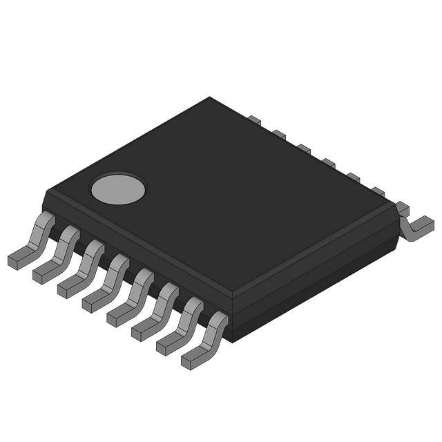
| 封装/外壳 | 16-TSSOP(0.173",4.40mm 宽) |
| 封装/箱体 | TSSOP-16 |
| 工作温度 | -40°C ~ 85°C |
| 工作电源电压 | 4.5 V to 5.5 V |
| 工作电源电流 | 10 mA |
| 工厂包装数量 | 2500 |
| 带LED驱动器 | 无 |
| 带定序器 | 无 |
| 带监控器 | 无 |
| 开关频率 | 200 kHz to 600 kHz |
| 拓扑 | 降压(降压)同步(1),线性(LDO)(1) |
| 描述/功能 | General Purpose PWM regulator and LDO controller |
| 最大工作温度 | + 85 C |
| 最小工作温度 | - 40 C |
| 标准包装 | 1 |
| 电压-电源 | 4.5 V ~ 5.5 V |
| 电压/电流-输出1 | 控制器 |
| 电压/电流-输出2 | 控制器 |
| 电压/电流-输出3 | - |
| 类型 | Current Mode PWM Controller |
| 系列 | FAN5069 |
| 绝缘 | Non-Isolated |
| 输入电压 | 3 V to 24 V |
| 输出数 | 2 |
| 输出电压 | 800 mV to 15 V |
| 输出类型 | Programmable |
| 频率-开关 | 200kHz |


- 商务部:美国ITC正式对集成电路等产品启动337调查
- 曝三星4nm工艺存在良率问题 高通将骁龙8 Gen1或转产台积电
- 太阳诱电将投资9.5亿元在常州建新厂生产MLCC 预计2023年完工
- 英特尔发布欧洲新工厂建设计划 深化IDM 2.0 战略
- 台积电先进制程称霸业界 有大客户加持明年业绩稳了
- 达到5530亿美元!SIA预计今年全球半导体销售额将创下新高
- 英特尔拟将自动驾驶子公司Mobileye上市 估值或超500亿美元
- 三星加码芯片和SET,合并消费电子和移动部门,撤换高东真等 CEO
- 三星电子宣布重大人事变动 还合并消费电子和移动部门
- 海关总署:前11个月进口集成电路产品价值2.52万亿元 增长14.8%


PDF Datasheet 数据手册内容提取
Is Now Part of To learn more about ON Semiconductor, please visit our website at www.onsemi.com Please note: As part of the Fairchild Semiconductor integration, some of the Fairchild orderable part numbers will need to change in order to meet ON Semiconductor’s system requirements. Since the ON Semiconductor product management systems do not have the ability to manage part nomenclature that utilizes an underscore (_), the underscore (_) in the Fairchild part numbers will be changed to a dash (-). This document may contain device numbers with an underscore (_). Please check the ON Semiconductor website to verify the updated device numbers. The most current and up-to-date ordering information can be found at www.onsemi.com. Please email any questions regarding the system integration to Fairchild_questions@onsemi.com. ON Semiconductor and the ON Semiconductor logo are trademarks of Semiconductor Components Industries, LLC dba ON Semiconductor or its subsidiaries in the United States and/or other countries. ON Semiconductor owns the rights to a number of patents, trademarks, copyrights, trade secrets, and other intellectual property. A listing of ON Semiconductor’s product/patent coverage may be accessed at www.onsemi.com/site/pdf/Patent-Marking.pdf. ON Semiconductor reserves the right to make changes without further notice to any products herein. ON Semiconductor makes no warranty, representation or guarantee regarding the suitability of its products for any particular purpose, nor does ON Semiconductor assume any liability arising out of the application or use of any product or circuit, and specifically disclaims any and all liability, including without limitation special, consequential or incidental damages. Buyer is responsible for its products and applications using ON Semiconductor products, including compliance with all laws, regulations and safety requirements or standards, regardless of any support or applications information provided by ON Semiconductor. “Typical” parameters which may be provided in ON Semiconductor data sheets and/or specifications can and do vary in different applications and actual performance may vary over time. All operating parameters, including “Typicals” must be validated for each customer application by customer’s technical experts. ON Semiconductor does not convey any license under its patent rights nor the rights of others. ON Semiconductor products are not designed, intended, or authorized for use as a critical component in life support systems or any FDA Class 3 medical devices or medical devices with a same or similar classification in a foreign jurisdiction or any devices intended for implantation in the human body. Should Buyer purchase or use ON Semiconductor products for any such unintended or unauthorized application, Buyer shall indemnify and hold ON Semiconductor and its officers, employees, subsidiaries, affiliates, and distributors harmless against all claims, costs, damages, and expenses, and reasonable attorney fees arising out of, directly or indirectly, any claim of personal injury or death associated with such unintended or unauthorized use, even if such claim alleges that ON Semiconductor was negligent regarding the design or manufacture of the part. ON Semiconductor is an Equal Opportunity/Affirmative Action Employer. This literature is subject to all applicable copyright laws and is not for resale in any manner.
F A N 5 0 September 2006 6 9 FAN5069 P W PWM and LDO Controller Combo M a n d Features Description L D ■ General Purpose PWM Regulator and LDO Controller The FAN5069 combines a high-efficiency Pulse-Width- O ■ Input Voltage Range: 3V to 24V Modulated (PWM) controller and an LDO (Low DropOut) C ■ Output Voltage Range: 0.8V to 15V linear regulator controller. Synchronous rectification pro- o vides high efficiency over a wide range of load currents. n – VCC Efficiency is further enhanced by using the low-side tr – 5V o ■ Shunt Regulator for 12V Operation MOSFET’s RDS(ON) to sense current. lle r ■ Support for Ceramic Cap on PWM Output Both the linear and PWM regulator soft-start are con- C ■ Programmable Current Limit for PWM Output trolled by a single external capacitor, to limit in-rush cur- o rent from the supply when the regulators are first m ■ Programmable Switching Frequency (200KHz to enabled. Current limit for PWM is also programmable. b 600KHz) o ■ R Current Sensing The PWM regulator employs a summing-current-mode DS(ON) control with external compensation to achieve fast load ■ Internal Synchronous Boot Diode transient response and provide design optimization. ■ Soft-Start for both PWM and LDO ■ Multi-Fault Protection with Optional Auto-restart FAN5069 is offered in both industrial temperature grade (-40°C to +85°C) as well as commercial temperature ■ 16-pin TSSOP Package grade (-10°C to +85°C). Applications ■ PC/Server Motherboard Peripherals – V (1.5V), V (1.5V) and CC_MCH DDQ V (1.25V) TT_GTL ■ Power Supply for – FPGA, DSP, Embedded Controllers, Graphic Card Processor, and Communication Processors ■ Industrial Power Supplies ■ High-Power DC-to-DC Converters Ordering Information Part Number Operating Temp. Range Pb-Free Package Packing Method Qty./Reel FAN5069MTCX -10°C to +85°C Yes 16-Lead TSSOP Tape and Reel 2500 FAN5069EMTCX -40°C to +85°C Yes 16-Lead TSSOP Tape and Reel 2500 Note: Contact Fairchild sales for availability of other package options. © 2005 Fairchild Semiconductor Corporation www.fairchildsemi.com FAN5069 Rev. 1.1.5
F A Typical Application N 5 0 RVCC 6 +12V 3 TO 24V 9 VCC 15 FAN5069 R(RAMP) R8 P 14 W +5V C9 M BOOT EN 11 a 7 n C3 SS C5 Q1 d 4 R4 ILIM 3 HDRV C4 C7 LD PWM 10 O R5 R(T) SW L1 PWM OUT 2 9 C AGND Q2 o 8 n PWM OUT 13LDRV R1 C6 tr o PGND l 12 l Q3 e GLDO FB r 16 6 C ULDO C2 C1 o LDO C O8UT R7 FBLDO 1 CONTROL 5 COMP R3 R2 mb R6 o Figure 1. Typical Application Diagram © 2005 Fairchild Semiconductor Corporation www.fairchildsemi.com FAN5069 Rev. 1.1.5 2
F A Pin Assignment N 5 0 FBLDO 1 16 GLDO 6 9 R(T) 2 15 VCC P ILIM 3 14 R(RAMP) W M SS 4 13 LDRV FAN5069 a n COMP 5 12 PGND d FB 6 11 BOOT L D EN 7 10 HDRV O C AGND 8 9 SW o n t Figure 2. Pin Assignment r o l l Pin Description e r C Pin # Name Description o m 1 FBLDO LDO Feedback. This node is regulated to VREF. b o 2 R(T) Oscillator Set Resistor. This pin provides oscillator switching frequency adjustment. By plac- ing a resistor (RT) from this pin to GND, the nominal 200kHz switching frequency is increased. 3 ILIM Current Limit. A resistor from this pin to GND sets the current limit. 4 SS Soft-Start. A capacitor from this pin to GND programs the slew rate of the converter and the LDO during initialization. It also sets the time by which the converter delays when restarting after a fault occurs. SS has to reach 1.2V before fault shutdown feature is enabled. The LDO is enabled when SS reaches 2.2V. 5 COMP COMP. The output of the error amplifier drives this pin. 6 FB Feedback. This pin is the inverting input of the internal error amplifier. Use this pin, in combi- nation with the COMP pin, to compensate the feedback loop of the converter. 7 EN Enable. Enables operation when pulled to logic high. Toggling EN resets the regulator after a latched fault condition. This is a CMOS input whose state is indeterminate if left open and needs to be properly biased at all times. 8 AGND Analog Ground. The signal ground for IC. All internal control voltages are referred to this pin. Tie this pin to the ground island/plane through the lowest impedance connection available. 9 SW Switching Node. Return for the high-side MOSFET driver and a current sense input. Connect to source of high-side MOSFET and drain of low-side MOSFET. 10 HDRV High-Side Gate Drive Output. Connect to the gate of the high-side power MOSFETs. This pin is also monitored by the adaptive shoot-through protection circuitry to determine when the high-side MOSFET is turned off. 11 BOOT Bootstrap Supply Input. Provides a boosted voltage to the high-side MOSFET driver. Connect to bootstrap capacitor as shown in Figure 1. 12 PGND Power Ground. The return for the low-side MOSFET driver. Connect to the source of the low- side MOSFET. 13 LDRV Low-Side Gate Drive Output. Connect to the gate of the low-side power MOSFETs. This pin is also monitored by the adaptive shoot-through protection circuitry to determine when the lower MOSFET is turned off. 14 R(RAMP) Ramp Resistor. A resistor from this pin to VIN sets the ramp amplitude and provides voltage feed-forward. 15 VCC VCC. Provides bias power to the IC and the drive voltage for LDRV. Bypass with a ceramic capacitor as close to this pin as possible. This pin has a shunt regulator which draws current when the input voltage is above 5.6V. 16 GLDO Gate Drive for the LDO. Turned off (low) until SS is greater than 2.2V. © 2005 Fairchild Semiconductor Corporation www.fairchildsemi.com FAN5069 Rev. 1.1.5 3
F A Absolute Maximum Ratings N 5 0 The “Absolute Maximum Ratings” are those values beyond which the safety of the device cannot be guaranteed. The 6 device should not be operated at these limits. The parametric values defined in the Electrical Characteristics tables are 9 not guaranteed at the absolute maximum ratings. The “Recommended Operating Conditions” table defines the condi- P tions for actual device operation. (1) W M Parameter Min. Max. Unit a n V to PGND 6.0 V CC d BOOT to PGND 33.0 V L D SW to PGND Continuous -0.5 33.0 V O Transient (t < 50nS, F < 500kHz) -3.0 33.0 V C o HDRV (V - – V ) 6.0 V n BOOT SW t r LDRV -0.5 6.0 V o l l All Other Pins -0.3 V + 0.3 V e CC r Maximum Shunt Current for V 150 mA C CC o Electrostatic Discharge Protection (ESD) HBM 3.5 kV m Level(2) b CDM 1.8 o Notes: 1. Stresses above those listed under “Absolute Maximum Ratings” may cause permanent damage to the device. This is a stress rating only; functional operation of the device at these or any conditions above those indicated in the operational section of this specification is not implied. Exposure to absolute maximum rating conditions for extended periods may affect device reliability. Absolute maximum ratings apply individually only, not in combination. Unless otherwise specified, all other voltages are referenced to AGND. 2. Using Mil Std. 883E, method 3015.7(Human Body Model) and EIA/JESD22C101-A (Charge Device Model). Thermal Information Symbol Parameter Min. Typ. Max. Unit T Storage Temperature -65 150 °C STG T Lead Soldering Temperature, 10 Seconds 300 °C L Vapor Phase, 60 Seconds 215 °C Infrared, 15 Seconds 220 °C P Power Dissipation, T = 25°C 715 mW D A θ Thermal Resistance, Junction-to-Case 37 °C/W JC θ Thermal Resistance, Junction-to-Ambient(3) 100 °C/W JA Notes: 3. Junction-to-ambient thermal resistance, θ , is a strong function of PCB material, board thickness, thickness and JA number of copper planes, number of vias used, diameter of vias used, available copper surface, and attached heat sink characteristics. Recommended Operating Conditions Symbol Parameter Conditions Min. Typ. Max. Unit V Supply Voltage V to GND 4.5 5.0 5.5 V CC CC Commercial -10 85 °C T Ambient Temperature A Industrial -40 85 °C T Junction Temperature 125 °C J © 2005 Fairchild Semiconductor Corporation www.fairchildsemi.com FAN5069 Rev. 1.1.5 4
F A Electrical Characteristics N 5 Unless otherwise noted, V = 5V, T = 25°C, using circuit in Figure 1. 0 CC A 6 9 The ‘•’ denotes that the specifications apply to the full ambient operating temperature range. See Notes 4 and 5. P Symbol Parameter Conditions Min. Typ. Max. Unit W M Supply Current a I V Current (Quiescent) HDRV, LDRV Open • 2.6 3.2 3.8 mA n VCC CC d I V Current (Shutdown) EN = 0V, V = 5.5V • 200 400 μA VCC(SD) CC CC L D I V Current (Operating) EN = 5V, V = 5.0V, 10 15 mA VCC(OP) CC CC O Q = 20nC, F = 200kHz FET SW C VSHUNT VCC Voltage(6) Sinking 1mA to 100mA at VCC 5.5 5.9 V o Pin n t r Under-Voltage Lockout (UVLO) o l l UVLO(H) Rising V UVLO Threshold • 4.00 4.25 4.50 V e CC r UVLO(L) Falling V UVLO Threshold • 3.60 3.75 4.00 V C CC o V UVLO Threshold 0.50 V m CC Hysteresis b o Soft-Start I Current 10 μA SS V LDO Start Threshold 2.2 V LDOSTART V PWM Protection Enable 1.2 V SSOK Threshold Oscillator F Frequency R(T) = 56KΩ ± 1% 240 300 360 KHz OSC R(T) = Open 160 200 240 KHz Frequency Range 160 600 KHz ΔV Ramp Amplitude R(RAMP) = 330KΩ 0.4 V RAMP (Peak-to-Peak) Minimum ON Time F = 200kHz 200 nS. Reference V Reference Voltage T = 0°C to 70°C • 790 800 810 mV REF A (Measured at FB Pin) T = -40°C to 85°C • 788 800 812 mV A Current Amplifier Reference 160 mV (at SW node) Error Amplifier DC Gain 80 dB GBWP Gain-BW Product 25 MHz S/R Slew Rate 10pF across COMP to GND 8 V/μS. Output Voltage Swing No Load • 0.5 4.0 V I FB Pin Source Current 1 μA FB Gate Drive R HDRV Pull-up Resistor Sourcing • 1.8 3.0 Ω HUP R HDRV Pull-down Resistor Sinking • 1.8 3.0 Ω HDN R LDRV Pull-up Resistor Sourcing • 1.8 3.0 Ω LUP R LDRV Pull-down Resistor Sinking • 1.2 2.0 Ω LDN © 2005 Fairchild Semiconductor Corporation www.fairchildsemi.com FAN5069 Rev. 1.1.5 5
F A Electrical Characteristics (Continued) N 5 0 Unless otherwise noted, V = 5V, T = 25°C, using circuit in Figure 1. CC A 6 9 The ‘•’ denotes that the specifications apply to the full ambient operating temperature range. See Notes 4 and 5. P W M Symbol Parameter Conditions Min. Typ. Max. Unit a Protection/Disable n d ILIM ILIMIT Source Current 9 10 11 μA L D I SW Pull-down Current SW = 1V, EN = 0V 2 mA SWPD O VUV Under-Voltage Threshold As % of set point; 2μS noise fil- • 65 75 80 % C ter o n V Over-Voltage Threshold As % of set point; 2μS noise fil- • 110 115 120 % t OV r ter o l l e TSD Thermal Shutdown 160 °C r C Enable Threshold Voltage Enable Condition • 2.0 V o Enable Threshold Voltage Disable Condition • 0.8 V m b Enable Source Current VCC = 5V 50 μA o LDO(7) V Reference Voltage (mea- T = 0°C to 70°C • 775 800 825 mV LDOREF A sured at FBLDO pin) T = -40°C to 85°C • 770 800 830 mV A Regulation 0A ≤ I ≤ 5A • 1.17 1.2 1.23 V LOAD V Drop out Voltage I ≤ 5A and R < 50mΩ 0.3 V LDO_DO LOAD DS-ON External Gate Drive V = 4.75V • 4.5 V CC V = 5.6V • 5.3 V CC Gate Drive Source Current 1.2 mA Gate Drive Sink Current 400 μA Notes: 4. All limits at operating temperature extremes are guaranteed by design, characterization, and statistical quality control. 5. AC specifications guaranteed by design/characterization (not production tested). 6. For a case when V is higher than the typical 5V V voltage observed at VCC pin when the internal shunt CC CC; regulator is sinking current to keep voltage on VCC pin constant. 7. Test Conditions: V = 1.5V and V = 1.2V LDO_IN LDO_OUT © 2005 Fairchild Semiconductor Corporation www.fairchildsemi.com FAN5069 Rev. 1.1.5 6
F A Typical Performance Characteristics N 5 0 6 9 P W M a n d L D O C o n t r o l l e r C o Figure 3. Dead Time Waveform Figure 6. PWM Load Transient (0 to 15A) m b o Figure 4. PWM Load Transient (0 to 5A) Figure 7. LDO Load Transient (0 to 2A) Figure 5. PWM Load Transient (0 to 10A) Figure 8. LDO Load Transient (0 to 5A) © 2005 Fairchild Semiconductor Corporation www.fairchildsemi.com FAN5069 Rev. 1.1.5 7
F A Typical Performance Characteristics (Continued) N 5 0 6 9 P W M a n d L D O C o n t r o l l e r C o Figure 9. PWM/LDO Power Up Figure 12. Enable ON (IPWM = 5A) m b o Figure 10. PWM/LDO Power Down Figure 13. Enable OFF (I = 5A) PWM Figure 11. Auto Restart © 2005 Fairchild Semiconductor Corporation www.fairchildsemi.com FAN5069 Rev. 1.1.5 8
F A Typical Performance Characteristics (Continued) N 5 0 6 9 PWM Line Regulation (VOUT = 1.5V) LDO Load Regulation (VOUT = 1.203V) P 1.210 W 1.54 M IL = 0A E (V) 1.52 IILL == 51A0A E (V)1.205 and G G A A L OLT 1.50 OLT1.200 DO V V T T U U C UTP 1.48 UTP1.195 VIN = 8V on O O VIN = 12V t 1.46 VVIINN == 1250VV rol l 1.190 e 6 8 10 12 14 16 18 20 0 1 2 3 4 5 r INPUT VOLTAGE (V) LOAD CURRENT (A) C o Figure 14. PWM Line Regulation Figure 17. LDO Load Regulation m b o Load Line Regulation (VOUT = 1.203V) Master Clock Frequency 1.210 700 IL = 0A IL = 2A 600 IL = 5A V) 1.205 GE ( Hz) 500 TA Y (k OL 1.200 NC 400 T V UE U Q P E 300 T R OU 1.195 F 200 1.190 100 8 10 12 14 16 18 20 0 100 200 300 400 INPUT VOLTAGE (V) RT (kΩ) Figure 15. LDO Line Regulation Figure 18. R vs. Frequency T PWM Load Regulation (VOUT = 1.50V) Efficiency vs. Input Voltage 1.510 100 VIN = 8V VIN = 12V VIN = 15V 80 AGE (V) 1.505 VIN = 20V Y (%) 60 VVVIIINNN === 811V25VV OLT 1.500 ENC VIN = 20V UT V FICI 40 TP EF U O 1.495 20 1.490 0 0 2 4 6 8 10 0 2 4 6 8 10 LOAD CURRENT (A) LOAD CURRENT (A) Figure 16. PWM Load Regulation Figure 19. 1.5V PWM Efficiency © 2005 Fairchild Semiconductor Corporation www.fairchildsemi.com FAN5069 Rev. 1.1.5 9
F A Block Diagram N 5 0 C 6 BOOT 9 Vcc Internal Vcc 5.6V Max. BOOT P Shunt Reg 10μA BoInotte Drnioadle W RILIM ILIM Current Limit M Comparator V IN a n d COMP PWM L Error PWM RQ D FB Amplifier Comparator HDRV O Vref S Adaptive C Gate Drive Vcc Circuit LO Vout on 10μA OSC SW C tro O SS ll e V CSeunrrseent LDRV r C IN RRAMP RGaemneprator Su mΣming Amplifier om R(RAMP) Amplifier PGND b o EN Enable Figure 20. Block Diagram Detailed Operation Description Choose a resistor such that: FAN5069 combines a high-efficiency, fixed-frequency ■ It is rated to handle the power dissipation. PWM controller designed for single-phase synchronous ■ Current sunk within the controller is minimized to buck Point-Of-Load converters with an integrated LDO prevent IC temperature rise. controller to support GTL-type loads. This controller is R Selection (IC) ideally suited to deliver low-voltage, high-current power VCC supplies needed in desktop computers, notebooks, The selection of R is dependent on: VCC workstations, and servers. The controller comes with an ■ Variation of the 12V supply integrated boot diode which helps reduce component ■ Gate charge of the top and bottom FETs (Q ) cost and increase space savings. With this controller, the FET ■ Switching frequency (F ) input to the power supply can be varied from 3V to 24V SW and the output voltage can be set to regulate at 0.8V to ■ Shunt regulator minimum current (1mA) 15V on the switcher output. The LDO output can be con- ■ Quiescent current of the IC (I ) Q figured to regulate between 0.8V to 3V and the input to the LDO can be from 1.5V to 5V, respectively. An internal Calculate R based on the minimum input voltage for VCC shunt regulator at the VCC pin facilitates the controller the V : CC operation from either a 5V or 12V power source. Vin –5.6 MIN (EQ. 1) R = ------------------------------------------------------------------------------------------ V Bias Supply VCC –3 CC (I +1•10 +Q •F •1.2) Q FET SW FAN5069 can be configured to operate from 5V or 12V For a typical example, where: Vin = 11.5V, I = 3mA, for V . When 5V supply is used for V , no resistor is MIN Q CC CC Q = 30nC, F = 300KHz, R is calculated to be required to be connected between the supply and the FET SW VCC 398.65Ω. V . When the 12V supply is used, a resistor R is CC VCC connected between the 12V supply and the V as PWM Section CC, shown in Figure 1. The internal shunt regulator at the The FAN5069’s PWM controller combines the conven- VCC pin is capable of sinking 150mA of current to tional voltage mode control and current sensing through ensure that the controller’s internal V is maintained at CC lower MOSFET R to generate the PWM signals. 5.6V maximum. DS_ON This method of current sensing is loss-less and cost effective. For more accurate current sense requirements, an optional external resistor can be connected with the bottom MOSFET in series. © 2005 Fairchild Semiconductor Corporation www.fairchildsemi.com FAN5069 Rev. 1.1.5 10
F A PWM Operation age varies. The R also has an effect on the current N RAMP limit, as can be seen in the R equation (EQ. 5). The 5 Refer to Figure 20 for the PWM control mechanism. The LIM 0 R value can be approximated using the following 6 FAN5069 uses the summing mode method of control to RAMP 9 equation: generate the PWM pulses. The amplified output of the P current-sense amplifier is summed with an internally W V –1.8 generated ramp and the combined signal is amplified R = ----------------I--N---------------------------KΩ M RAMP –8 and compared with the output of the error amplifier to get 6.3•10 •Fosc (EQ. 4) a the pulse width to drive the high-side MOSFET. The n d sensed current from the previous cycle is used to modu- L late the output of the summing block. The output of the where FOSC is in Hz. For example, for FOSC = 300kHz D summing block is also compared against the voltage and VIN = 12V, RRAMP ≈ 540KΩ. O threshold set by the RLIM resistor to limit the inductor cur- Gate Drive Section C rent on a cycle-by-cycle basis. The controller facilitates o n external compensation for enhanced flexibility. The adaptive gate control logic translates the internal t r PWM control signal into the MOSFET gate drive signals o Initialization and provides necessary amplification, level shifting, and ll e When the PWM is disabled, the SW node is connected shoot-through protection. It also has functions that help r C to GND through an internal 500Ω MOSFET to slowly dis- optimize the IC performance over a wide range of oper- o charge the output. As long as the PWM controller is ating conditions. Since the MOSFET switching time can m enabled, this internal MOSFET remains OFF. vary dramatically from device to device and with the b input voltage, the gate control logic provides adaptive o Soft-Start (PWM and LDO) dead time by monitoring the gate-to-source voltages of When V exceeds the UVLO threshold and EN is high, both upper and lower MOSFETs. The lower MOSFET CC the circuit releases SS and enables the PWM regulator. drive is not turned on until the gate-to-source voltage of The capacitor connected to the SS pin and GND is the upper MOSFET has decreased to less than approxi- charged by a 10µA internal current source, causing the mately 1V. Similarly, the upper MOSFET is not turned on voltage on the capacitor to rise. When this voltage until the gate-to-source voltage of the lower MOSFET exceeds 1.2V, all protection circuits are enabled. When has decreased to less than approximately 1V. This this voltage exceeds 2.2V, the LDO output is enabled. allows a wide variety of upper and lower MOSFETs to be The input to the error amplifier at the non-inverting pin is used without a concern for simultaneous conduction, or clamped by the voltage on the SS pin until it crosses the shoot-through. reference voltage. A low impedance path between the driver pin and the The time it takes the PWM output to reach regulation MOSFET gate is recommended for the adaptive dead- (T ) is calculated using the following equation: time circuit to work properly. Any delay along this path Rise reduces the delay generated by the adaptive dead-time –2 TRISE = 8×10 ×CSS (CSS is in μf) (EQ. 2) circuit, thereby increasing the chances for shoot-through. Oscillator Clock Frequency (PWM) Protection The clock frequency on the oscillator is set using an In the FAN5069, the converter is protected against external resistor, connected between R(T) pin and extreme overload, short-circuit, over-voltage, and under- ground. The frequency follows the graph, as shown in voltage conditions. All of these conditions generate an Figure 18. The minimum clock frequency is 200KHz, internal “fault latch” which shuts down the converter. For which is when R(T) pin is left open. Select the value of all fault conditions both the high-side and the low-side R(T) as shown in the equation below. This equation is drives are off except in the case of OVP where the low- valid for all FOSC > 200kHz. side MOSFET is turned on until the voltage on the FB pin goes below 0.4V. The fault latch can be reset either by 9 5×10 toggling the EN pin or recycling V to the chip. R(T) = ---------------------------------------------------Ω (EQ. 3) CC (F –200×103) OSC Over Current Limit (PWM) where F is in Hz. OSC The PWM converter is protected against overloading For example, for F = 300kHz, R(T) = 50KΩ. through a cycle-by-cycle current limit set by selecting OSC R resistor. An internal 10µA current source sets the ILIM threshold voltage for the output of the summing amplifier. R Selection and Feed-Forward Operation When the summing amplifier output exceeds this thresh- RAMP old level, the current limit comparator trips and the PWM The FAN5069 provides for input voltage feed-forward starts skipping pulses. If the current limit tripping occurs compensation through R . The value of R effec- RAMP RAMP for 16 continuous clock cycles, a fault latch is set and the tively changes the slope of the internal ramp, minimizing controller shuts down the converter. This shutdown fea- the variation of the PWM modulator gain when input volt- © 2005 Fairchild Semiconductor Corporation www.fairchildsemi.com FAN5069 Rev. 1.1.5 11
F A ture is disabled during the start-up until the voltage on N EN Pin PWM/Restart the SS capacitor crosses 1.2V. 5 0 Pull to GND OFF 6 To achieve current limit, the FAN5069 monitors the 9 inductor current during the OFF time by monitoring and VCC No restart after fault P holding the voltage across the lower MOSFET. The volt- Cap to GND Restart after TDELAY (Sec.) = W age across the lower MOSFET is sensed between the 0.85 x C where C is in μF M PGND and the SW pins. a n The output of the summing amplifier is a function of the The fault latch can also be reset by recycling the VCC to d inductor current, RDS_ON of the bottom FET and the gain the controller. L of the current sense amplifier. With the RDS_ON method Under Voltage Protection (PWM) DO of current sensing, the current limit can vary widely from unit to unit. R not only varies from unit to unit, but The PWM converter output is monitored constantly for C also has a tyDpSi_cOaNl junction temperature coefficient of under voltage at the FB pin. If the voltage on the FB pin on about 0.4%/°C (consult the MOSFET datasheet for stays lower than 75% of internal Vref for 16 clock cycles, tr actual values). The set point of the actual current limit the fault latch is set and the converter shuts down. This ol decreases in proportion to increase in MOSFET die tem- shutdown feature is disabled during startup until the volt- le r perature. A factor of 1.6 in the current limit set point typi- age on the SS capacitor reaches 1.2V. C cally compensates for all MOSFET RDS_ON variations, Over Voltage Protection (PWM) o m assuming the MOSFET's heat sinking keeps its operat- ing die temperature below 125°C. The PWM converter output voltage is monitored con- bo stantly at the FB pin for over voltage. If the voltage on the For more accurate current limit setting, use resistor FB pin stays higher than 115% of internal V for two REF sensing. In a resistor sensing scheme, an appropriate clock cycles, the controller turns OFF the upper MOS- current sense resistor is connected between the source FET and turns ON the lower MOSFET. This crowbar terminal of the bottom MOSFET and PGND. action stops when the voltage on the FB pin reaches Set the current limit by choosing R as follows: 0.4V to prevent the output voltage from becoming nega- ILIM tive. This over-voltage protection (OVP) feature is active as soon as the voltage on the EN pin becomes high. RILIM = 128+K-----1-----•----I--M----A----X----1•---.--R4---3-D----S---O----N-----•----1----0---3--+⎝⎜⎛⎝⎛1–V-1---.-i-8-n--⎠⎞•V-----o---F-u---St---•-W----3--•-3---R.--3--R-2---A--•--M---1-P--0---1---1--⎝⎜⎛ Turning ON the low-side MOSFETs on an OVP condition pulls down the output, resulting in a reverse current, (EQ. 5) which starts to build up in the inductor. If the output over- where R is in KΩ. voltage is due to failure of the high-side MOSFET, this ILIM crowbar action pulls down the input supply or blows its I is the maximum load current. MAX fuse, protecting the system, which is very critical. K1 is a constant to accommodate for the variation of During soft-start, if the output overshoots beyond 115% MOSFET R (typically 1.6). DS(ON) of V , the output voltage is brought down by the low- REF With K1 = 1.6, I = 20A, R = 7mΩ, V = 24V, side MOSFET until the voltage on the FB pin goes below MAX DS(ON) IN V = 1.5V, F = 300 KHz, R = 400 KΩ, R 0.4V. The fault latch is NOT set until the voltage on the OUT SW RAMP ILIM calculates to be 323.17KΩ. SS pin reaches 1.2V. Once the fault latch is set, the con- verter shuts down. Auto Restart (PWM) ILIM 115% Vref UV The FAN5069 supports two modes of response when the OV S Fault Q Latch internal fault latch is set. The user can configure it to Delay VSS>1.2VEN R FB 2 Clks keep the power supply latched in the OFF state OR in S the Auto Restart mode. When the EN pin is tied to V , Q CC the power supply is latched OFF. When the EN pin is ter- 0.4V R LS Drive minated with a 100nF to GND, the power supply is in Auto Restart mode. The table below describes the rela- Figure 21. Over-Voltage Protection tionship between PWM restart and setting on EN pin. Do Thermal Fault Protection not leave the EN pin open without any capacitor. The FAN5069 features thermal protection where the IC temperature is monitored. When the IC junction temper- ature exceeds +160°C, the controller shuts down and when the junction temperature gets down to +125°C, the converter restarts. © 2005 Fairchild Semiconductor Corporation www.fairchildsemi.com FAN5069 Rev. 1.1.5 12
F A LDO Section operate at the boundary of continuous and discontinuous N conduction modes. 5 The LDO controller is designed to provide ultra low volt- 0 6 ages, as low as 0.8V for GTL-type loads. The regulating Setting the Output Voltage (PWM) 9 loop employs a very fast response feedback loop and The internal reference for the PWM controller is at 0.8V. P small capacitors can be used to keep track of the chang- W The output voltage of the PWM regulator can be set in ing output voltage during transients. For stable opera- M the range of 0.8V to 90% of its power input by an exter- tion, the minimum capacitance on the output needs to be nal resistor divider. The output is divided down by an a 100µF and the typical ESR needs to be around 100mΩ. n external voltage divider to the FB pin (for example, R1 d The maximum voltage at the gate drive for the MOSFET and R as in Figure 24). The output voltage is given L BIAS can reach close to 0.5V below the VCC of the controller. by the following equation: DO For example, for a 1.2V output, the minimum enhance- m(4e.7n5t Vv-0o.l5taVg-e1 .2rVe q=u i3re.0d5 Vw)i.t hT h4e. 7d5roVp -oonu t VvoClCta gies fo3r.0 t5hVe VOUT = 0.8V×⎝⎛1+R-----RB----I1-A----S--⎠⎞ (EQ. 6) Con LDO is dependent on the load current and the MOSFET tr To minimize noise pickup on this node, keep the resistor o cvhooltasgeen . MItO iSs FrEeTcso mfomr etnhdee dL DtOo . uIsne alpopwli ceantihoannsc ewmheernet to GND (RBIAS) below 10KΩ. lle r LDO is not needed, pull up the FBLDO pin (Pin #1) Inductor Selection (PWM) C higher than 1V to disable the LDO. o When the ripple current, switching frequency of the con- m The soft-start on the LDO output (ramp) is controlled by verter, and the input-output voltages are established, b the capacitor on the SS pin to GND. The LDO output is select the inductor using the following equation: o enabled only when the voltage on the SS pin reaches V 2 2.2V. Refer to Figure 9 for start-up waveform. ⎛ OUT ⎞ V –-------------- ⎝ OUT V ⎠ IN Design Section LMIN = -----I------------------×-----F---------------- Ripple SW (EQ. 7) General Design Guidelines where I is the ripple current. Ripple Establishing the input voltage range and maximum cur- This number typically varies between 20% to 50% of the rent loading on the converter before choosing the switch- maximum steady-state load on the converter. ing frequency and the inductor ripple current is highly recommended. There are design trade-offs in choosing When selecting an inductor from the vendors, select the inductance value which is close to the value calculated at an optimum switching frequency and the ripple current. the rated current (including half the ripple current). The input voltage range should accommodate the worst- case input voltage with which the converter may ever Input Capacitor Selection (PWM) operate. This voltage needs to account for the cable drop The input capacitors must have an adequate RMS cur- encountered from the source to the converter. Typically, rent rating to withstand the temperature rise caused by the converter efficiency tends to be higher at lower input the internal power dissipation. The combined RMS cur- voltage conditions. rent rating for the input capacitor should be greater than When selecting maximum loading conditions, consider the value calculated using the following equation: the transient and steady-state (continuous) loading sep- arately. The transient loading affects the selection of the ⎛ V V 2⎞ OUT ⎛ OUT⎞ inductor and the output capacitors. Steady state loading IINPUT(RMS)=ILOAD(MAX)×⎝⎜ ---V-----I-N-----–⎝---V----I--N-----⎠ ⎠⎟ (EQ. 8) affects the selection of MOSFETs, input capacitors, and other critical heat-generating components. Common capacitor types used for such application The selection of switching frequency is challenging. include aluminum, ceramic, POS CAP, and OSCON. While higher switching frequency results in smaller com- Output Capacitor Selection (PWM) ponents, it also results in lower efficiency. Ideal selection of switching frequency takes into account the maximum The output capacitors chosen must have low enough operating voltage. The MOSFET switching losses are ESR to meet the output ripple and load transient require- directly proportional to FSW and the square function of ments. The ESR of the output capacitor should be lower the input voltage. than both of the values calculated below to satisfy both When selecting the inductor, consider the minimum and the transient loading and steady-state ripple conditions maximum load conditions. Lower inductor values pro- as given by the following equation: duce better transient response, but result in higher ripple V V STEP Ripple (EQ. 9) ESR≤---------------------------------- and ESR≤------------------- and lower efficiency due to high RMS currents. Optimum ΔI I LOAD(MAX) Ripple minimum inductance value enables the converter to © 2005 Fairchild Semiconductor Corporation www.fairchildsemi.com FAN5069 Rev. 1.1.5 13
F A In the case of aluminum and polymer based capacitors, N the output capacitance is typically higher than normally 5 VIN 0 required to meet these requirements. While selecting the 5V 6 9 ccaenra mbeic accahpieavceitdo rse afsoirl yt,h hei gohuetrp ucta; paaltchitoaungche lvoawlueer sE aSrRe CGD P R R W required to meet the VOUT(MIN) restrictions during a load D HDRV G GATE M transient. From the stability point of view, the zero caused by the ESR of the output capacitor plays an CGS an important role in the stability of the converter. SW d L Output Capacitor Selection (LDO) D Figure 23. Drive Equivalent Circuit O For stable operation, the minimum capacitance of 100µF The upper graph in Figure 22 represents Drain-to- C with ESR around 100mΩ is recommended. For other val- o Source Voltage (V ) and Drain Current (I ) waveforms. ues, contact the factory. DS D n The lower graph details Gate-to-Source Voltage (V ) t GS r Power MOSFET Selection (PWM) vs. time with a constant current charging the gate. The x- o l The FAN5069 is capable of driving N-Channel MOSFETs axis is representative of Gate Charge (QG). CISS = CGD le r as circuit switch elements. For better performance, + CGS and it controls t1, t2, and t4 timing. CGD receives C MOSFET selection must address these key parameters: the current from the gate driver during t3 (as VDS is fall- o ing). Obtain the gate charge (Q ) parameters shown on m G ■The maximum Drain-to-Source Voltage (VDS) should the lower graph from the MOSFET datasheets. b o be at least 25% higher than worst-case input voltage. Assuming switching losses are about the same for both ■The MOSFETs should have low Q , Q and Q G GD, GS. the rising edge and falling edge, Q1's switching losses ■The R of the MOSFETs should be as low as possible. DS_ON occur during the shaded time when the MOSFET has In typical applications for a buck converter, the duty voltage across it and current through it. cycles are lower than 20%. To optimize the selection of MOSFETs for both the high-side and low-side, follow dif- Losses are given by (EQ. 10), (EQ. 11), and (EQ. 12): ferent selection criteria. Select the high-side MOSFET to PUPPER = PSW + PCOND (EQ. 10) minimize the switching losses and the low-side MOSFET to minimize the conduction losses due to the channel ⎛VDS×IL ⎞ (EQ. 11) P = ---------------------×2×t F and the body diode losses. Note that the gate drive SW ⎝ 2 s⎠ SW losses also affect the temperature rise on the controller. V P = ⎛-----O----U---T--⎞ ×I2 ×R (EQ. 12) For loss calculation, refer to Fairchild's Application Note COND ⎝ V ⎠ OUT DS(ON) IN AN-6005 and the associated spreadsheet. where P is the upper MOSFET's total losses and UPPER High-Side Losses P and P are the switching and conduction losses SW COND for a given MOSFET. R is at the maximum junction Losses in the MOSFET can be understood by following DS(ON) temperature (T ) and t is the switching period (rise or the switching interval of the MOSFET in Figure 22. MOS- J S fall time) and equals t2+t3 (Figure 22.). FET gate drive equivalent circuit is shown in Figure 23. The driver's impedance and C determine t2 while t3's C C C ISS ISS GD ISS period is controlled by the driver's impedance and Q . V GD DS Since most of t occurs when V = V assume a con- S GS SP, stant current for the driver to simplify the calculation of t S using the following equation: Q Q t = -----G----(--S----W-----)≈------------------G----(--S----W-----)------------- (EQ. 13) s I V –V Driver ⎛ CC SP ⎞ ID ⎝R---------------------+-----R--------------⎠ Driver Gate Most MOSFET vendors specify Q and Q . Q GD GS G(SW) can be determined as: Q Q GS GD 4.5V QG(SW) = QGD + QGS – QTH where QTH is the gate charge required to reach the MOSFET threshold (V ). TH V SP Note that for the high-side MOSFET, V equals V , V DS IN TH QG(SW) which can be as high as 20V in a typical portable appli- V GS cation. Include the power delivered to the MOSFET's t1 t2 t3 t4 t5 (P ) in calculating the power dissipation required for GATE the FAN5069. Figure 22. Switching Losses and Q G © 2005 Fairchild Semiconductor Corporation www.fairchildsemi.com FAN5069 Rev. 1.1.5 14
F A PGATE is determined by the following equation: R-C components for the snubber are selected as follows: N 5 (EQ. 14) P = Q ×V ×F a) Measure the SW node ringing frequency (F ) with a 0 Gate G CC SW ring 6 low capacitance scope probe. 9 where QG is the total gate charge to reach VCC. b) Connect a capacitor (C ) from SW node to GND P Low-Side Losses SNUB W so that it reduces this ringing by half. M Q2 switches on or off with its parallel schottky diode simultaneously conducting, so the V ≈ 0.5V. Since c) Place a resistor (RSNUB) in series with this capacitor. a DS R is calculated using the following equation: n SNUB P is proportional to V , Q2's switching losses are d neSgWligible and Q2 is selecDteSd based on R alone. R = ----------------------2------------------------- (EQ. 17) L DS(ON) SNUB π×Fring×CSNUB D Conduction losses for Q2 are given by the equation: O 2 PCOND = (1–D)×IOUT×RDS(ON) (EQ. 15) d) Calculate the power dissipated in the snubber resistor C o where RDS(ON) is the RDS(ON) of the MOSFET at the as shown in the following equation: n hisi gthhee smt ionpimeruamtin dgu jtuyn ccytciolen ftoerm thpee rcaotunrvee ratenrd. D=VOUT/VIN PR(SNUB) = CSNUB×VI2N(MAX)×FSW (EQ. 18) trol where, VIN(MAX) is the maximum input voltage and FSW le Since DMIN < 20% for portable computers, (1-D) ≈ 1 pro- is the converter switching frequency. r C duces a conservative result, simplifying the calculation. The snubber resistor chosen should be de-rated to han- o m The maximum power dissipation (PD(MAX)) is a function dle the worst-case power dissipation. Do not use wire- b of the maximum allowable die temperature of the low- wound resistors for RSNUB. o side MOSFET, the θ and the maximum allowable JA, ambient temperature rise. P is calculated using Loop Compensation D(MAX) the following equation: Typically, the closed loop crossover frequency (F ), cross T –T where the overall gain is unity, should be selected to PD(MAX) = ----J---(--M----A----X---)-θ-----------A---(--M----A----X----) (EQ. 16) achieve optimal transient and steady-state response to JA disturbances in line and load conditions. It is recom- θ depends primarily on the amount of PCB area JA mended to keep F below fifth of the switching fre- cross devoted to heat sinking. quency of the converter. Higher phase margin tends to Selection of MOSFET Snubber Circuit have a more stable system with more sluggish response to load transients. Optimum phase margin is about 60°, a The Switch node (SW) ringing is caused by fast switch- good compromise between steady state and transient ing transitions due to the energy stored in the parasitic responses. A typical design should address variations elements. This ringing on the SW node couples to other over a wide range of load conditions and over a large circuits around the converter if they are not handled sample of devices. properly. To dampen this ringing, an R-C snubber is con- nected across the SW node and the source of the low- side MOSFET. V IN Current Sense Q1 V Amplifier IN R RAMP Ramp Generator PWM L RDC VOUT Summing & Σ DRIVER C Amplifier Q2 RL R ES C2 C1 R2 C3 R3 R BIAS R1 Reference Figure 24. Closed-Loop System with Type-3 Network © 2005 Fairchild Semiconductor Corporation www.fairchildsemi.com FAN5069 Rev. 1.1.5 15
F A FAN5069 has a high gain error amplifier around which For further information about Type-2 compensation N the loop is closed. Figure 24 shows a Type-3 compensa- networks, refer to: 5 0 tion network. For Type-2 compensation, R3 and C3 are 6 ■ Venable, H. Dean, "The K factor: A new mathematical 9 not used. Since the FAN5069 architecture employs sum- tool for stability analysis and synthesis,” Proceedings ming current mode, Type-2 compensation can be used P of Powercon, March 1983. W for most applications. M Note: For critical applications requiring wide loop a bandwidth using very low ESR output capacitors, n d use Type-3 compensation. L D O Type 3 Feedback Component Calculations C Use the following steps to calculate feedback components: o n Notation: t r o C = Net Output Filter capacitance l 0 le Gp(s) =Net Gain of Plant = control-to-output transfer function r C L = Inductor Value o m R = ON-state Drain-to Source Resistance of Low-side MOSFET b DSON o R = Net ESR of the Output Filter Capacitors es R = Load Resistance L T = Switching Period s V = Input Voltage IN F = Switching Frequency SW Equations: Effective current sense resistance = R = 7×R (EQ. 19) i DSON R L Current modulator DC gain = M = ------- (EQ. 20) i R i (V –1.8)×T Effective ramp amplitude = V = 3.33×10¹⁰×-------I--N------------------------------s-- m R ramp (EQ. 21) V IN Voltage modulator DC gain = M = --------- (EQ. 22) v V m M ×M Plant DC gain = M = M ||M = ------v--------------i (EQ. 23) o v i M +M v i π Sampling gain natural frequency = ω = ------ (EQ. 24) n T s –2 Sampling gain quality factor (damping) = Q = ------ (EQ. 25) z π M M ×R O ⎛ v i⎞ Effective inductance = L = --------× L+-------------------- (EQ. 26) e M ⎝ ω ×Q ⎠ v n z M ×R ×R R = ------v-------------i------------L-- = (M ×R)||R (EQ. 27) p M ×R +R v i L v i L © 2005 Fairchild Semiconductor Corporation www.fairchildsemi.com FAN5069 Rev. 1.1.5 16
F A Poles and Zeros of Plant Transfer Function: N 5 1 0 Plant zero frequency = f = ------------------------------------------ (EQ. 28) 6 z 2×π×Co×Res 9 P Plant 1st pole frequency = f = ----------------------------1------------------------------- (EQ. 29) W p1 ⎛ Le⎞ M 2×π× C ×R +------- ⎝ o p RL⎠ a n d Plant 2nd pole frequency = f = -----1-------×⎛---------1-----------+R-----p--⎞ (EQ. 30) L p2 2×π ⎝C ×R L ⎠ D o L e O Plant 3rd pole frequency = fp3 = 2----ω-×---n2--π--×---×--L---R-e----- (EQ. 31) Co p n t r o Plant gain (magnitude) response: l l e ⎛f⎞2 r 1+ ---- ⎝f ⎠ C G (f) = 20×logM +10×log ---------------------------------------------------------z------------------------------------------------- (EQ. 32) o p 0 ⎛ f ⎞2 ⎛ f ⎞2 ⎛ f ⎞2 m 1+ ------- × 1+ ------- × 1+ ------- ⎝f ⎠ ⎝f ⎠ ⎝f ⎠ b p1 p2 p3 o Plant phase response: ∠G (f) = tan–1⎛--f--⎞ –tan–1⎛---f----⎞ –tan–1⎛---f----⎞ ––tan–1⎛---f----⎞ (EQ. 33) P ⎝f ⎠ ⎝f ⎠ ⎝f ⎠ ⎝f ⎠ z p1 p2 p3 Choose R1, R to set the output voltage using EQ.6. Choose the zero crossover frequency F of the overall BIAS cross loop. Typically F should be less than fifth of F . Choose the desired phase margin; typically between 60° to 90°. cross sw Calculate plant gain at F using EQ.34 by substituting F in place of f. The gain that the amplifier needs to pro- cross cross vide to get the required crossover is given by: 1 G = -------------------------------- (EQ. 34) AMP G (F ) p cross The phase boost required is calculated as given in (EQ. 35) Phase Boost= M–∠G (F )–90° (EQ. 35) P cross where M is the desired phase margin in degrees. The feedback component values are calculated as given in equations below: 2 ⎧ ⎛Boost⎞ ⎫ K = ⎨Tan ⎝-------4---------⎠ +45 ⎬ ⎩ ⎭ (EQ. 36) 1 C2= ------------------------------------------------------------------------ 2×π×F ×G ×R1 cross AMP (EQ. 37) C1 = C2×(K–1) (EQ. 38) 1 C3= ---------------------------------------------------------------- (EQ. 39) 2×π×F × K×R3 cross K R2= -------------------------------------------------- (EQ. 40) 2×π×F ×C1 cross R1 R3= ------------------ (EQ. 41) (K–1) © 2005 Fairchild Semiconductor Corporation www.fairchildsemi.com FAN5069 Rev. 1.1.5 17
F A Design Tools Layout Considerations N 5 Fairchild application note AN-6010 provides a PSPICE The switching power converter layout needs careful 0 6 model and spreadsheet calculator for the PWM regula- attention and is critical to achieving low losses and clean 9 tor, simplifying external component selections and verify- and stable operation. Below are specific recommenda- P ing loop stability. The topics covered provide an tions for good board layout: W understanding of the calculations in the spreadsheet. M ■ Keep the high-current traces and load connections as The spreadsheet calculator, which is part of AN-6010, short as possible. a n can be used to calculate all external component values ■ Use thick copper boards whenever possible to d for designing around FAN5069. The spreadsheet pro- achieve higher efficiency. L vides optimized compensation components and gener- ■ Keep the loop area between the SW node, low-side DO ates a Bode Plot to ensure loop stability. MOSFET, inductor, and the output capacitor as small C Based on the input values entered, AN-6010’s PSPICE as possible. o n model can be used to simulate Bode Plots (for loop sta- ■ Route high dV/dt signals, such as SW node, away t bility) as well as transient analysis to help customize the from the error amplifier input/output pins. Keep com- ro design for a wide range of applications. ponents connected to these pins close to the pins. ll e ■ Place ceramic de-coupling capacitors very close to the r Use Fairchild Application Note AN-6005 for prediction of C VCC pin. the losses and die temperatures for the power semicon- o ductors used in the circuit. ■ All input signals are referenced with respect to AGND m pin. Dedicate one layer of the PCB for a GND plane. b AN-6010 and AN-6005 can be downloaded from o Use at least four layers for the PCB. www.fairchildsemi.com/apnotes/. ■ Minimize GND loops in the layout to avoid EMI-related issues. ■ Use wide traces for the lower gate drive to keep the drive impedances low. ■ Connect PGND directly to the lower MOSFET source pin. ■ Use wide land areas with appropriate thermal vias to effectively remove heat from the MOSFETs. ■ Use snubber circuits to minimize high-frequency ring- ing at the SW nodes. ■ Place the output capacitor for the LDO close to the source of the LDO MOSFET. © 2005 Fairchild Semiconductor Corporation www.fairchildsemi.com FAN5069 Rev. 1.1.5 18
F A Application Board Schematic N 5 0 V = 3 to 24V; V =1.5V at 20A. IN OUT 6 9 +5V or +12V Vcc J1 P W R9 220 M PWM OUT Q1 0.2C2µ7F 15 VCC U1R(RAMP) 14 R6 453K FDD6296 C6 C10 + C11+3-24V VJ2IN and L LDO FDD6530A 16 GLDO HDRV 10 Q2 0.1µF 820µF 820µF GJ3ND DO LDO_OJJu67t 0C.41µF +5C6107µF 5RK8R710K R4 12 FRB(TL)DO BOSOWT 191 0.C228µF L1 1.8µH PWM OUT SJ4W_Out Contr GND 5204RK3C5K5 TP1 34 ISLSIM PLGDNRDV 1132 QFD3D6606 FDD6606 Q4 2R3C.12.1136nF 560Cµ1F2 +560Cµ1F3+560Cµ1F4 +0.1Cµ1F5 GJ5ND oller Co 0.1µF C1 m TP2 C9 0.01µF 7 EN COMP 5 C21500pF 12R.72k 82R53 330C03pF bo 8 AGND FB 6 220pF R1 5.11K FAN5069 R10 5.83K Figure 25. Application Board Schematic Bill of Materials Part Description Quantity Designator Vendor Vendor Part # Capacitor, 1500pF, 20%, 25V, 0603,X7R 1 C1 Panasonic PCC1774CT-ND Capacitor, 220pF, 5%, 50V, 0603,NPO 1 C2 Panasonic PCC221ACVCT-ND Capacitor, 3300pF, 10%, 50V, 0603,X7R 1 C3 Panasonic PCC1778CT-ND Capacitor, 0.1µF, 10%, 25V, 0603,X7R 4 C4, C5, C6, C15 Panasonic PCC2277CT-ND Capacitor, 0.22µF, 20%, 25V, 0603,X7R 2 C7, C8 Panasonic PCC1767CT-ND Capacitor, 0.01µF, 10%, 50V, 0603,X7R 1 C9 Panasonic PCC1784CT-ND Capacitor, 820µF, 20%, 10X20, 25V,20mOhm,1.96A 2 C10, C11 Nippon-Chemicon KZH25VB820MHJ20 Capacitor, 820µF, 20%, 8X8, 2.5V,7mOhm,6.1A 1 C17 Nippon-Chemicon PSC2.5VB820MH08 Capacitor, 560µF, 20%, 8X11.5, 4V,7mOhm,5.58A 3 C12, C13, C14 Nippon-Chemicon PSA4VB560MH11 Capacitor, 3300pF, 10%, 50V, 0603,X7R 1 C16 Panasonic PCC332BNCT-ND Connector Header 0.100 Vertical, Tin - 2 Pin 1 J1 Molex WM6436-ND Terminal Quickfit Male .052"Dia.187" Tab 6 J2 - J7 Keystone 1212K-ND Inductor, 1.8µH, 20%, 26Amps Max, 3.24mOhm 1 L1 Inter-Technical SC5018-1R8M MOSFET N-CH, 32 mΩ, 20V, 21A, D-PAK, FSID: FDD6530A 1 Q1 Fairchild Semiconductor FDD6530A MOSFET N-CH, 8.8 mΩ, 30V, 50A, D-PAK, FSID: FDD6296 1 Q2 Fairchild Semiconductor FDD6296 MOSFET N-CH, 6 mΩ, 30V, 75A, D-PAK, FSID: FDD6606 2 Q3, Q4 Fairchild Semiconductor FDD6606 Resistor, 5.11K, 1%, 1/16W 1 R1 Panasonic P5.11KHCT-ND Resistor, 12.7K, 1%, 1/16W 1 R2 Panasonic P12.7KHCT-ND Resistor, 825Ω, 1%, 1/16W 1 R3 Panasonic P825HCT-ND Resistor, 49.9K, 1%, 1/16W 1 R4 Panasonic P49.9KHCT-ND Resistor, 243K, 1%, 1/16W 1 R5 Panasonic P243KHCT-ND Resistor,453K, 1%, 1/16W 1 R6 Panasonic P453KHCT-ND Resistor,10K, 1%, 1/16W 1 R7 Panasonic P10.0KHCT-ND Resistor, 4.99K, 1%, 1/16W 1 R8 Panasonic P4.99KHCT-ND Resistor, 220Ω, 1%, 1/4W 1 R9 Panasonic P200FCT-ND Resistor, 5.90K, 1%, 1/16W 1 R10 Panasonic P5.90KHCT-ND Resistor, 2.2Ω, 1%, 1/4W 1 R11 Panasonic P2.2ECT-ND Connector Header 0.100 Vertical, Tin - 1 Pin 3 TP1,TP2, Vcc Molex WM6436-ND IC, System Regulator, TSSOP16, FSID: FAN5069 1 U1 Fairchild Semiconductor FAIRCHILD © 2005 Fairchild Semiconductor Corporation www.fairchildsemi.com FAN5069 Rev. 1.1.5 19
F A Typical Application Board Layout N 5 0 6 9 P W M a n d L D O C o n t r o l l e Figure 26. Assembly Diagram Figure 29. Mid Layer 2 r C o m b o Figure 27. Top Layer Figure 30. Bottom Layer Figure 28. Mid Layer 1 © 2005 Fairchild Semiconductor Corporation www.fairchildsemi.com FAN5069 Rev. 1.1.5 20
5.10 A 4.90 4.55 16 9 B 4.50 6.4 5.90 4.45 7.35 4.30 0.65 3.2 1.45 1 PIN #1 8 0.2 C B A 0.11 IDENT ALL LEAD TIPS 5.00 TOP VIEW LAND PATTERN RECOMMENDATION 1.10 MAX 0.15 A 0.05 0.20 0.09 0.90 ALL LEAD TIPS 0.1 C 0.30 C 0.19 SIDE VIEW 0.13 M A B S C S 0.65 NOTES: FRONT VIEW A. CONFORMS TO JEDEC REGISTRATION 12° MO-153, VARIATION AB TOP & BOTTOM B. ALL DIMENSIONS ARE IN MILLIMETERS GAGE C. DIMENSIONS ARE EXCLUSIVE OF PLANE BURRS, MOLD FLASH, AND TIE BAR 0.25 EXTRUSIONS 8° D. DIMENSIONS AND TOLERANCES 0° PER ASME Y14.5M, 2009 E. LAND PATTERN RECOMMENDATION PER IPC7351 - ID# TSOP65P640X110-16N 0.70 F. DRAWING FILENAME: MKT-MTC16rev5 0.50 SEATING PLANE DETAIL A SCALE 3:1
ON Semiconductor and are trademarks of Semiconductor Components Industries, LLC dba ON Semiconductor or its subsidiaries in the United States and/or other countries. ON Semiconductor owns the rights to a number of patents, trademarks, copyrights, trade secrets, and other intellectual property. A listing of ON Semiconductor’s product/patent coverage may be accessed at www.onsemi.com/site/pdf/Patent−Marking.pdf. ON Semiconductor reserves the right to make changes without further notice to any products herein. ON Semiconductor makes no warranty, representation or guarantee regarding the suitability of its products for any particular purpose, nor does ON Semiconductor assume any liability arising out of the application or use of any product or circuit, and specifically disclaims any and all liability, including without limitation special, consequential or incidental damages. Buyer is responsible for its products and applications using ON Semiconductor products, including compliance with all laws, regulations and safety requirements or standards, regardless of any support or applications information provided by ON Semiconductor. “Typical” parameters which may be provided in ON Semiconductor data sheets and/or specifications can and do vary in different applications and actual performance may vary over time. All operating parameters, including “Typicals” must be validated for each customer application by customer’s technical experts. ON Semiconductor does not convey any license under its patent rights nor the rights of others. ON Semiconductor products are not designed, intended, or authorized for use as a critical component in life support systems or any FDA Class 3 medical devices or medical devices with a same or similar classification in a foreign jurisdiction or any devices intended for implantation in the human body. Should Buyer purchase or use ON Semiconductor products for any such unintended or unauthorized application, Buyer shall indemnify and hold ON Semiconductor and its officers, employees, subsidiaries, affiliates, and distributors harmless against all claims, costs, damages, and expenses, and reasonable attorney fees arising out of, directly or indirectly, any claim of personal injury or death associated with such unintended or unauthorized use, even if such claim alleges that ON Semiconductor was negligent regarding the design or manufacture of the part. ON Semiconductor is an Equal Opportunity/Affirmative Action Employer. This literature is subject to all applicable copyright laws and is not for resale in any manner. PUBLICATION ORDERING INFORMATION LITERATURE FULFILLMENT: N. American Technical Support: 800−282−9855 Toll Free ON Semiconductor Website: www.onsemi.com Literature Distribution Center for ON Semiconductor USA/Canada 19521 E. 32nd Pkwy, Aurora, Colorado 80011 USA Europe, Middle East and Africa Technical Support: Order Literature: http://www.onsemi.com/orderlit Phone: 303−675−2175 or 800−344−3860 Toll Free USA/Canada Phone: 421 33 790 2910 Fax: 303−675−2176 or 800−344−3867 Toll Free USA/Canada Japan Customer Focus Center For additional information, please contact your local Email: orderlit@onsemi.com Phone: 81−3−5817−1050 Sales Representative © Semiconductor Components Industries, LLC www.onsemi.com www.onsemi.com 1