ICGOO在线商城 > F951A476MSAAQ2
 Datasheet下载
- 型号: F951A476MSAAQ2
- 制造商: AVX
- 库位|库存: xxxx|xxxx
- 要求:
| 数量阶梯 | 香港交货 | 国内含税 |
| +xxxx | $xxxx | ¥xxxx |
查看当月历史价格
查看今年历史价格
F951A476MSAAQ2产品简介:
ICGOO电子元器件商城为您提供F951A476MSAAQ2由AVX设计生产,在icgoo商城现货销售,并且可以通过原厂、代理商等渠道进行代购。 提供F951A476MSAAQ2价格参考以及AVXF951A476MSAAQ2封装/规格参数等产品信息。 你可以下载F951A476MSAAQ2参考资料、Datasheet数据手册功能说明书, 资料中有F951A476MSAAQ2详细功能的应用电路图电压和使用方法及教程。
| 参数 | 数值 |
| 产品目录 | |
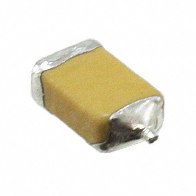
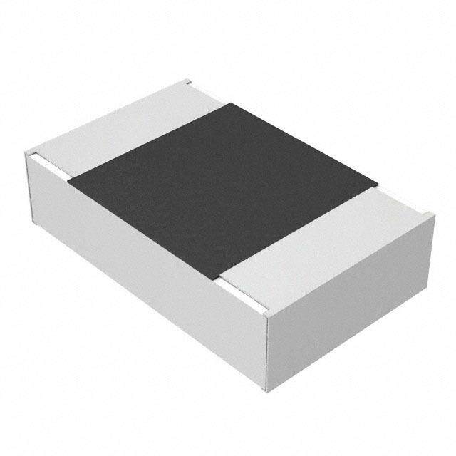
| 描述 | CAP TANT 47UF 10V 20% 1206钽质电容器-固体SMD 10volts 47uF 3.2x1.5 |
| ESR | 1.1 Ohms |
| ESR(等效串联电阻) | 1.1 欧姆 |
| 产品分类 | |
| 品牌 | AVX |
| 产品手册 | |
| 产品图片 |
|
| rohs | 符合RoHS无铅 / 符合限制有害物质指令(RoHS)规范要求 |
| 产品系列 | 钽电容器,钽质电容器-固体SMD,AVX F951A476MSAAQ2F95 Frameless™ |
| 数据手册 | |
| 产品型号 | F951A476MSAAQ2 |
| PCN制造商信息 | |
| 不同温度时的使用寿命 | - |
| 产品 | Tantalum Solid Standard Grade - Other Various |
| 产品种类 | 钽质电容器-固体SMD |
| 其它名称 | 478-8446-1 |
| 制造商尺寸代码 | S |
| 制造商库存号 | S Case |
| 包装 | 剪切带 (CT) |
| 商标 | AVX |
| 商标名 | FRAMELESS |
| 外壳代码-in | 1206 |
| 外壳代码-mm | 3216 |
| 外壳宽度 | 1.6 mm |
| 外壳长度 | 3.2 mm |
| 大小/尺寸 | 0.126" 长 x 0.063" 宽(3.20mm x 1.60mm) |
| 安装类型 | 表面贴装 |
| 容差 | 20 % |
| 封装 | Reel |
| 封装/外壳 | 1206(3216 公制) |
| 封装/箱体 | 1206 (3216 metric) |
| 工作温度 | -55°C ~ 125°C |
| 工作温度范围 | - 55 C to + 125 C |
| 工厂包装数量 | 2500 |
| 引线间距 | - |
| 损耗因数DF | 14 |
| 标准包装 | 1 |
| 特性 | 通用 |
| 电压-额定 | 10V |
| 电压额定值 | 10 V |
| 电容 | 47 uF |
| 端接类型 | SMD/SMT |
| 类型 | 保形涂层 |
| 系列 | F95 |
| 高度 | 1 mm |
| 高度-安装(最大值) | 0.063"(1.60mm) |


- 商务部:美国ITC正式对集成电路等产品启动337调查
- 曝三星4nm工艺存在良率问题 高通将骁龙8 Gen1或转产台积电
- 太阳诱电将投资9.5亿元在常州建新厂生产MLCC 预计2023年完工
- 英特尔发布欧洲新工厂建设计划 深化IDM 2.0 战略
- 台积电先进制程称霸业界 有大客户加持明年业绩稳了
- 达到5530亿美元!SIA预计今年全球半导体销售额将创下新高
- 英特尔拟将自动驾驶子公司Mobileye上市 估值或超500亿美元
- 三星加码芯片和SET,合并消费电子和移动部门,撤换高东真等 CEO
- 三星电子宣布重大人事变动 还合并消费电子和移动部门
- 海关总署:前11个月进口集成电路产品价值2.52万亿元 增长14.8%


PDF Datasheet 数据手册内容提取
Conformal Coated Tantalum Chip F95 Series – Standard FEATURES APPLICATIONS • Compliant to the RoHS2 directive 2011/65/EU • Smartphone • For high frequency • Tablet PC • SMD Conformal • Wireless module • Small and high CV • e-book LEAD-CFOREMEP COONMENPATTIBLE CASE DIMENSIONS: millimeters (inches) EIA EIA L W Code L W H A B C D* Code Metric A 1207 32 17-16 3.20±0.30 1.70±0.30 1.40±0.20 0.80±0.30 1.20±0.30 0.80±0.30 0.20 H (0.126±0.012) (0.067±0.012) (0.055±0.008) (0.031±0.012) (0.047±0.012) (0.031±0.012) (0.008) Resin 3.50±0.20 2.80±0.20 1.80±0.20 0.80±0.30 1.20±0.30 1.10±0.30 0.20 B 1411 3528-20 (0.138±0.008) (0.110±0.008) (0.071±0.008) (0.031±0.012) (0.047±0.012) (0.043±0.012) (0.008) 2.20±0.30 1.25±0.30 1.00±0.20 0.60±0.30 0.80±0.30 0.80±0.30 0.20 P 0905 2212-12 (0.087±0.012) (0.049±0.012) (0.039±0.008) (0.024±0.012) (0.031±0.012) (0.031±0.012) (0.008) Solderelectrode Solderelectrode 3.20±0.20 1.60±0.20 0.80±0.20 0.80±0.20 1.20±0.20 0.80±0.20 0.20 Q 1306 3216-10 (0.126±0.008) (0.063±0.008) (0.031±0.008) (0.031±0.008) (0.047±0.008) (0.031±0.008) (0.008) (D) A B C 2.20±0.30 1.25±0.30 0.65 max. 0.60±0.30 0.80±0.30 0.50 min. 0.20 R 0905 2212-065 (0.087±0.012) (0.049±0.012) (0.026 max.) (0.024±0.012) (0.031±0.012) (0.020 min.) (0.008) Single-side electrodes (Both electrodes at bottom side only) 3.20±0.30 1.60±0.30 1.00±0.20 0.80±0.30 1.20±0.30 0.80±0.30 0.20 S 1306 3216-12 (0.126±0.012) (0.063±0.012) (0.039±0.008) (0.031±0.012) (0.047±0.012) (0.031±0.012) (0.008) 3.50±0.20 2.70±0.20 1.00±0.20 0.80±0.20 1.20±0.20 1.10±0.30 0.20 T 1411 3527-12 (0.138±0.008) (0.106±0.008) (0.039±0.008) (0.031±0.008) (0.047±0.008) (0.043±0.012) (0.008) *D dimension only for reference HOW TO ORDER F95 0G 337 M A AQ2 or Q2 Type Rated Capacitance Code Tolerance Case Packaging Specification Suffix Single Face Voltage pF code: 1st two digits K=±10% Size See Tape & Reel LZT = Rated temperature Electrode represent significant M=±20% See Packaging Section 60ºC only figures, 3rd digit represents table multiplier (number of zeros above to follow) TECHNICAL SPECIFICATIONS Category Temperature Range: -55 to +125°C Rated Temperature: +85°C Capacitance Tolerance: ±20%, ±10% at 120Hz Dissipation Factor: Refer to next page ESR 100kHz: Refer to next page Leakage Current: Refer to next page Provided that: After 1 minute’s application of rated voltage, leakage current at 85°C 10 times or less than 20ºC specified value. After 1 minute’s application of rated voltage, leakage current at 125°C 12.5 times or less than 20ºC specified value. Capacitance Change By Temperature +15% Max. at +125°C +10% Max. at +85°C -10% Max. at -55°C 166 The Important Information/Disclaimer is incorporated in these specifications by reference and should be reviewed in full before placing any order. 071119
Conformal Coated Tantalum Chip F95 Series – Standard CAPACITANCE AND RATED VOLTAGE RANGE (LETTER DENOTES CASE SIZE) Capacitance Rated Voltage μF Code 4V (0G) 6.3V (0J) 10V (1A) 16V (1C) 20V (1D) 25V (1E) 35V (1V) 50V (1H) 1.0 105 R P/S P(M)* 1.5 155 2.2 225 P P/R A 3.3 335 4.7 475 P/R A/S A/P/Q/S B 6.8 685 10 106 P/R(M) A/P/Q/S A/B/S A/B 15 156 P A/S 22 226 R(M) A/P(M)/Q/S A/B/Q/S/T B 33 336 P(M) A/P(M)/Q/S B/T B 47 476 P(M) A/B/P(M)/S/T B 68 686 P(M) B 100 107 A/P/S A/B/P(M)/Q/S/T A/B/T 150 157 B/P(M) B 220 227 A/B/Q/S/T B 330 337 A/B/T B 470 477 B B 680 687 Released ratings (M tolerance only) Please contact to your local AVX sales office when these series are being designed in your *Rated temperature 60°C only. Please contact AVX when you need detail spec. application. RATINGS & PART NUMBER REFERENCE Rated DF @ ESR @ 100kHz RMS Current (mA) *1 AVX Case Capacitance DCL Voltage 120Hz 100kHz ΔC/C MSL Part No. Size (μF) (μA) 25ºC 60ºC 85ºC 125ºC (V) (%) (Ω) (%) 4 Volt F950G107#AAAQ2 A 100 4 4.0 12 0.5 387 – 349 155 * 3 F950G107#PAAQ2 P 100 4 4.0 30 1.2 158 – 142 63 ±15 3 F950G107#SAAQ2 S 100 4 4.0 14 0.8 274 – 246 110 * 3 F950G157#BAAQ2 B 150 4 6.0 14 0.4 461 – 415 184 * 3 F950G157MPAAQ2 P 150 4 12.0 31 1.1 165 – 149 66 ±20 3 F950G227#AAAQ2 A 220 4 8.8 25 0.8 306 – 276 122 ±15 3 F950G227#BAAQ2 B 220 4 8.8 16 0.4 461 – 415 184 * 3 F950G227#QAAQ2 Q 220 4 8.8 30 1.5 173 – 156 69 ±20 3 F950G227#SAAQ2 S 220 4 8.8 30 0.8 274 – 246 110 ±15 3 F950G227#TAAQ2 T 220 4 8.8 25 0.6 365 – 329 146 * 3 F950G337#AAAQ2 A 330 4 13.2 40 0.8 306 – 276 122 ±20 3 F950G337#BAAQ2 B 330 4 13.2 30 0.6 376 – 339 151 ±15 3 F950G337#TAAQ2 T 330 4 13.2 40 0.8 316 – 285 126 ±20 3 F950G477#BAAQ2 B 470 4 18.8 40 0.4 461 – 415 184 ±20 3 6.3 Volt F950J336MPAAQ2 P 33 6.3 2.1 14 1.1 165 – 149 66 * 3 F950J226MRAAQ2 R 22 6.3 1.4 20 2.0 112 – 101 45 ±20 3 F950J476MPAAQ2 P 47 6.3 3.0 20 1.1 165 – 149 66 ±15 3 F950J686MPAAQ2 P 68 6.3 4.3 25 1.2 158 – 142 63 ±15 3 F950J107#AAAQ2 A 100 6.3 6.3 14 0.5 387 – 349 155 * 3 F950J107#BAAQ2 B 100 6.3 6.3 14 0.4 461 – 415 184 * 3 F950J107MPAAQ2 P 100 6.3 12.6 35 1.2 158 – 142 63 ±20 3 F950J107#QAAQ2 Q 100 6.3 6.3 30 1.1 202 – 182 81 ±20 3 F950J107#SAAQ2 S 100 6.3 6.3 20 0.9 258 – 232 103 ±15 3 F950J107#TAAQ2 T 100 6.3 6.3 14 0.6 365 – 329 146 * 3 F950J157#BAAQ2 B 150 6.3 9.5 18 0.4 461 – 415 184 * 3 F950J227#BAAQ2 B 220 6.3 13.9 30 0.4 461 – 415 184 * 3 F950J337#BAAQ2 B 330 6.3 20.8 35 0.6 376 – 339 151 ±20 3 F950J477#BAAQ2 B 470 6.3 59.2 40 0.5 412 – 371 165 ±20 3 10 Volt F951A106#PAAQ2 P 10 10 1.0 8 3.0 100 – 90 40 * 3 F951A106MRAAQ2 R 10 10 1.0 18 3.0 91 – 82 37 ±20 3 F951A156#PAAQ2 P 15 10 1.5 10 3.0 100 – 90 40 * 3 F951A226#AAAQ2 A 22 10 2.2 6 0.9 289 – 260 115 * 3 F951A226MPAAQ2 P 22 10 2.2 14 3.0 100 – 90 40 * 3 F951A226#QAAQ2 Q 22 10 2.2 10 2.0 150 – 135 60 * 3 F951A226#SAAQ2 S 22 10 2.2 10 1.1 234 – 210 93 * 3 F951A336#AAAQ2 A 33 10 3.3 10 0.8 306 – 276 122 * 3 F951A336MPAAQ2 P 33 10 3.3 20 3.0 100 – 90 40 ±15 3 The Important Information/Disclaimer is incorporated in these specifications 167 by reference and should be reviewed in full before placing any order. 030220
Conformal Coated Tantalum Chip F95 Series – Standard RATINGS & PART NUMBER REFERENCE Rated DF @ ESR @ 100kHz RMS Current (mA) *1 AVX Case Capacitance DCL Voltage 120Hz 100kHz ΔC/C MSL Part No. Size (μF) (μA) 25ºC 60ºC 85ºC 125ºC (V) (%) (Ω) (%) F951A336#QAAQ2 Q 33 10 3.3 18 3.0 122 – 110 49 ±15 3 F951A336#SAAQ2 S 33 10 3.3 10 1.1 234 – 210 93 * 3 F951A476#AAAQ2 A 47 10 4.7 10 0.8 306 – 276 122 * 3 F951A476#BAAQ2 B 47 10 4.7 8 0.4 461 – 415 184 * 3 F951A476MPAAQ2 P 47 10 4.7 30 3.0 100 – 90 40 ±20 3 F951A476#SAAQ2 S 47 10 4.7 14 1.1 234 – 210 93 ±15 3 F951A476#TAAQ2 T 47 10 4.7 12 0.8 316 – 285 126 * 3 F951A686#BAAQ2 B 68 10 6.8 12 0.4 461 – 415 184 * 3 F951A107#AAAQ2 A 100 10 10.0 35 1.0 274 – 246 110 ±15 3 F951A107#BAAQ2 B 100 10 10.0 14 0.4 461 – 415 184 * 3 F951A107#TAAQ2 T 100 10 10.0 20 0.6 365 – 329 146 ±15 3 16 Volt F951C475#PAAQ2 P 4.7 16 0.8 10 4.0 87 – 78 35 * 3 F951C475#RAAQ2 R 4.7 16 0.8 12 6.0 65 – 58 26 ±20 3 F951C106#AAAQ2 A 10 16 1.6 6 1.4 231 – 208 93 * 3 F951C106#PAAQ2 P 10 16 1.6 10 4.0 87 – 78 35 * 3 F951C106#QAAQ2 Q 10 16 1.6 8 3.0 122 – 110 49 * 3 F951C106#SAAQ2 S 10 16 1.6 8 2.0 173 – 156 69 * 3 F951C156#AAAQ2 A 15 16 2.4 8 1.4 231 – 208 93 * 3 F951C156#SAAQ2 S 15 16 2.4 8 2.0 173 – 156 69 * 3 F951C226#AAAQ2 A 22 16 3.5 8 1.4 231 – 208 93 * 3 F951C226#BAAQ2 B 22 16 3.5 6 0.5 412 – 371 165 * 3 F951C226#QAAQ2 Q 22 16 3.5 12 3.0 122 – 110 49 * 3 F951C226#SAAQ2 S 22 16 3.5 10 2.0 173 – 156 69 ±15 3 F951C226#TAAQ2 T 22 16 3.5 8 1.4 239 – 215 96 * 3 F951C336#BAAQ2 B 33 16 5.3 8 0.5 412 – 371 165 * 3 F951C336#TAAQ2 T 33 16 5.3 11 1.5 231 – 208 92 ±10 3 F951C476#BAAQ2 B 47 16 7.5 10 0.6 376 – 339 151 * 3 20 Volt F951D225#PAAQ2 P 2.2 20 0.5 6 6.0 71 – 64 28 * 3 F951D475#AAAQ2 A 4.7 20 0.9 6 1.5 224 – 201 89 * 3 F951D475#SAAQ2 S 4.7 20 0.9 8 4.0 122 – 110 49 * 3 F951D106#AAAQ2 A 10 20 2.0 8 1.5 224 – 201 89 * 3 F951D106#BAAQ2 B 10 20 2.0 6 0.8 326 – 293 130 * 3 F951D106#SAAQ2 S 10 20 2.0 10 4.0 122 – 110 49 ±10 3 F951D226#BAAQ2 B 22 20 4.4 8 0.8 326 – 293 130 * 3 F951D336#BAAQ2 B 33 20 6.6 15 1.0 292 – 262 117 * 3 25 Volt F951E105#RAAQ2 R 1 25 0.5 10 10.0 50 – 45 20 ±10 3 F951E225#PAAQ2 P 2.2 25 0.6 8 6.0 71 – 64 28 ±15 3 F951E225#RAAQ2 R 2.2 25 0.6 15 15.0 41 – 37 16 ±20 3 F951E475#AAAQ2 A 4.7 25 1.2 8 2.0 194 – 174 77 * 3 F951E475#PAAQ2 P 4.7 25 1.2 10 8.0 61 – 55 24 ±15 3 F951E475#QAAQ2 Q 4.7 25 1.2 10 4.0 106 – 95 42 ±15 3 F951E475#SAAQ2 S 4.7 25 1.2 8 4.0 122 – 110 49 * 3 F951E106#AAAQ2 A 10 25 2.5 12 2.0 194 – 174 77 ±15 3 F951E106#BAAQ2 B 10 25 2.5 6 0.9 307 – 227 123 * 3 35 Volt F951V105#PAAQ2 P 1 35 0.5 8 10.0 55 – 49 22 ±10 3 F951V105#SAAQ2 S 1 35 0.5 6 8.0 87 – 78 35 * 3 F951V225#AAAQ2 A 2.2 35 0.8 6 4.4 131 – 118 52 * 3 F951V475#BAAQ2 B 4.7 35 1.7 6 1.6 230 – 207 92 * 3 50 Volt F951H105MPALZTQ2 P 1 50 1.0 8 7.0 65 59 – 26 ±20 3 *1: ΔC/C Marked “*” #: "M" for ±20% tolerance, "K" for ± 10% tolerance. When you need K tolerance for the part numbers which have M tolerance only, please contact to your local AVX sales office. Moisture Sensitivity Level (MSL) is defined according to J-STD-020. Item All Case (%) Damp Heat ±10 Temperature cycles ±5 Resistance soldering heat ±5 Surge ±5 Endurance ±10 168 The Important Information/Disclaimer is incorporated in these specifications by reference and should be reviewed in full before placing any order. 030220
Conformal Coated Tantalum Chip F95 Series – Standard QUALIFICATION TABLE F95 series (Temperature range -55ºC to +125ºC) TEST Condition At 40°C, 90 to 95% R.H., 500 hours (No voltage applied) Capacitance Change ..................Refer to page 166 (*1) Damp Heat (Steady State) Dissipation Factor .......................Initial specified value or less Leakage Current ..........................Initial specified value or less At -55°C / +125°C, 30 minutes each, 5 cycles Capacitance Change ..................Refer to page 166 (*1) Temperature Cycles Dissipation Factor .......................Initial specified value or less Leakage Current ..........................Initial specified value or less 10 seconds reflow at 260°C, 10 seconds immersion at 260°C. Resistance to Soldering Capacitance Change ..................Refer to page 166 (*1) Heat Dissipation Factor .......................Initial specified value or less Leakage Current ..........................Initial specified value or less After application of surge voltage in series with a 33Ω resistor at the rate of 30 seconds ON, 30 seconds OFF, for 1000 successive test cycles at 85ºC, capacitors shall meet the characteristic requirements in the table above. Capacitance Change Surge Refer to page 166 (*1) Dissipation Factor .......................Initial specified value or less Leakage Current ..........................Initial specified value or less After 2000 hours’ application of rated voltage at 85°C, capacitors shall meet the characteristic requirements in the table above. Endurance Capacitance Change ....................Refer to page 166 (*1) Dissipation Factor . ........................Initial specified value or less Leakage Current ...........................Initial specified value or less After applying the pressure load of 5N for 10±1 seconds horizontally to the center of capacitor side body which Shear Test has no electrode and has been soldered beforehand on a substrate, there shall be found neither exfoliation nor its sign at the terminal electrode. Keeping a capacitor surface-mounted on a substrate upside down and supporting the substrate at both of the opposite bottom points 45mm apart from the center of capacitor, the pressure strength is applied with a specified Terminal Strength jig at the center of substrate so that the substrate may bend by 1mm as illustrated. Then, there shall be found no remarkable abnormality on the capacitor terminals. AVX SOLID ELECTROLYTIC CAPACITOR ROADMAP SERIES LINE UP - CONVENTIONAL SMD MNO 2 The Important Information/Disclaimer is incorporated in these specifications 169 by reference and should be reviewed in full before placing any order. 071119
IMPORTANT INFORMATION/DISCLAIMER All product specifications, statements, information and data (collectively, the “Information”) in this datasheet or made available on the website are subject to change. The customer is responsible for checking and verifying the extent to which the Information contained in this publication is applicable to an order at the time the order is placed. All Information given herein is believed to be accurate and reliable, but it is presented without guarantee, warranty, or responsibility of any kind, expressed or implied. Statements of suitability for certain applications are based on AVX’s knowledge of typical operating conditions for such applications, but are not intended to constitute and AVX specifically disclaims any warranty concerning suitability for a specific customer application or use. ANY USE OF PRODUCT OUTSIDE OF SPECIFICATIONS OR ANY STORAGE OR INSTALLATION INCONSISTENT WITH PRODUCT GUIDANCE VOIDS ANY WARRANTY. The Information is intended for use only by customers who have the requisite experience and capability to determine the correct products for their application. Any technical advice inferred from this Information or otherwise provided by AVX with reference to the use of AVX’s products is given without regard, and AVX assumes no obligation or liability for the advice given or results obtained. Although AVX designs and manufactures its products to the most stringent quality and safety standards, given the current state of the art, isolated component failures may still occur. Accordingly, customer applications which require a high degree of reliability or safety should employ suitable designs or other safeguards (such as installation of protective circuitry or redundancies) in order to ensure that the failure of an electrical component does not result in a risk of personal injury or property damage. Unless specifically agreed to in writing, AVX has not tested or certified its products, services or deliverables for use in high risk applications including medical life support, medical device, direct physical patient contact, water treatment, nuclear facilities, weapon systems, mass and air transportation control, flammable environments, or any other potentially life critical uses. Customer understands and agrees that AVX makes no assurances that the products, services or deliverables are suitable for any high-risk uses. Under no circumstances does AVX warrant or guarantee suitability for any customer design or manufacturing process. Although all product–related warnings, cautions and notes must be observed, the customer should not assume that all safety measures are indicted or that other measures may not be required. The Important Information/Disclaimer is incorporated in these specifications by reference and should be reviewed in full before placing any order. 121119