 Datasheet下载
- 型号: ENA1J-B28-L00064L
- 制造商: Bourns
- 库位|库存: xxxx|xxxx
- 要求:
| 数量阶梯 | 香港交货 | 国内含税 |
| +xxxx | $xxxx | ¥xxxx |
查看当月历史价格
查看今年历史价格
ENA1J-B28-L00064L产品简介:
ICGOO电子元器件商城为您提供ENA1J-B28-L00064L由Bourns设计生产,在icgoo商城现货销售,并且可以通过原厂、代理商等渠道进行代购。 ENA1J-B28-L00064L价格参考。BournsENA1J-B28-L00064L封装/规格:编码器, 。您可以下载ENA1J-B28-L00064L参考资料、Datasheet数据手册功能说明书,资料中有ENA1J-B28-L00064L 详细功能的应用电路图电压和使用方法及教程。
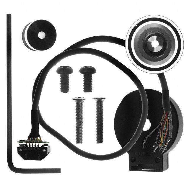
Bourns Inc. 的 ENA1J-B28-L00064L 是一款编码器产品,具体应用场景如下:

 1. 工业自动化
   - 机器人控制:用于检测机器人关节的旋转角度和速度,实现精确的位置控制。
   - 传送带系统:监测传送带的速度和位置,确保物料运输的准确性和稳定性。
   - 数控机床(CNC):提供高精度的角度反馈,用于刀具和工作台的定位。

 2. 汽车领域
   - 电动助力转向系统(EPS):监测方向盘的旋转角度和速度,以调整助力大小。
   - 变速器控制:检测齿轮位置和转速,优化换挡过程。
   - 电动车窗和座椅调节:提供电机旋转角度的反馈,确保操作平滑且安全。

 3. 消费电子
   - 家用电器:如洗衣机、干衣机等设备中,用于监测电机转速和位置,确保洗涤程序的精准运行。
   - 无人机:提供飞行姿态和螺旋桨转速的反馈,增强飞行稳定性。

 4. 医疗设备
   - 医疗影像设备:如CT扫描仪或超声波设备中,用于精确控制机械部件的运动。
   - 康复机器人:监测患者运动数据,辅助康复训练。

 5. 航空航天
   - 飞行控制系统:用于检测舵面或旋翼的角度变化,确保飞行器的稳定性和安全性。
   - 天线定位系统:实现高精度的方向调整。

 特点与优势
- 高分辨率:提供精确的角度测量,适用于对精度要求较高的场景。
- 耐用性:适合在恶劣环境下使用,如高温、振动或潮湿环境。
- 紧凑设计:易于集成到各种设备中,节省空间。

总结来说,ENA1J-B28-L00064L 编码器广泛应用于需要精确角度和速度反馈的场景,覆盖工业、汽车、消费电子、医疗和航空航天等多个领域。
| 参数 | 数值 |
| 产品目录 | |
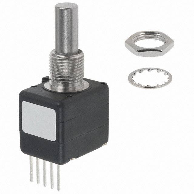
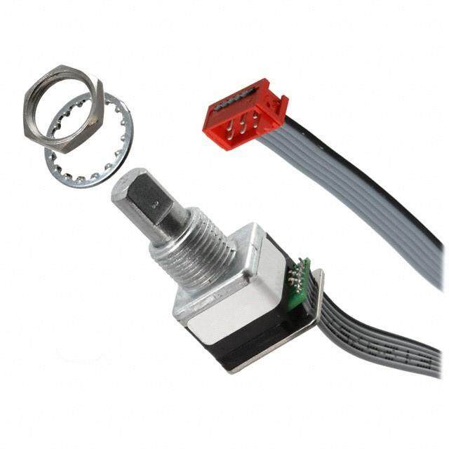
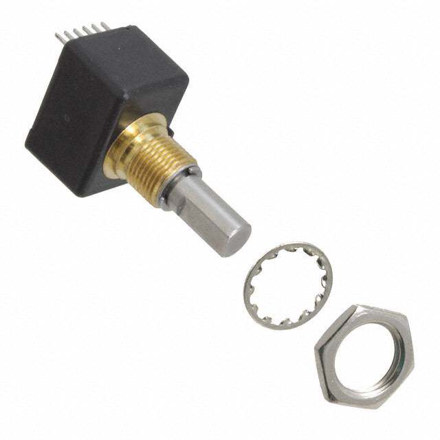
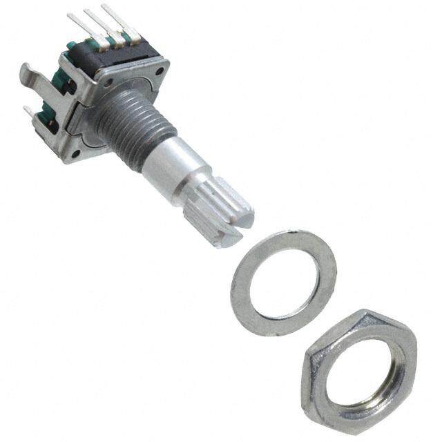
| 描述 | ENCODER OPTICAL ROTARY 64 CPR编码器 1/4" Plain End Axial |
| 产品分类 | |
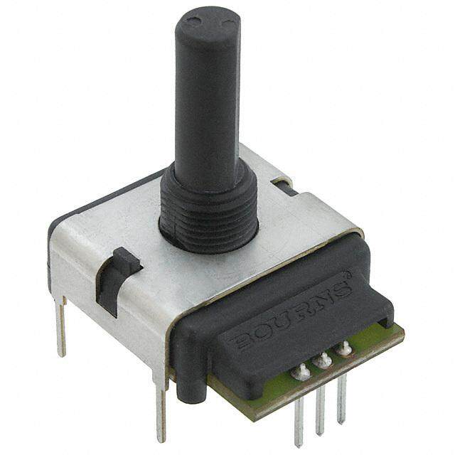
| 品牌 | Bourns |
| 产品手册 | |
| 产品图片 |
|
| rohs | 符合RoHS无铅 / 符合限制有害物质指令(RoHS)规范要求 |
| 产品系列 | Bourns ENA1J-B28-L00064LEN |
| mouser_ship_limit | 该产品可能需要其他文件才能进口到中国。 |
| 数据手册 | |
| 产品型号 | ENA1J-B28-L00064L |
| PCN设计/规格 | |
| 产品 | Optical Encoders |
| 产品目录绘图 |
|
| 产品目录页面 | |
| 产品种类 | |
| 其它名称 | ENA1JB28L00064L |
| 内置开关 | 无 |
| 分辨率 | 64 PPR |
| 商标 | Bourns |
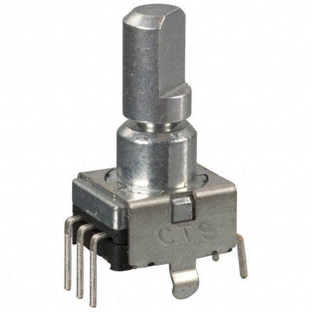
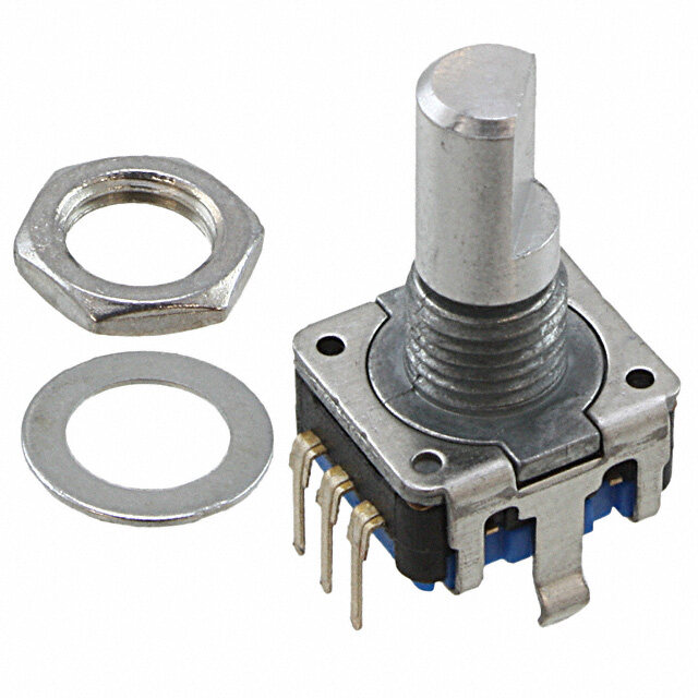
| 安装类型 | 面板,PCB 通孔 |
| 封装 | Bulk |
| 工作温度范围 | - 40 C to + 75 C |
| 工厂包装数量 | 42 |
| 带开关 | Switch |
| 技术 | Rotary |
| 旋转寿命(最少次数) | 10M |
| 朝向 | 垂直 |
| 标准包装 | 1 |
| 棘爪 | 无 |
| 每转脉冲数 | 64 |
| 电压-电源 | 5V |
| 电源电压 | 5 V |
| 端子类型 | PC 引脚 |
| 端接类型 | Through Hole |
| 系列 | EN |
| 编码器类型 | 光学 |
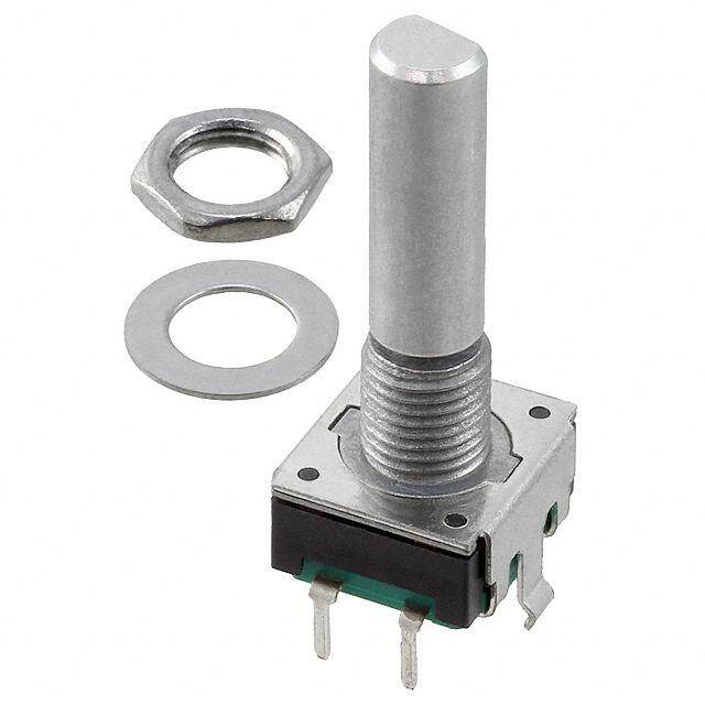
| 致动器类型 | 1/4" 直径圆形端头 |
| 轴直径 | 1/4 in |
| 轴类型 | Round / Plain |
| 输出 | Quadrature |
| 输出类型 | 正交(增量) |
| 通道数量 | 2 Channel |


- 商务部:美国ITC正式对集成电路等产品启动337调查
- 曝三星4nm工艺存在良率问题 高通将骁龙8 Gen1或转产台积电
- 太阳诱电将投资9.5亿元在常州建新厂生产MLCC 预计2023年完工
- 英特尔发布欧洲新工厂建设计划 深化IDM 2.0 战略
- 台积电先进制程称霸业界 有大客户加持明年业绩稳了
- 达到5530亿美元!SIA预计今年全球半导体销售额将创下新高
- 英特尔拟将自动驾驶子公司Mobileye上市 估值或超500亿美元
- 三星加码芯片和SET,合并消费电子和移动部门,撤换高东真等 CEO
- 三星电子宣布重大人事变动 还合并消费电子和移动部门
- 海关总署:前11个月进口集成电路产品价值2.52万亿元 增长14.8%


PDF Datasheet 数据手册内容提取
NT *RoHS VCEOARVMSIAPILOLINAASB LE Features NT MPLIA n Two channel quadrature output n Ball bearing option for high operating O HS C n Bushing or servo mount speed up to 3000 rpm *Ro n Square wave signal n RoHS compliant* n Small size n Resolution to 256 PPR REE n CMOS and TTL compatible D F n Long life LEA EN - Rotary Optical Encoder Electrical Characteristics ORIESnlueusepstucpopltaurlluiyttci . toa.Vi.onl.o .n T.lR..tr..aa..e..gv..s..eei..s...l...t ....a........n........c........e........ ....(....5........0........0........ ....V........D............C........)........ .........................................................................................................L.....V.....EE.....A.....RD.....H S.....ISF..... O.....RC.....NEO.....SE..... M.....AP.....R.....LI..E... .....A.....N.....T.....*.........2........-....b........i....t.... ....q........u........a........d........r....a........t....u........r........e........ ....c....o........d........e........,.... ....C............h........a........n........n........e........l.... ....A........ ....l....e........a........d........s.... ....C............h........a........n........n........e........l.... ....B........ ....b........y........ ....9........0........ ....º.... ....(........e........le...2...c...5...t... r...ti...oc...... a...2...l...)5... ...w6...... ...ict..5h..y... ..c0c..l.. le.Vo1.s.c,D. 0.kp.C0.we.0 Cri±s mro0een. e2vrtogoi5ntol auuVhttoDiimoouCnnss Supply Current....................................................R.o.........................................................................................................................................26 mA maximum Output Voltage Low Output .................................................................................................................................................................................................0.8 V maximum High Output.....................................................................................................................................................................................................4 V minimum Output Current Low Output ................................................................................................................................................................................................25 mA minimum Rise/Fall Time ..................................................................................................................................................................................................200 ns (typical) Shaft RPM (Ball Bearing) .......................................................................................................................................................................3,000 rpm maximum Power Consumption ..................................................................................................................................................................................136 mW maximum Pulse Width (Electrical Degrees, Each Channel) ............................................................................................................................................180 º ±45 º typ. Pulse Width (Index Channel) .................................................................................................................................................................................360 º ±90 º Phase (Electrical Degrees, Channel A to Channel B)........................................................................................................................................90 º ±45 º typ. Environmental Characteristics Operating Temperature Range .......................................................................................................................................-40 ºC to +75 ºC (-40 °F to +167 °F) Storage Temperature Range ..........................................................................................................................................-40 °C to +85 °C (-40 °F to +185 °F) Humidity.................................................................................................................................................................MIL-STD-202, Method 103B, Condition B Vibration ............................................................................................................................................................................................................................5 G Shock...............................................................................................................................................................................................................................50 G Rotational Life A & C Bushings (300 rpm maximum)** ............................................................................................................................................10,000,000 revolutions W, S & T Bushings (3,000 rpm maximum)** ..................................................................................................................................200,000,000 revolutions IP Rating ..........................................................................................................................................................................................................................IP 40 Mechanical Characteristics Mechanical Angle ........................................................................................................................................................................................360 ° Continuous Torque (Starting and Running) A & C Bushings (Spring Loaded for Optimum Feel) ..............................................................................................................1 N-cm (1.5 oz-in.) maximum W, S & T Bushings (Ball Bearing Shaft Support) ..............................................................................................................0.07 N-cm (0.1 oz-in.) maximum Mounting Torque ....................................................................................................................................................1.7 to 2.0 N-m (15 to 18 lb.-in.) maximum Shaft End Play ..................................................................................................................................................................0.30 mm (0.012 ”) T.I.R. maximum Shaft Radial Play ..............................................................................................................................................................0.12 mm (0.005 ”) T.I.R. maximum Weight ..........................................................................................................................................................................................................11 gms. (0.4 oz.) Terminals ......................................................................................................................................................................Axial or radial pc pins or ribbon cable Soldering Condition Manual Soldering ...................................................................................................................96.5Sn/3.0Ag/0.5Cu solid wire or no-clean rosin cored wire 370 °C (700 °F) max. for 3 seconds Wave Soldering ...........................................................................................................................................96.5Sn/3.0Ag/0.5Cu solder with no-clean flux 260 °C (500 °F) max. for 5 seconds Wash processes ....................................................................................................................................................................................Not recommended Marking .................................................................................................................................Manufacturer’s trademark, name, part number, and date code. Hardware .................................................................One lockwasher and one mounting nut supplied with each encoder, except on servo mount versions. **For resolutions ≤ 128 quadrature cycles per shaft revolution. Quadrature Output Table OUTPUT VOLTAGE STANDARD RESOLUTIONS AVAILABLE Channel A (Full quadrature output cycles per shaft revolution) 25* 125 Channel B 50* 128 64 200 100 256 1 cycle 360 ° ± 90 ° For Non-Standard Resolutions—Consult Factory Clockwise rotation * Channel B leads Channel A *RoHS Directive 2002/95/EC Jan. 27, 2003 including annex and RoHS Recast 2011/65/EU June 8, 2011. Specifications are subject to change without notice. The device characteristics and parameters in this data sheet can and do vary in different applications and actual device performance may vary over time. Users should verify actual device performance in their specific applications.
EN - Rotary Optical Encoder Dimensional Drawings (2.1.5040)TYP. (..603255)SRQa.Odpiatli oLneaalds (1.87.35) (6.2.3550) (1.56.2858) Ci•n ocWnlusdiurienlt glfea:acdto oryr cfoarb olep toiopntiso nnsot shown, 2.36 • Connectors (.093) 21.21 • Non-standard resolutions 9.525 (.835) (.375) 1/4-32 UNEF • Special shaft/bushing sizes and 8.636 9.53 features (.34 ) 3.167 + .000/ – .0076DIA. 1.37 (.375) • Special performance characteristics (.1247 + .000/ – .0003) (.054) • PCB mounting bracket Bushing Style C 7.14 + .000/ – .0508 (6.2.344927 ++ ..000000//3 ––/8 ..-00300270 U63)NDEIFA. (1.04.036(29.23 .+ 57+ 35. 0.)00000// – – . 0.050028)DIA. (.28(19.3 .+57 35.0)00/ – .002) DIA. R.(.2.05140 ± . 0.00736) F (.62.43(95.427.51)48) LSE1HN2AG.F7TTH SHL(ADEF2INTM.G5 F.4T LFHA)T (.050) (.100) 15.9 5.08 (.625) (.200) 9.53 1.57 3/8-32 UNEF 1.57 1/4-32 UNEF 19.1 8.25 (.375) (.062) (.062) .787 ± .254 (.750) (.325) 6.342 + .000/ – .0076DIA. 3.167 + .000/ – .0076DIA. (.031 ± .010) 22.2 9.65 (.2497 + .000/ – .0003) (.1247 + .000/ – .003) (.875) (.380) Bushing Style A Bushing Style S Bushing Style T Shaft End Style C (Ball Bearing) (Ball Bearing) 1.57 2.54 4 PLCS. TERMINATION DIAGRAM 1.57 (.062) 11.13 (.100) (.062) 1.57 (.438) 4.14 21.8 (.062) 3.167 + .000/ – .0076 (.163) CHANNEL A CHANNEL B (.86) (.1247 + .000/ – .003)DIA. GROUND N.C. Vcc 18.11 Optional (.713) Radial Leads 0.99 - A + B 9 PLCS.(.039)DIA. MIN. (1.795.0050 ±± ..00102075)DIA. 2 PLCS.(6.2.9795) 22.2 + .0127 / – .1270 DIA. (.875 + .0005 / – .0050) Recommended Board Layout Servo Mount Style W (Ball Bearing) with Bracket Ribbon Cable Option Detail Bushing with Bracket Radial Leads Connector Connector Pinout Pinout 5 5 4 4 —A+B 3 3 2 2 1 1 Axial Ribbon Cable Option Radial Ribbon Cable Option MM DIMENSIONS: (INCHES) Specifications are subject to change without notice. The device characteristics and parameters in this data sheet can and do vary in different applications and actual device performance may vary over time. Users should verify actual device performance in their specific applications.
GENERAL INFORMATION The Bourns® EN model is a self-contained rotary optical encoder. Bourns encoder output signals are square wave digital pulses which It produces a 2-bit quadrature signal which is suitable for digital do not require debounce circuitry. Both features make it possible systems where both magnitude and direction of adjustment must to significantly reduce the memory overhead, wiring and wiring inter- be provided. The EN encoder is ideal for use as a digital panel connects required by other types of control devices. control or as a position sensing device in applications where long life, reliability, high resolution and precise linearity are critical. EN optical encoders offer a useful rotational life of from 10 million to 200 million shaft revolutions, making them ideal for extended service The EN series encoder converts rotary input into electrical signals applications. The Bourns encoder is also compact and well suited for which can be used by microprocessors without A/D conversion. situations where the available space is limited. EN - Rotary Optical Encoder How To Order BOURNS EN SERIES OPTICAL ENCODER E N C 1 J - D 2 8 - L 0 0 1 2 8 L ANTI-ROTATION SHAFT LENGTH* RoHS IDENTIFIER LUG POSITION Code Description Code Description Code Description 16 1/2 " Long L Compliant D None 20 5/8 " Long J 9:00 Position 24 3/4 " Long RESOLUTION P Rear Mount- 28 7/8 " Long Cycles Per ing Bracket Code Revolution TERMINAL*** 00025 ””25 SWITCHING CONFIGURATION 00050 ””50 CONFIGURATION Code Description 00064 ””64 Code Description L Axial, Multi- 00100 100 Channel A Purpose Pin 00125 125 Leads R Radial, Multi- 00128 128 1 Channel B Purpose Pin 00200 200**** By 90 ϒ M Axial, Ribbon 00256 256**** (Clockwise & Connector Rotation)** 10 “ N Radial, Ribbon & Connector 10 ” W Axial, Ribbon 10 “ - No Connector Y Radial, Ribbon 10 ” - No Connector SHAFT STYLE Use With Code Description Bushings (Code) B 1/4 " Dia., Plain End ””A, S D 1/8 " Dia., Plain End C, T, W C 1/4 " Dia., Single A, S Flatted BUSHING CONFIGURATION Code Description A 3/8 "D X 3/8 "L Threaded C 1/4 "D X 1/4 "L Threaded S 3/8 "D X 3/8 "L Threaded (Ball Bearing) T 1/4 "D X 3/8 "L Threaded (Ball Bearing) * Shaft length measured from mounting surface. ** 25 and 50 PPR is reversed (Channel B leads Channel A). W Servo Mount 7/8 "D *** Standard ribbon cable is 10 " long. Consult factory for other lengths. (Ball Bearing) - **** Available with S, T, and W bushing configuration only. Not available with Anti- Rotation Lug option REV. 01/17 Specifications are subject to change without notice. The device characteristics and parameters in this data sheet can and do vary in different applications and actual device performance may vary over time. Users should verify actual device performance in their specific applications.