ICGOO在线商城 > EKK-LM3S3748
 Datasheet下载
- 型号: EKK-LM3S3748
- 制造商: Texas Instruments
- 库位|库存: xxxx|xxxx
- 要求:
| 数量阶梯 | 香港交货 | 国内含税 |
| +xxxx | $xxxx | ¥xxxx |
查看当月历史价格
查看今年历史价格
EKK-LM3S3748产品简介:
ICGOO电子元器件商城为您提供EKK-LM3S3748由Texas Instruments设计生产,在icgoo商城现货销售,并且可以通过原厂、代理商等渠道进行代购。 提供EKK-LM3S3748价格参考¥970.55-¥970.55以及Texas InstrumentsEKK-LM3S3748封装/规格参数等产品信息。 你可以下载EKK-LM3S3748参考资料、Datasheet数据手册功能说明书, 资料中有EKK-LM3S3748详细功能的应用电路图电压和使用方法及教程。
| 参数 | 数值 |
| 产品目录 | 编程器,开发系统嵌入式解决方案 |
| 描述 | BOARD EVAL USB HOST&DEVICE KEIL开发板和工具包 - ARM USB Host Eval Brd Keil tool |
| 产品分类 | 评估板 - 嵌入式 - MCU, DSP工程工具 |
| 品牌 | Texas Instruments |
| 产品手册 | http://www.ti.com/litv/pdf/spms085g |
| 产品图片 |
|
| rohs | 符合RoHS含铅 / 不符合限制有害物质指令(RoHS)规范要求 |
| 产品系列 | 嵌入式开发工具,嵌入式处理器开发套件,开发板和工具包 - ARM,Texas Instruments EKK-LM3S3748Stellaris® |
| 数据手册 | http://www.ti.com/lit/pdf/spmu055点击此处下载产品Datasheethttp://www.ti.com/lit/pdf/spmu025http://www.ti.com/lit/pdf/spmu003http://www.ti.com/lit/pdf/spmu058 |
| 产品型号 | EKK-LM3S3748 |
| 产品 | Development Kits |
| 产品种类 | 开发板和工具包 - ARM |
| 其它名称 | 726-1184 |
| 内容 | 板,电缆,LCD,配件 |
| 制造商产品页 | http://www.ti.com/general/docs/suppproductinfo.tsp?distId=10&orderablePartNumber=EKK-LM3S3748 |
| 商标 | Texas Instruments |
| 安装类型 | 固定 |
| 封装 | Bulk |
| 工作电源电压 | 4.85 V to 5.25 V |
| 工具用于评估 | LM3S3748 |
| 工厂包装数量 | 1 |
| 平台 | - |
| 接口类型 | USB |
| 操作系统 | - |
| 数据总线宽度 | 32 bit |
| 板类型 | 评估平台 |
| 标准包装 | 1 |
| 核心 | ARM Cortex M3 |
| 核心处理器 | ARM® Cortex™-M3 |
| 相关产品 | /product-detail/zh/LM3S3748-IQC50-A0/296-24906-ND/1835772 |
| 类型 | MCU 32-位 |
| 配套使用产品/相关产品 | LM3S3748 |


- 商务部:美国ITC正式对集成电路等产品启动337调查
- 曝三星4nm工艺存在良率问题 高通将骁龙8 Gen1或转产台积电
- 太阳诱电将投资9.5亿元在常州建新厂生产MLCC 预计2023年完工
- 英特尔发布欧洲新工厂建设计划 深化IDM 2.0 战略
- 台积电先进制程称霸业界 有大客户加持明年业绩稳了
- 达到5530亿美元!SIA预计今年全球半导体销售额将创下新高
- 英特尔拟将自动驾驶子公司Mobileye上市 估值或超500亿美元
- 三星加码芯片和SET,合并消费电子和移动部门,撤换高东真等 CEO
- 三星电子宣布重大人事变动 还合并消费电子和移动部门
- 海关总署:前11个月进口集成电路产品价值2.52万亿元 增长14.8%


PDF Datasheet 数据手册内容提取
Stellaris® LM3S3748 Evaluation Kit User ’s Manual EK-LM3S3748-05 Copyright © 2008–2010 Texas Instruments
Copyright Copyright © 2008–2010 Texas Instruments, Inc. All rights reserved. Stellaris and StellarisWare are registered trademarks of Texas Instruments. ARM and Thumb are registered trademarks, and Cortex is a trademark of ARM Limited. Other names and brands may be claimed as the property of others. Texas Instruments 108 Wild Basin, Suite 350 Austin, TX 78746 http://www.ti.com/stellaris 2 January 6, 2010
Stellaris® LM3S3748 Evaluation Kit Table of Contents Chapter 1: Stellaris® LM3S3748 Evaluation Board.......................................................................................9 Features............................................................................................................................................................10 Block Diagram..................................................................................................................................................10 Kit Contents......................................................................................................................................................11 Evaluation Board Specifications...................................................................................................................12 Microcontroller Features...............................................................................................................................12 Chapter 2: Hardware Description..................................................................................................................15 LM3S3748 Microcontroller Overview................................................................................................................15 Clocking........................................................................................................................................................15 Reset.............................................................................................................................................................15 Power Supplies.............................................................................................................................................15 USB...............................................................................................................................................................16 Debugging........................................................................................................................................................17 Debugging Modes.........................................................................................................................................17 Debug In Considerations..............................................................................................................................17 Debug USB...................................................................................................................................................18 USB to JTAG/SWD.......................................................................................................................................18 Virtual COM Port...........................................................................................................................................18 Serial Wire Out..............................................................................................................................................18 Color LCD.........................................................................................................................................................19 Features........................................................................................................................................................19 Control Interface...........................................................................................................................................19 Backlight.......................................................................................................................................................19 Power............................................................................................................................................................20 Oscilloscope.....................................................................................................................................................20 Voltage Reference........................................................................................................................................20 Differential Inputs..........................................................................................................................................20 Test Signals..................................................................................................................................................21 Optimizing the Oscilloscope..........................................................................................................................21 Other Peripherals..............................................................................................................................................22 Speaker.........................................................................................................................................................22 Navigation Switch.........................................................................................................................................23 Status LED....................................................................................................................................................23 Interfacing to the EVB.......................................................................................................................................23 Bypassing Peripherals......................................................................................................................................23 In-Circuit Debugger Interface............................................................................................................................23 Appendix A: Schematics................................................................................................................................25 Appendix B: PCB............................................................................................................................................31 Component Locations.......................................................................................................................................31 Evaluation Board Dimensions...........................................................................................................................33 Appendix C: Bill of Materials (BOM).............................................................................................................35 Appendix D: Connection Details...................................................................................................................39 I/O Breakout Pads............................................................................................................................................39 January 6, 2010 3
DC Power Jack.................................................................................................................................................40 ARM Target Pinout...........................................................................................................................................40 Oscilloscope Header Pinout.............................................................................................................................40 Appendix E: References................................................................................................................................43 4 January 6, 2010
Stellaris® LM3S3748 Evaluation Kit List of Figures Figure1-1. LM3S3748 Evaluation Board...........................................................................................................9 Figure1-2. LM3S3748 EVB Block Diagram....................................................................................................11 Figure2-1. Oscilloscope Acceptable Measurement Range.............................................................................21 Figure2-2. Oscilloscope Connections.............................................................................................................21 Figure2-3. ICD Interface Mode.......................................................................................................................24 FigureB-1. LM3S3748 Evaluation Board Component Locations.....................................................................32 FigureB-2. LM3S3748 Evaluation Board Dimensions.....................................................................................33 FigureD-1. DC Power Jack..............................................................................................................................40 January 6, 2010 5
6 January 6, 2010
Stellaris® LM3S3748 Evaluation Kit List of Tables Table2-1. Board Power Options....................................................................................................................16 Table2-2. USB-Related Signals.....................................................................................................................16 Table2-3. LM3S3748 EVB Hardware Debugging Configurations..................................................................17 Table2-4. Debug-Related Signals.................................................................................................................18 Table2-5. LCD-Related Signals.....................................................................................................................19 Table2-6. Oscilloscope Electrical Specifications...........................................................................................20 Table2-7. Speaker-Related Signals...............................................................................................................22 Table2-8. Navigation Switch-Related Signals...............................................................................................23 TableC-1. LM3S3748 Bill of Materials............................................................................................................35 TableD-1. I/O Breakout Pads.........................................................................................................................39 TableD-2. ARM Target Pinout........................................................................................................................40 TableD-3. Oscilloscope Header Pinout..........................................................................................................40 January 6, 2010 7
8 January 6, 2010
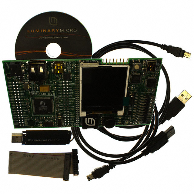
C H A P T E R 1 Stellaris® LM3S3748 Evaluation Board The Stellaris® LM3S3748 Evaluation Board (EVB) is a compact and versatile evaluation platform for the Stellaris LM3S3748 ARM® Cortex™-M3-based microcontroller. The evaluation board design highlights the LM3S3748 microcontroller's key features including USB 2.0 full-speed (12Mbps) controller, Analog-to-Digital Converter (ADC), and serial interfaces. The LM3S3748 EVB has connectors for both embedded USB Host and USB Device operation; allowing a range of USB application options to be evaluated. In USB Device mode, a small switch selects between bus-powered and self-powered options. Four ADC signals are paired as two differential channels to implement a 1MS/s oscilloscope application on the LCD panel. The oscilloscope feature set includes USB host and device connectivity as well as SD card support. The LM3S3748 EVB may be used either as an evaluation platform or as a low-cost in-circuit debug interface (ICDI). In Debug Interface mode, the on-board microcontroller is bypassed, allowing programming or debugging of an external target. The LM3S3748 Evaluation Kit enables rapid evaluation and prototyping of LM3S3748 microcontroller designs. The kit also includes extensive example applications and complete source code. Figure1-1 shows the LM3S3748 EVB in detail. Figure1-1. LM3S3748 Evaluation Board Color LCD Panel MicroSD card slot USB Device Connector Oscilloscope terminals USB Host Connector Reset switch USB interface 5 VDC supply for Debugger input USB Power Mode Switch Stellaris LM3S3748 JTAG/SWD Microcontroller input and output 34-pin I/O break-out header Status LED 34-pin I/O break- out header Speaker Navigation switch with press-to-select January 6, 2010 9
Features Features The Stellaris LM3S3748 Evaluation Board includes the following features: (cid:132) Stellaris LM3S3748 microcontroller (cid:132) 2-channel oscilloscope demo application (cid:132) USB Host and Device connectors (cid:132) Bus-powered or self-powered (cid:132) Simple setup; USB cable provides serial communication, debugging, and power (cid:132) Color LCD graphics display with 128x128 pixel resolution (cid:132) User LED, and navigation switch with press to select (cid:132) 8Ω Magnetic speaker with amplifier (cid:132) microSD card slot (cid:132) USB interface for debugging and power supply (cid:132) DC jack for optional 5V power supply (cid:132) Standard ARM® 20-pin JTAG debug connector with input and output modes (cid:132) LM3S3748 microcontroller I/O available on labeled break-out pads Block Diagram Figure1-2 on page 11 shows the LM3S3748 EVB block diagram. 10 January 6, 2010
Stellaris® LM3S3748 Evaluation Kit Figure1-2. LM3S3748 EVB Block Diagram ete gbl TarCa I/OSignalBreak-out I/OSignalBreak-out JTAG/SWD g u Output/Input b e D LCDDisplay CSTN128x128 x Dual Mu Debug DeUbSugBUSB DUeSviBce TAG nals J g Controller D/ si W UART0 O S I/ LED USB Stellaris DevUicSeBMode Mini-B h DustDevil connector witc Microcontroller Switch S USB Nav B USB S Switch U HoUsStBMode TypeA ‘Scope connector CH1 Input 1.5V +5Vhostsupply Control reference ‘Scope CH2 Input +3.3V Regulator Reset USB Host/DeviceEvaluationBoard Kit Contents The Stellaris LM3S3748 Evaluation Kit contains everything needed to develop and run USB applications using Stellaris microcontrollers including: (cid:132) LM3S3748 Evaluation Board (EVB) (cid:132) USB cables (1 each for device and debugger use) (cid:132) USB flash memory stick (cid:132) Four oscilloscope test leads (cid:132) 20-pin JTAG/SWD target cable (cid:132) CD containing: – A supported version of one of the following (including a toolchain-specific Quickstart guide): • Keil™ RealView® Microcontroller Development Kit (MDK-ARM) • IAR Embedded Workbench January 6, 2010 11
Kit Contents • Code Sourcery GCC development tools • Code Red Technologies development tools • Texas Instruments’ Code Composer Studio™ IDE – Complete documentation – Quickstart application source code – Stellaris® Firmware Development Package with example source code Evaluation Board Specifications (cid:132) Board supply voltage: 4.85–5.25Vdc from one of the following sources: – Debugger USB cable (connected to a PC) – Device USB cable (connected to a PC) – DC power jack (cid:132) Board supply current: 130mA typ (fully active, CPU at 50MHz, no audio) (cid:132) Break-out power output: 3.3Vdc (100mA max) (cid:132) Speaker power: 0.3W max (cid:132) Dimensions: 4.65”x2.45”x0.33” (LxWxH) (cid:132) RoHS status: Compliant When the EVB is used in USB Host mode, the host connector is capable of supplying power to the connected USB device. The available supply current is limited to ~250mA unless the EVB is powered from an external 5V supply with a ≥600mA rating. Microcontroller Features The LM3S3748 microcontroller includes the following product features: (cid:132) 32-bit RISC performance using ARM® Cortex™-M3 v7M architecture – 50-MHz operation – Hardware-division and single-cycle-multiplication – Integrated Nested Vectored Interrupt Controller (NVIC) – 37 interrupt channels with eight priority levels (cid:132) 128KB single-cycle flash (cid:132) 64KB single-cycle SRAM (cid:132) Pre-programmed ROM (cid:132) DMA controller (cid:132) Two SSI modules (cid:132) One USB Host controller (cid:132) Four general-purpose 32-bit timers (cid:132) Two fully programmable 16C550-type UARTs (cid:132) Eight 10-bit ADC channels (inputs) when used as single-ended inputs 12 January 6, 2010
Stellaris® LM3S3748 Evaluation Kit (cid:132) Two integrated analog comparators (cid:132) Two I2C modules (cid:132) Four PWM generator blocks (cid:132) One QEI module with position integrator for tracking encoder position (cid:132) 3 to 61 GPIOs, depending on user configuration (cid:132) On-chip low drop-out (LDO) voltage regulator (cid:132) Hibernation module January 6, 2010 13
Kit Contents 14 January 6, 2010
C H A P T E R 2 Hardware Description In addition to a microcontroller, the Stellaris® LM3S3748 evaluation board includes a range of useful peripheral features and an integrated in-circuit debug interface (ICDI). This chapter describes how these peripherals operate and interface to the microcontroller. LM3S3748 Microcontroller Overview The heart of the EVB is a Stellaris LM3S3748 ARM® Cortex™-M3-based microcontroller. The LM3S3748 microcontroller offers 128-KB flash memory, 64-KB SRAM memory, 50-MHz operation, USB, and a wide range of peripherals. See the LM3S3748 microcontroller data sheet (order number DS-LM3S3748) for complete device details. The LM3S3748 microcontroller is factory-programmed with a quickstart demo program. The quickstart program resides in on-chip flash memory and runs each time power is applied, unless the quickstart has been replaced with a user program. Clocking The EVB uses an 8.0-MHz crystal to complete the LM3S3748 microcontroller's main internal clock circuit. An internal PLL, configured in software, multiplies this clock to 50MHz for core and peripheral timing. The real-time clock oscillator is part of the microcontroller's Hibernation module and uses a 4.194304MHz crystal for timing. This frequency divides by 128 to generate a 32.7680kHz standard timing frequency. Reset The LM3S3748 microcontroller shares its external reset input with the LCD display. In the EVB, reset sources are gated through the CPLD, though in a typical application, a simple wired-OR arrangement, with a resistor to +3.3V, is sufficient. External reset is asserted (active low) under any one of these conditions: (cid:132) Power-on reset (cid:132) Reset push switch SW1 held down (cid:132) By the USB device controller (U5 FT2232) when instructed by the debugger Power Supplies The EVB has two main power rails. A +3.3V supply powers the microcontroller and most other circuitry. A +5V supply is used by the Host USB port and In-circuit Debug Interface (ICDI) USB controller. A low drop-out (LDO) regulator (U8) converts the +5V power rail to +3.3V. Both rails are routed to pads on the I/O break-out headers and may be used to power external circuits. January 6, 2010 15
LM3S3748 Microcontroller Overview EVB power can be supplied through three different connectors as shown in Table2-1. Table2-1. Board Power Options Main Features USB Host Feature Power Source Reference Powered? Powered DC Jack J5 Yes Yes USB Device connector J6 Yesa No Debug Interface USB J7 Yes Yes connector a. To power the EVB, the USB power switch (SW3) must be in the “BUS” position. Only one power source should be connected to the EVB. If the USB Power switch (SW3) is in the BUS position, the board should be powered from J6 (USB Device connector). If the USB Power switch is in the SELF position, the board should be powered from J7 (Debug USB connector) or from J5 (DC power jack). Do not apply power to J5 and J7 at the same time. The current and voltage available on the USB host port is a function of the EVB power source. If board power is provided by a USB cable, the host port power is limited to 500mA minus the EVB power requirements. Use the DC jack to provide power from a +5V source if a full 500mA USB host supply is necessary on J7. USB The LM3S3748's full-speed USB controller supports both Host and Device configurations. In Host mode, the EVB acts as a host for USB devices connected to J1. In Device mode, the EVB acts as a device and can be connected to another USB host, such as a PC. The EVB has dedicated USB Host and USB Device connectors. A multiplexer (U9), controlled by a GPIO pin (PH2/PB0), determines which port is active by switching D+ and D- signals. Each port has additional ESD protection diode arrays (D9, D10) for up to 15kV of electrostatic discharge (ESD) protection. Table2-2. USB-Related Signals Microcontroller Pin EVB Function To isolate, remove... Pin 70 USBDM USB Data- - Pin 71 USBDP USB Data+ - Pin 73 USBRBIAS USB bias resistor - Pin 66 PB0 Input (see Rev A0 errata) - Pin 67 PB1 Input (see Rev A0 errata) - Pin 84 PH2 USB Host/Device mux control JP33 Pin 83 PH3/USB0EPEN Host power enable (active high) - Pin 76 PH4/USB0PFLT Host power fault (active low) - U7, a fault-protected switch, controls and monitors power to the USB Host port. USB0EPEN, the control signal from the microcontroller, has a pull-down resistor to ensure Host-port power remains 16 January 6, 2010
Stellaris® LM3S3748 Evaluation Kit off during reset. The power switch immediately cuts power if the attached USB device draws more than 1Amp, or if the switches' thermal limits are exceeded by a device drawing more than 500mA. Under fault conditions, U7 will set its over-current output pin low. This is an open-drain signal, so a pull-up must be enabled by the microcontroller. The USB controller can be configured to generate an interrupt if USB0PFLT is asserted. The EVB can be either a bus-powered USB device or self-powered USB device depending on the position of the USB power switch (SW3). WARNING – Do not change the USB power selection while power is applied. Doing so may damage the switch contacts. When using the EVB in USB-Host mode, power to the EVB should be supplied by the In-circuit Debugger (ICDI) USB cable or by a +5V source connected to the DC power jack. Set the USB power switch to self-power. Note that the LM3S3748 microcontroller’s USB capabilities are completely independent from the ICDI USB functionality. Debugging Stellaris microcontrollers support programming and debugging using either JTAG or SWD. JTAG uses the signals TCK, TMS, TDI, and TDO. SWD requires fewer signals (SWCLK, SWDIO, and, optionally, SWO for trace). The debugger determines which debug protocol is used. Debugging Modes The LM3S3748 EVB supports a range of hardware debugging configurations. Table2-3 summarizes these configurations. Table2-3. LM3S3748 EVB Hardware Debugging Configurations Mode Debug Function Use Selected by... 1 Internal ICDI Debug on-board LM3S3748 Default mode microcontroller over Debug USB interface. 2 ICDI out to JTAG/ The EVB is used as a USB to Connecting to an external target and SWD header SWD/ JTAG interface to an starting debug software. external target. The red Debug Out LED will be ON 3 In from JTAG/SWD For users who prefer an external Connecting an external debugger to header debug interface (ULINK, JLINK, the JTAG/SWD header etc.) with the EVB. Modes 2 and 3 automatically detect the presence of an external debug cable. When the debugger software connected to the EVB's USB controller the EVB automatically selects Mode 2 and illuminates the red Debug Out LED. Debug In Considerations Debug Mode 3 supports evaluation board debugging using an external debug interface. Mode 3 is automatically selected when a device such as a Segger J-Link or Keil ULINK is connected to the EVB. January 6, 2010 17
Debugging Debug USB An FT2232 device from Future Technology Devices International Ltd manages USB-to-serial conversion. The FT2232 is factory-configured to implement a JTAG/SWD port (synchronous serial) on channel A and a Virtual COM Port (VCP) on channel B. This feature allows two simultaneous communications links between the host computer and the target device using a single USB cable. Separate Windows drivers for each function are provided on the Documentation and Software CD. The ICDI USB capabilities are completely independent from the LM3S3748's on-chip USB functionality. A small serial EEPROM holds the FT2232 configuration data. The EEPROM is not accessible by the LM3S3748 microcontroller. For full details on FT2232 operation, go to www.ftdichip.com. USB to JTAG/SWD The FT2232 USB device performs JTAG/SWD serial operations under the control of the debugger. A CPLD (U6) multiplexes SWD and JTAG functions and, when working in SWD mode, provides direction control for the bidirectional data line. The CPLD also implements logic to select between the three debug modes. The target microcontroller selection is determined by multiplexing TCK/SWCLK. Virtual COM Port The Virtual COM Port (VCP) allows Windows applications (such as HyperTerminal) to communicate with UART0 on the LM3S3748 over USB. Once the FT2232 VCP driver is installed, Windows assigns a COM port number to the VCP channel. Table2-4. Debug-Related Signals Microcontroller Pin EVB Function To isolate, remove... Pin 77 TDO/SWO JTAG data out or trace data out - Pin 78 TDI JTAG data in - Pin 79 TMS/SWDIO JTAG TMS or SWD data in/out - Pin 80 TCK/SWCLK JTAG Clock or SWD clock - Pin 26 PA0/U0RX Virtual Com port data to LM3S3748 JP12 Pin 27 PA1/U0TX Virtual Com port data from LM3S3748 JP25 Serial Wire Out The EVB supports the Cortex-M3 Serial-Wire Output (SWO) trace capabilities. Under debugger control, the CPLD can route the SWO datastream to the VCP transmit channel. The debugger can then decode and interpret the trace information received from the Virtual Com Port (VCP). The normal VCP connection to UART0 is interrupted when using SWO. Not all debuggers support SWO. Refer to the Stellaris LM3S3748 Datasheet for additional information on the Trace Port Interface Unit (TPIU). 18 January 6, 2010
Stellaris® LM3S3748 Evaluation Kit Color LCD The EVB features a liquid crystal graphics display with 128x128 pixel resolution. The display is protected during shipping by a thin, protective plastic film. Remove the film by gently pulling the green tab. Features The color LCD includes the following features: (cid:132) Formike Electronic KWH015C04-F01 display (cid:132) CSTN 128x‘ h128 resolution (cid:132) 16-bit color (cid:132) White LED backlight (cid:132) 8-bit data bus (cid:132) ST7637 Drive IC Control Interface The color LCD module has a built-in controller IC with an 8-bit parallel interface. Port G is used to transfer data to and from the LCD module. Three control signals (A0, WR, RD) provide read/write and register/data control using GPIO pins. Table2-5. LCD-Related Signals Microcontroller Pin EVB Function To isolate, remove... Pin 19 PG0 LCD Data 0 JP16 Pin 18 PG1 LCD Data 1 JP14 Pin 19 PG2 LCD Data 2 JP17 Pin 16 PG3 LCD Data 3 JP18 Pin 41 PG4 LCD Data 4 JP26 Pin 40 PG5 LCD Data 5 JP27 Pin 37 PG6 LCD Data 6 JP28 Pin 36 PG7 LCD Data 7 JP29 Pin 25 PC4 LCD Write Enable (active low) JP30 Pin 24 PC5 LCD Read Enable (active low) JP21 Pin 72 PB2 LCD Register / Data select JP11 Pin 61 PF1/PWM1 Backlight control JP19 Backlight The white LED backlight must be powered for the display to be visible. Set PF1/PWM1 high to turn on the backlight. For brightness control, use the pin's PWM function to reduce the normal 34mA supply current. January 6, 2010 19
Oscilloscope Power The LCD module has internal bias voltage generators and requires only a single 3Vdc supply, which is provided via D2 and D3. Oscilloscope The oscilloscope feature has two differential measurement channels which provide waveform acquisition using the LM3S3748 microcontroller's Analog-to-Digital Converter (ADC). This section describes the oscilloscope hardware. For a detailed description of the oscilloscope operation and software, see the Stellaris® Peripheral Driver Library User's Guide in the LM3S3748 Evaluation Kit’s Example Applications section. Voltage Reference The oscilloscope circuit can measure negative voltages by biasing the oscilloscope input channels to +1.5V. A voltage divider is buffered by an op-amp (U2) for a low impedance voltage reference. The reference voltage varies proportionally with the 3.3 V rail, but the differential measurement configuration will successfully reject this error. Differential Inputs Both input channels have 11:1 differential input voltage dividers. For accuracy, 0.1% resistors are used. The ADC inputs to the LM3S3748 microcontroller have two key parameters sets in this application circuit. The first are the common-mode (absolute) voltage limits of 0 to 3.0V. This sets the voltage limit on any oscilloscope input signal to +16.5V to -16.5V, using the following equations: Vcm = (Vadc - Vref) * 11 = +16.5V (max+) (max) Vcm = (Vadc - Vref) * 11 = -16.5V (max-) (min) The second key parameter set is the differential mode voltages limits, which are +1.5V and -1.5V. These values are important in defining the maximum voltage between the inputs to each channel. Vdm = Vadc * 11 = +/-16.5V (diff) Table2-6. Oscilloscope Electrical Specifications Parameter Name Min Nom Max Units Common Mode Input Voltage -16.5 – +16.5 V Differential Input Voltage – – +16.5 V Differential Input Voltage – – -16.5 V Input Impedance – 220K – Ω 20 January 6, 2010
Stellaris® LM3S3748 Evaluation Kit Figure2-1. Oscilloscope Acceptable Measurement Range +16.5V Acceptable 0 measurement range -16.5V Min Max Test Signals The oscilloscope inputs may be used to measure voltages and waveforms at various points on the board. Consider the oscilloscope's input impedance (220KΩ) when selecting signals to measure. The EVB has two defined test points that can be easily accessed on the oscilloscope header. Figure2-2. Oscilloscope Connections Test Ground Test Point 2 Channel 1- Channel 2+ Channel 1+ Channel 2- Test Point 1 Test Ground The oscilloscope test leads, included in the evaluation kit, have pin-sockets that are compatible with a wide range of test probes, clips, and hooks that have 0.025" square terminal posts. Optimizing the Oscilloscope The oscilloscope hardware is a simple design that balances trade-offs between input impedance, signal bandwidth, and measurement error. January 6, 2010 21
Other Peripherals Measurement error is introduced when an ADC is fed from a high-impedance source. Each time the ADC makes a conversion, a very small capacitor in the ADC input-stage must be charged. During the charging period, the voltage may drop slightly. Using only one oscilloscope channel will reduce the error, because the internal capacitance charges to approximately the same level for each conversion. The error can also be reduced by adding a capacitor across the differential inputs to the ADC (for example, between ADC0 and ADC1). Adding 33pF capacitors will stabilize the input to the ADC, however, it will also create a 24-kHz low-pass filter. This will limit the usable bandwidth of the oscilloscope, but will optimize it for DC level measurements. Another method is to reduce the values of the input divider resistors. The best overall solution would be a high-performance op-amp buffer stage. Other Peripherals Speaker The LM3S3748 evaluation board's speaker circuit can be used in either tone or waveform mode. In tone mode, the LM3S3748 microcontroller's PWM module directly generates tones within the audible frequency range. The width of the pulses determines the volume. If only one PWM signal (PWM2 or PWM3) is used, then the non-PWM signal should be configured as a general-purpose output. For increased speaker volume, PWM2 and PWM3 can be configured as complementary drive signals. In tone and waveform modes, be careful to avoid large DC currents in the speaker. Do not drive the PWM levels to opposite polarities for more than 10 ms. Waveform mode uses two high-frequency PWM signals to drive a MOSFET H-bridge with an output filter. This circuit is essentially a Class-D amplifier. The symmetrical 2nd order low-pass L-C filter has a cut-off frequency of approximately 33kHz. The microcontroller's PWM module should be configured with a PWM frequency of at least 66kHz. Using higher frequencies (for example, 500kHz) improves audio quality. Once configured, audio waveform data can be used to update the PWM duty cycle at a rate equal to the audio sampling rate. The speaker on the evaluation board has standard 8-Ω impedance. Audio quality can be enhanced by adding a small, vented enclosure around the speaker. Table2-7. Speaker-Related Signals Microcontroller Pin EVB Function To isolate, remove... Pin 60 PF2/PWM2 Audio PWM + JP22 Pin 59 PF3/PWM3 Audio PWM - JP20 22 January 6, 2010
Stellaris® LM3S3748 Evaluation Kit Navigation Switch The EVB has a four-way navigation switch (SW2) with press-to-select functionality. Each of the five signals connects to GPIO pins on the LM3S3748 microcontroller. The internal 200kΩ pull-up resistors should be enabled before reading switch status. Table2-8. Navigation Switch-Related Signals Microcontroller Pin EVB Function To isolate, remove... Pin 65 PB3 Up Switch JP13 Pin 92 PB4 Down Switch JP10 Pin 91 PB5 Left Switch JP9 Pin 90 PB6 Right Switch JP23 Pin 89 PB7 Select Switch D1 The press-to-select switch also connects to the WAKE signal on the LM3S3748's microcontroller’s Hibernate module. Diode D1 blocks current from the WAKE internal pull-up when in Hibernate mode. The diode is transparent in normal switch operation. Status LED A user LED (LED3) is provided for general use. The LED is connected to PG2/PWM0, allowing the option of either GPIO or PWM control (brightness control). Interfacing to the EVB An array of accessible I/O signals makes it easy to interface the EVB to external circuits. All LM3S3748 I/O lines (except those with both JTAG and SWD functions) are brought out to 0.1"pitch pads. For quick reference, silk-screened labels on the PCB show primary pin functions. Table x on page y has a complete list of I/O signals as well as recommended connectors. Most LM3S3748 I/O signals are +5-V tolerant. Refer to the LM3S3748 microcontroller data sheet for detailed electrical specifications. Bypassing Peripherals The EVB's on-board peripheral circuits require 30 GPIO lines. This leaves 23 GPIO lines immediately available for connection to external circuits. If an application requires more GPIO lines, the on-board hardware can be disconnected. The EVB is populated with 30 jumper links, which can be cut with a knife to isolate on-board hardware. The process can be reversed by installing 0603- 0-ohm chip resistors. NOTE: The quickstart application will not run if one or more jumpers are removed. In-Circuit Debugger Interface The LM3S3748 Evaluation Kit can operate as an In-Circuit Debugger Interface (ICDI). ICDI acts as a USB to the JTAG/SWD adaptor, allowing debugging of any external target board that uses a Stellaris microcontroller. See “Debugging” on page17 for a description of how to enter Debug Out mode. January 6, 2010 23
In-Circuit Debugger Interface Figure2-3. ICD Interface Mode Connecting Pin 18 to GND sets JTAG or SWD connects to the external debug mode external microcontroller Evaluation Board Target Stellaris Target Stellaris Cable MCU Board USB MCU ` PC with IDE/ debugger TCK/SWCLK bypasses the on-board microcontroller The debug interface operates in either serial-wire debug (SWD) or full JTAG mode, depending on the configuration in the debugger IDE. The IDE/debugger does not distinguish between the on-EVB Stellaris microcontroller and an external Stellaris microcontroller. The only requirement is that the correct Stellaris device is selected in the project configuration. The Stellaris target board should have a 2x10 0.1" pin header with signals as indicated in TableD-2 on page40. This applies to both an external Stellaris microcontroller target (Debug Output mode) and to external JTAG/SWD debuggers (Debug Input mode). ICDI does not control RST (device reset) or TRST (test reset) signals. Both reset functions are implemented as commands over JTAG/SWD, so these signals are usually not necessary. It is recommended that connections be made to all GND pins; however, both targets and external debug interfaces must connect pin 18 and at least one other GND pin to GND. Some external debug interfaces may require a voltage on pin 1 to set line driver thresholds. The EVB ICDI circuit automatically sets pin 1 high if an external debugger is connected. In other modes, this pin is unused. 24 January 6, 2010
A P P E N D I X A Schematics This section contains the following schematic diagrams for the LM3S3748 evaluation board: (cid:132) Microcontroller on page26 (cid:132) Power, USB Selection on page27 (cid:132) LCD, Switches, and Audio on page28 (cid:132) Debugger Interfaces on page29 (cid:132) JTAG Logic with Auto Mode Detect, Hibernate, and TVcc Control on page30 January 6, 2010 25
Microcontroller 1 2 3 4 5 6 I/O Break-out Headers OfJruemen pG-ebPrsIoO ca alinnr edbse i Lfc ruCet qtDouir eSd.ignals Stellaris LM3S3748 MicroconPHtr2o/FlAleULrT3 PPNHBot02e tc1oo: nHtOroSlsT UESn Bco mnnuexc (taionnd rPeBqu0i riendp ufto rp eRre evr rAat0a )s.ilicon. PPBH60//CC0C+P6 34 33 PPBB47//CN0M-I PB5/C1-+VBUS 68 67 PPAHD32B//SFGSA+IU50VFLSTS3 A LLLCCCLLLLLLDDCCCCCCD_DDDDDD__WRA012345D0R JJJJJJJJJPPPPPPPPP211111322614678071 PPPPPBGGPGGPP235GCC///01IFF2//544AAPPC///CCCWWUUP0C1CGSLLMM+PPCTT24543L21 PTCMI3PN/STCT/D2S_/OTWTCD/DSKIWIOO PPPPPPPPPPPPPPAAAAAAAACCCCCC45673212345067//////////////CCUUTTISSUUSSI22SSSSDDC11100CCIIII+RTRTPOI000011XXX4XCRFTSS/SSDCXLXWSKLAO22223387772222336789010987543245 U?PPPPPPPPPPPPPPPPAAAAAACCCCCCCCAA0123456710234567////////////////UTTTCCUTUUSSSSII22SSSSCDDMC11100CCIIII+TRTRKIOP0000S11XXX4XCFRT/SS//SSSSXCDLXWWWSKLACODLIOK PPBB3PPPP2PPPP/DDDD/DIPDDIDP2PP24567B1BC230CBB/////7//AAAA/6P0CC0I45//SDHNDDDDS//CCCPPCCDCXAMCCCCBB0PP01AL+5000176540--I 199919991116786601789052102329670 PPPPPPPPPPPPPPDDDDBBBBBBDDDD65432732104567//////////////CCCIINCCPIAAAA22DH010CCMDDDDCCX+--APP0CCCC00I0 05JSS0O7654PDCh3LAm3 PN0 BJoOUPt1he3HS mj4B2uO:m0SVpTeBErUnedS to+ +55VV per Rev A0 errata. PPPPPPPPPPPPPPADACEEEGGDDDCA25757104272466/////////////SAACUCSAAIUPID2SSWDD1C1DD0CIXI+TT1CCP0CC1M0XRX5RS20757XCXL 21 PPPPPPPPPPPPPEADEECGDCAADD3644653112775/////////////SAACUSSCAAIPP2SSSWHDDCC1DDCIIIRAP1CCP00CC1MTX40CTS130465XDXLKA PPPPPPPPPPCGFHEGFFBB6131223416//////////CPPSITICCPV22WWSCWDCCCCBIPI1MMPP00AM1F37SS13TS6DCSLA 36 35 PPPPPPPPPPPFFFFFGEGGCA45702030530///////////FCPPPSTFFPUAHWWSCAAWD0IUBPRUUO1MMM20CLXLL/02S4TLTTW0K12O+3.3V A JP28 B LLCCDD67 JP29 PPGG67//PPWWMM67 PPPPPPPPEEEEEEEE31024567////////SSSSAAAASSSSDDDDIIII1111CCCCFTCR3210SXLXSK 779945566521 PPPPPPPPEEEEEEEE30124567////////SSSSAAAASSSSDDDDIIII1111CCCCTCRF3210SXLXSK PFPPPP4PPFFFFP/FFF0123FA////567PPPP///UCCWWWWPLCChMMMMBTPP21012300 4665544471098632 PPPPPPPPFFFFFFFF47012356////////CCPPPPPFAHWWWWCCUBPPMMMM210L0123T0 OfJPruEem7es/ pAGceDPirlCsIlO o0c/aAsnDc bCoe lpicnJJueePPts 56t oiSf reigquniraedl.sAINAP POfJruAemen0 /pGU-eb0PrRsIoO Xca alinnre dbse i Pfc JJruePPet q12tr25ouiiprehd.eraVlC SP_iRgXnals B PPPPPPPPGGGGGGGG01234567///////CPPFFPPAAWWWWCUUPMMMM3LL4567TT21 1111443398761076 PPPPPPPPGGGGGGGG01234567///////PPFCFPPAAWWWWCUUPMMMM3LL4567TT21 PH4/NPHMP3IH//UU2PPSS/HHFBBA0100//EUCCPPFLCCELTPPNT673 8888746536 PPPHHH012///CCFACCUPP67LT3 UUSSBB00PEFPLET PPPEEE654///AAADDDCCC123 JJPP87 AAAIIINNNABBMMP PPPAAA132///SSUSS0IIT00XFCSLSK JJJPPP124 CCVAACRRPDD_CCTLXSKn Y1 YR1M12 HIBn D6 WAKEn 445555890123 OOWHXXIOOSSABCCSSK01CCE01 USBUU0SSRVBBBD00DIDDAMAPS 7773130 R9.310K UUSSBBDDMP +3.3V PPPPAFFA1045////PPSSWWSSIIMM00RT10XX JJJPPP31294 BACCCAALKRRELDDDIRTGXXHT C RH0ABevisistioo1Cn01r1P8yF.0JAJDau0apnlM rt 3 3e2H,1 ,20 z,00888 AADFF1Ciieddnr02sddsaPt lc FPp ppruBrriolpo1ld-tt uoutiopotcy t +noipo5nenV42C rr .7ree3 11ejPslu9eleFe4mata 3sspse0wee4riM.tc2hH.z 2C74PF MCURSTnM+A32.3JR1V7022KCO85MIT 1236345566889513495473927494 GGGGRGGGGGGGGGGSNNNNNNNNNNNNNNTDDDDDDDDDDDDDDA VVVVVVVVVVVVVDDDDDDDDDDDDLBDDDDDDDDDDDDDA333333332222OT333333335555 57823456891368502468134828 VBAT C00C..6180U1UFF 0C.901UF C0.111UF C0.113UF C1U15F PPPPPPPWFFBBBBBA2334567//K/////PPICCCN2EWW010MCn--+MM0IS23DA DMJJJJJJJPPPPPPP1A91112220353202J728 SDRELIOSLUSEGOWOEFPHUCTU_NTS_TNN__WS_DSSDWSWWn+-Wnnnn C C10 LM3S3748 C7 C12 C14 C16 1UF 0.01UF 0.1UF 0.1UF 0.1UF D D Drawing Title: Stellaris USB Host/Device Eval Board Page Title: Microcontroller Size B Document Number:BD-LM3S3748 Date: 7/3/2008 Sheet 1 of 4 RevA 1 2 3 4 5 6
Power, USB Selection 1 2 3 4 5 6 Bus-Power / Self-Power Switch A DEVICE+5V 3 SW3 1 +5V UPQ81LA333MSPQ +3.3V A 26 4 VIN VOUT 5 4 5SSSS820201 C1U36F HIBn10R03K8 3 ON GND NR 1 C37 C1U38F J1 U1S54B-U AHRO42-SET 2 0.01UF 5 V D- D+ G 6 +5V DC INPUT +VBUS D4 1 J5 123 MBR0520 Main +3.3V 200mA Power Supply 234 PJ-014D-SMT B B USB DEVICE J6 54819-0572 DBG+5V D9 +3.3V +VBUS TPD2E001DRL 5V D- D+ ID G R44 1 VCC GND 4 6 7 0 Ohm HOSTEn 1103 U9SS12 VVCCCC 1141 C0.410UF C0.412UF 3IO12N.C.5IO2 1 2 3 4 5 +5VIN 2 UTP7INS2051BDGNOUT 6 +VBUS USBDP 1 D+ DD11+- 63 DEVICE+5V OJPm32it C35 USB0EPE 34 IENN D OOUUTT 78 + C15309uF USBDM 4 D- DD22+- 912 1UF USB0PFLT 5 OCn GN 10V C R10309K 1 78 FSNNUCCSB11MTCGGXNNDD 52 DEVICE+5V1 V3CIO1C2N.C.5GIO2ND 4 C C41 D10 VBUS Fault Protected Switch HOSTEn Low = USB Host selected 0.1UFTPD2E001DRL HOSTEn High = USB Device selected Host/Device Selector +3.3V D7 VBAT DEVICE+5V MA2J728 R1.452K RO4m0it BT1 USB0VBUS OMIT 3V Coin Cell R41 Omit D D Hibernation Battery (not installed) Drawing Title: Stellaris USB Host/Device Eval Board Page Title: Power, USB Selection Size B Document Number:BD-LM3S3748 Date: 7/3/2008 Sheet 2 of 4 RevA 1 2 3 4 5 6
LCD, Switches, and Audio 1 2 3 4 5 6 +5V R22 47 U3 A 12 SSRS4WWWRD-SeLUwieo1-ge2slwBpehfetacnt3ttyS1 N0364750a0v+ig3.a3R1tVi04o03KnSDRR ELSEIOLUEGSwWEFPHECT_NiTTS_Tt___cWS_SSShWSWWWnWnnnnn SOUND+ R10102K 25 1634 QFQFDD11ABGG66334L22.2217CCuHTEC0S.T118U1F 1+3C12.U139FVSPKC01.211U4LF.27uHQFQFDD22BAGG66332222CC3416 52 R10105K SOUND-BACKLIGHT 2 16 QFD3AG63L2C2D+C3[0.3..V7] DM2BR0L5C2MD0LLLC[CCC0DUD.D.DM7_R__]WR3ASBTD0RRn0520LLLLLLLLCCCCCCCCDDDDDDDD65432107 C0.213UF 1111111121198765432001432156789 LCDDDDDDDDVGLLNNGCRDWRDEESED01234567DNCCN/RC-DDnSnDDDKnnB--WAKH015C04-F01 A TPA511GLFS 128x128 CSTN LCD Graphics Display B B +3.3V User Switches Audio Amplifier TEST2 R16 10K P1 1 R18 CCCAAARRRDDDCCRLSXKn +3.3V 23456 2908-05WB-MG LED 330 LGEreDe1n Status CARDTX +3.3V 78 R17 R4 AINAP C0.212UF 10K 9 10 11 12 DBGOUTLED R33109 100K 0.1% R108K 0.1% +3.3V LREedD2 Debug Out C C R9 microSD Card Slot 10K 0.1% +3.3V +3.3V +3.3V R20 R5 J2 1234 TEST1 100K 0.1% AINAM VR+1.5V 1 51 34 R12103K +5V 330 LGEreDe3n Power 5678 TEST2 100RK6 0.1% R10 AINBP C17+3.3V 2 FAN4U1274IS5X C0.210UF R10104K LREedD4 Hibernate Status LEDs 10K 0.1% 0.1UF 4 CON-HDR-1X8-P100 HIBn 5 QFD3BG6322C R11 3 10K 0.1% R7 R21 D 100K 0.1% AINBM 330 D Drawing Title: Stellaris USB Host/Device Eval Board 2 Channel Oscilloscope Page Title: LCD, Switches and Audio Hibernate Mode Indicator Size B Document Number:BD-LM3S3748 Date: 7/3/2008 Sheet 3 of 4 RevA 1 2 3 4 5 6
Debugger Interfaces 1 2 3 4 5 6 PLD_TCK TP3 PLD_TMS TP4 Debug Interface Logic PLD_TDI TP5 PLD JTAG TEST POINTS Debugger USB Interface PLD_TDO TP6 A TP7 A J7 54819-0572 +3.3V +3.3V TP8 +3.3V 6 5V D- D+ ID G 7 USBSH JP31 +3.3V C31 1337 18431942 1125135 1236 U6 DBG+5V 1 2 3 4 5 Omit UU5SB Device Controller R4.279K 0.1UF GNDGND CLK1/ICLK0/ICLK2/ICLK3/I TCKTMSTDITDO VCCVCC LC4032V-75TN48C B +5V 56780C.20411UCKUA4GONV 6FT4NCRCX9GCD136C46DSCDOKSI 11243DTP8VD3CIO12C2EN.C.0501G61IO2+.DN05YR0VDR1M3L02KH32z4 R1.254KRR22562277 R1.257K +0C5.21V7UF 444443871245687 XXEEETRR3UUVEEEESETTSSCSDT3SSBBOINOKTEOSADDUTUUTMPT#TAT# PAAAAAAAAAAAABBBBBBBBBBBBSSWDDDDDDDDDDDDDDDDCCCCCCCCII//RBBBBBBBBBBBBBBBBBBBBBBBBWWEUUUUUUUUUUUUUUUUUUUUUUUUUUNSSSSSSSSSSSSSSSSSSSSSSSSAB0123#01230123456701234567 322222222111141111433333332098743210976015321098765326 ++33TTTTDSS..33WRCDDMBVVVSKIOGOSC/TD//__PODNJIE_TUONRATXGEN_EN RIN+ME3TSO.f_3EoR4TDVT.r37C0C E_f0K.K3S1u i2UWtsu Frrnees uesrevRESETRC.ed 11444440445678234789VMCO+AAAAAAAAAAAAAP3D_.56789123401113ET/012VGXO_15SEA13W0B16A14Oa17nA15k 05GND (Bank 0)6VCCO (Bank 0)+3.3V30VCCO (Bank 1)29GND (Bank 1)BWCLK41B15/GOE1a40WDIOnB14k39 B131 BBBBBBBBBBBBB1110123456789012 22222222333330123467812348 TARGETCMDAVBBCGCLUPEOR_nUSTTTXnLED +3.3R4v.377K B C25 C26 +5V CK/SMS/S C 27PF 27PF 123485459 GGGGAFTNNNNG2DDDDN2D32D VVCCACCVVVIIOOCCCACCCB 334141246 C28R33208 0C.219UF +3.3v0C.310UF 0C.313UF 0C.314UF TMPSC/2S/WTDDIIO TT R2R2R2777333342 XXTVDCIC 135JInJT4pAuGt/O/SuW246tpDut Interface C 0.1UF XTMS 7 8 Channel A : JTAG / SW Debug R35 XTCK 9 10 Channel B : Virtual Com Port 27 XTDO1113 1124 PC3/TDO/SWO R2736 1157 1168 19 20 CON-HDR-2X10-P100 +3.3V R31 10K J3 XVCC 1 2 XTMS D 3 4 XTCK D 5 6 XTDO 7 8 XTDI Drawing Title: Stellaris USB Host/Device Eval Board 9 10 Page Title: Debugger Interfaces CON-HDR-2X5-050 Fine-pitch JTAG/SWD Size B Document Number:BD-LM3S3748 Date: 7/3/2008 Sheet 4 of 4 RevA 1 2 3 4 5 6
JTAG Logic with Auto Mode Detect, Hibernate, and TVcc A B C D E F G H 1 I89 FTDI_DBG 1 S A DBGOUT I105 VCP_TX 34 B I90 B 44 ITCK A I86 SWO_EN 10 S I91 I85 I109 FTDI_TCK 45 41 XTCK 2 I7 2 I87 FTDI_TDI_DO 46 32 U0TX I6 I92 S 3 FTDI_TDO_DI 47 B I16 24 XTDO 3 I3 A JTAGEN I18 I111 FTDI_TMS 48 I4 21 XTDI 4 I2 4 JTAGEN FTDI_DBG I20 I35 I112 S SWDEN FTDIJTAGEN 4 I5 I36 B A FTDI_SRSTn 3 5 I37 I17 5 I9 40 XTMS I8 FTDI_DBG D Q DBGOUT 31 DBGLED I96 I42 6 C 6 INTDBG I100 7 TEST I95 I70 I99 33 TRSTn I102 I106 RSTSW 9 7 I15 38 MCURSTn 7 I104 I107 RC 14 I74 I115 EXTCABLEn 26 15 TVCC I13 I114 Texas Instruments, Inc. DRVEN JTAG Logic with Auto Mode Detect, Hibernate and TVcc Control HIBn 16 8 I108 Sept 28, 2007 8 A B C D E F G H
A P P E N D I X B PCB This appendix contains plots showing component locations and board dimensions. (cid:132) Component Locations (see page32) (cid:132) Evaluation Board Dimensions (see page33) Component Locations The figure on the following page shows component locations. January 6, 2010 31
Component Locations FigureB-1. LM3S3748 Evaluation Board Component Locations 32 January 6, 2010
Stellaris® LM3S3748 Evaluation Kit Evaluation Board Dimensions FigureB-2. LM3S3748 Evaluation Board Dimensions 4.65" 2.45" 1.75 0.325 1.50" January 6, 2010 33
Evaluation Board Dimensions 34 January 6, 2010
A P P E N D I X C Bill of Materials (BOM) TableC-1 provides the BOM for the LM3S3748 Evaluation Kit. TableC-1. LM3S3748 Bill of Materials Reference Qty Part Number Description Mfg Supplier Stock No. C1, C2 2 C0603C100J5GACTU Capacitor 10pF 50V 5% Kemet Mouser 80-C0603C100J5G Ceramic NPO/COG 0603 C3, C4, C25, 4 C0603C270J5GACTU Capacitor 27pF 50V 5% Kemet Mouser 80-C0603C270J5G C26 Ceramic NPO/COG 0604 C39 1 T491D157M010AT Capacitor 150uF 10V Kemet Digikey 399-3778-2-ND Tantalum Size D C6, C11, C12, 23 C0603C104K4RACTU Capacitor, 0.1uF 16V Kemet Mouser 80-C0603C104K4R C13, C14, C16, 10% 0603 X7R C17, C18, C20, C21, C22, C23, C27, C28, C29, C30, C31, C32, C33, C34, C40, C41, C42 C7, C15, C19, 6 TMK212BJ105KG-T Capacitor 1.0uF 25V X5R Taiyo Digikey 587-1291-1-ND C35, C36, C38 0805 Yuden C8, C9, C10, 5 C0603C103J5RACTU Capacitor, 0.01uF 50V Kemet Mouser 80-C0603C103J5R C24, C37 5% 0603 X7R D2, D3, D4, D5 4 MBR0520L Diode, Schottky 500mA Fairchild Arrow/ MBR0520L 20V SOD123 Mouser D1, D6, D7 3 MA2J728 Diode, Schottky 30mA Panasoni Digikey MA2J72800LTR-ND 30V Low Ir c D8, D9, D10 3 TPD2E001DRLR Diode, ESD protection TI Digikey 296-21883-1-ND array Low-cap SOT-533 J1 1 AU-Y1006-R 154- Connector, USB Type A Assmann Digikey AE9924-ND 154- UAR42-E Kobiconn Mouser UAR42-E J2 1 538-22-28-4083 Connector, 8 way SIL Molex Mouser 22-28-4083 header 0.1" J4 1 TSHSM-110-D-02-T-H- Connector, 20 way dual ML ML TSHSM-110-D-02-T-H- AP-TR-P-LF 10995 header r/a SMT with Electronic Electroni AP-TR-P-LF 10995 TSM-110-01-S-DH-A-P- placement cap s / 4ucon cs / TR TSM-110-01-L-DH-A- / Samtec 4ucon P-TR TSM-110-01-T-DH- A-P-TR J5 1 PJ-014D-SMT Connector, DC Jack SMT CUI Digikey CP-014DPJTR-ND 1.3x3.8mm J6, J7 2 54819-0572 Connector, USB Mini-B Molex Mouser 538-54819-0572 SMT 5pin January 6, 2010 35
TableC-1. LM3S3748 Bill of Materials (Continued) Reference Qty Part Number Description Mfg Supplier Stock No. L1, L2 2 CBC2012T4R7M Inductor 4.7uH 360mA Taiyo Digikey 587-1602-1-ND 0805 Chip Inductor Yuden LED1, LED3 2 LTST-C171GKT LED, 0805 SMT Green LiteOn Mouser / LTST-C171GKT Arrow LED2, LED4 2 LTST-C171EKT LED, 0805 SMT Red LiteOn Mouser / LTST-C171EKT Arrow P1 1 2908-05WB-MG Connector, Micro SD 3M Mouser 517-2908-05WB-MG card, push-push SMT Q1, Q2, Q3 3 FDG6322C Mosfet, P-N Channel Fairchild Digikey FDG6322CTR-ND Complementary Pair 25V SC70-6 R1 1 ERJ-3GEYJ105V Resistor 1M Ohms 5% Panasoni Digikey P1.0MGCT-ND 0603 c R12, R14, R15, 5 ERJ-3EKF1003V Resistor 100K 1% 0603 Panasoni Digikey P100KHCT-ND R38, R39 c R13 1 ERJ-3EKF1203V Resistor 120K 1% 0603 Panasoni Digikey P120KHCT-ND c R18, R19, R20, 5 ERJ-3GEYJ331V Resistor 330 ohms 5% Panasoni Digikey P330GCT-ND R21, R28 0603 c R2, R16, R17, 5 ERJ-3GEYJ103V Resistor, 10K 5% 0603 Panasoni Digikey P10KGCT-ND R23, R31 c R22 1 ERJ-3GEYJ470V Resistor 47 Ohms 5% Panasoni Digikey P47GCT-ND 0603 c R24, R27, R42 3 ERJ-3GEYJ152V Resistor, 1.5K 5% 0603 Panasoni Digikey P1.5KGCT-ND c R25, R26, R32, 7 ERJ-3GEYJ270V Resistor 27 Ohms 5% Panasoni Digikey P27GCT-ND R33, R34, R35, 0603 c R36 R29, R30, R37 3 ERJ-3GEYJ472V Resistor 4.7K 5% 0603 Panasoni Digikey P4.7KGCT-ND c R3 1 ERJ-3EKF9101V Resistor 9.10K 1% 0603 Panasoni Digikey P9.1KHCT-ND c R4, R5, R6, R7 4 ERA-3AEB104V Resistor 100K 0.1% Panasoni Digikey P100KDBTR-ND 25ppm 0603 c R8, R9, R10, 4 ERA-3AEB103V Resistor 10K 0.1% 25ppm Panasoni Digikey P10KDBTR-ND R11 0603 c SPK1 1 NDT-03C Speaker, 8 ohm 0.3W Star Hawk NDT-03C Surface mount Micronics SW2a 1 TPA511GLFS Switch, 4-way Navigation C&K Digikey 401-1130-2-ND SMT w/select SW2b 1 BOUTON TPA Cap for Nav Switch, Black C&K Digikey 401-1997-ND 36 January 6, 2010
Stellaris® LM3S3748 Evaluation Kit TableC-1. LM3S3748 Bill of Materials (Continued) Reference Qty Part Number Description Mfg Supplier Stock No. SW1 1 B3S-1000P Switch, Momentary Tact Omron Arrow / SW415-ND 160gmf 6mm Future U1 1 LM3S3748 IC, Microcontroller ARM Luminary Luminar LM3S3748 Cortex TQFP-100 y U2 1 FAN4174IS5X_NL IC, Op-amp Rail-to-Rail Fairchild Mouser 512-FAN4174IS5X SOT23-5 U3a 1 KWH015C04-F01 LCD Module 128x128 Formike Wan KWH015C04-F01 1.5" CTN Display Display U3b 1 SFW20R-2STE1LF Connector, 20 way 1mm FCI Digikey 609-1914-2-ND ZIF flat-flex connector U4 1 CAT93C46YI-G / Serial Eeprom 1Kbit Catalyst Mouser CAT93C46YI-G AT93C46A-10TU-2.7 TSSOP8 Atmel Digikey U5 1 FT2232D IC, USB to Serial Ftdi Ftdi FT2232D Interface TQFP48 U6 1 LC4032V-75TN48C IC, CPLD 32 macro-cell Lattice Arrow LC4032V-75TN48C TQFP48 U7 1 TPS2051BDGN IC, Fault protected power TI Digikey 296-17313-1-ND switch TSSOP8 U8 1 PQ1LA333MSPQ IC, Voltage regulator 3.3V Sharp Mouser 852-PQ1LA333MSPQ 500mA SOT89-5 U9 1 FSUSB11MTCX IC, Full-speed USB switch Fairchild Digikey 512-FSUSB11MTCX TSSOP-14 Mouser Y1 1 NX8045GB- Crystal, 8.00MHz NDK Digikey 644-1018-2-ND 8.000000MHZ 8.0x4.5mm SMT Y2 1 HCM49-4.194304MABJT Crystal, 4.194304MHz Citizen Mouser / 695-HCM49-419-U HC49US SMT Digikey 300-8529-1-ND Y3 1 FOXSDLF/060-20 Crystal, 6.00MHz Fox Mouser / 559-FOXSDLF/060-20 HC49US SMT Digikey 631-1008-2-ND 1 EK-LM3S3748-A PCB, FR-4 4-layer Rev A Advanced Advance EK-LM3S3748 d 3 3M 4949 Tape, VHB Foam Double 3M Uline S-10144 coat 45mil 0.25" x 1.25" cut piece 1 DI002860 Adhesive label for Drake Drake DI002860 speaker LMI logo 0.5"x0.5” SW3 1 SSSS820201 Slide Switch SMT verticle Alps Mouser 688-SSSS820201 CUS22-TB SPCO Copal Digikey 563-1105-1-ND R40, JP33 2 ERJ-3GEY0R00V Resistor 0 Ohms 0603 Panasoni Digikey P0.0GTR_ND c Do not populate J3 (0.05" JTAG header), R41, R43, BAT1 January 6, 2010 37
38 January 6, 2010
A P P E N D I X D Connection Details This appendix contains the following sections: (cid:132) I/O Breakout Pads (see page39) (cid:132) DC Power Jack (see page40) (cid:132) ARM Target Pinout (see page40) (cid:132) Oscilloscope Header Pinout (see page40) I/O Breakout Pads The LM3S3748 EVB has 55 I/O pads and 13 power pads for a total of 68 pads. Connection can be made by soldering wires directly to these pads, or by using 0.1" pitch headers and sockets. NOTE: In TableD-1, an asterisk (*) by a signal name (also on the EVB PCB) indicates the signal is typically used for on-board functions. Normally, you should cut the associated jumper (JP1-30) before using an assigned signal for external interfacing. TableD-1. I/O Breakout Pads Pad Pad Pad Pad Description Description Description Description No. No. No. No. GND 34 PB7/NMI * 33 GND 68 DBG+5V 67 PH0/CCP6 32 GND 31 +VBUS 66 PA3/SSI0FSS 65 PB6/C0+ * 30 PB4/C0- * 29 PB5/C1- * 64 PH2/FAULT3 * 63 PE2/SSI1RX 28 PE3/SSI1TX 27 PC2/TDI * 62 PC3/TDO/SWO* 61 PD4/ADC7 26 PD5/ADC6 25 PH1/CCP7 60 PA0/U0RX * 59 PD6/ADC5 24 PD7/ADC4 23 PE1/SSI1FSS 58 GND 57 PE7/ADC0 * 22 PE6/ADC1 * 21 PB2/I2C0SCL 56 PE0/SSI1CLK 55 PE5/ADC2 * 20 PE4/ADC3 * 19 GND 54 PG0/PWM4 * 53 PD0/IDX0 18 PD1/PHA0 17 PB3/I2C0SDA* 52 PG3/FAULT2 * 51 PD2/CCP5 16 PD3/CCP0 15 PF1/PWM1 * 50 +3.3V 49 PG2 * 14 PG1/PWM5 * 13 PF3/PWM3 * 48 PF2/PWM2 * 47 PC7/U1TX 12 PC6/U1RX 11 VBAT 46 PF2/FAULT0 45 PC5/C1+ * 10 PC4/CCP4 * 9 GND 44 GND 43 PA1/U0TX * 8 PA2/SSI0CLK* 7 GND 42 PF0/PWM0 * 41 PA4/SSI0RX 6 PA5/SSI0TX * 5 PF6/CCP1 40 PF5/CCP2 39 PA6/I2C1SCL 4 PA7/I2C1SDA 3 PG4/CCP3 * 38 PF7/PHB0 37 PG7/PWM7 * 2 GND 1 PG6/PWM6 * 36 PG5/FAULT1 * 35 January 6, 2010 39
DC Power Jack DC Power Jack The EVB provides a DC power jack for connecting an external +5V regulated (±5%) power source as shown in FigureD-1. FigureD-1. DC Power Jack Center Positive (+) The socket is 3.5mm dia with a 1.3mm pin. Suitable plugs include CUI PP3-002D. ARM Target Pinout In ICDI input and output mode, the LM3S3748 Evaluation Kit supports ARM's standard 20-pin JTAG/SWD configuration. The same pin configuration can be used for debugging over serial-wire debug (SWD) and JTAG interfaces (see TableD-2). TableD-2. ARM Target Pinout Function Pin Pin Function VCC (optional) 1 2 nc nc 3 4 GND TDI 5 6 GND TMS 7 8 GND TCK 9 10 GND nc 11 12 GND TDO 13 14 GND nc 15 16 GND nc 17 18 GND nc 19 20 GND Oscilloscope Header Pinout TableD-3 shows the header pinout for the oscilloscope. TableD-3. Oscilloscope Header Pinout Pad No. Description Test Wiring 1 Test Point 1 Wire this pair 2 Channel 1 + 40 January 6, 2010
Stellaris® LM3S3748 Evaluation Kit TableD-3. Oscilloscope Header Pinout (Continued) Pad No. Description Test Wiring 3 Channel 1- Wire this pair 4 GND 5 Test Point 2 Wire this pair 6 Channel 2 + 7 Channel 2 - Wire this pair 8 GND January 6, 2010 41
Oscilloscope Header Pinout 42 January 6, 2010
A P P E N D I X E References In addition to this document, the following references are included on the Stellaris LM3S3748 Evaluation Kit documentation CD-ROM and are also available for download at www.ti.com/ stellaris: (cid:132) Stellaris LM3S3748 Evaluation Kit Quickstart Guide for appropriate tool kit (see “Kit Contents,” on page11) (cid:132) Stellaris LM3S3748 Evaluation Kit Read Me First (cid:132) StellarisWare Driver Library User’s Guide, publication number SW-DRL-UG (cid:132) Stellaris LM3S3748 Microcontroller Data Sheet, publication DS-LM3S3748 Additional references include: (cid:132) Formike Electronic KWH015C04-F01 LCD Display Data Sheet (cid:132) Sitronix ST7637 Color LCD Controller/Driver Data Sheet (cid:132) Future Technology Devices Incorporated FT2232D Data Sheet (cid:132) Information on development tool being used: – RealView MDK web site, www.keil.com/arm/rvmdkkit.asp – IAR Embedded Workbench web site, www.iar.com – Code Sourcery GCC development tools web site, www.codesourcery.com/gnu_toolchains/arm – Code Red Technologies development tools web site, www.code-red-tech.com – Texas Instruments’ Code Composer Studio™ IDE web site, www.ti.com/ccs January 6, 2010 43
IMPORTANTNOTICE TexasInstrumentsIncorporatedanditssubsidiaries(TI)reservetherighttomakecorrections,modifications,enhancements,improvements, andotherchangestoitsproductsandservicesatanytimeandtodiscontinueanyproductorservicewithoutnotice.Customersshould obtainthelatestrelevantinformationbeforeplacingordersandshouldverifythatsuchinformationiscurrentandcomplete.Allproductsare soldsubjecttoTI’stermsandconditionsofsalesuppliedatthetimeoforderacknowledgment. TIwarrantsperformanceofitshardwareproductstothespecificationsapplicableatthetimeofsaleinaccordancewithTI’sstandard warranty.TestingandotherqualitycontroltechniquesareusedtotheextentTIdeemsnecessarytosupportthiswarranty.Exceptwhere mandatedbygovernmentrequirements,testingofallparametersofeachproductisnotnecessarilyperformed. TIassumesnoliabilityforapplicationsassistanceorcustomerproductdesign.Customersareresponsiblefortheirproductsand applicationsusingTIcomponents.Tominimizetherisksassociatedwithcustomerproductsandapplications,customersshouldprovide adequatedesignandoperatingsafeguards. TIdoesnotwarrantorrepresentthatanylicense,eitherexpressorimplied,isgrantedunderanyTIpatentright,copyright,maskworkright, orotherTIintellectualpropertyrightrelatingtoanycombination,machine,orprocessinwhichTIproductsorservicesareused.Information publishedbyTIregardingthird-partyproductsorservicesdoesnotconstitutealicensefromTItousesuchproductsorservicesora warrantyorendorsementthereof.Useofsuchinformationmayrequirealicensefromathirdpartyunderthepatentsorotherintellectual propertyofthethirdparty,oralicensefromTIunderthepatentsorotherintellectualpropertyofTI. ReproductionofTIinformationinTIdatabooksordatasheetsispermissibleonlyifreproductioniswithoutalterationandisaccompanied byallassociatedwarranties,conditions,limitations,andnotices.Reproductionofthisinformationwithalterationisanunfairanddeceptive businesspractice.TIisnotresponsibleorliableforsuchaltereddocumentation.Informationofthirdpartiesmaybesubjecttoadditional restrictions. ResaleofTIproductsorserviceswithstatementsdifferentfromorbeyondtheparametersstatedbyTIforthatproductorservicevoidsall expressandanyimpliedwarrantiesfortheassociatedTIproductorserviceandisanunfairanddeceptivebusinesspractice.TIisnot responsibleorliableforanysuchstatements. TIproductsarenotauthorizedforuseinsafety-criticalapplications(suchaslifesupport)whereafailureoftheTIproductwouldreasonably beexpectedtocauseseverepersonalinjuryordeath,unlessofficersofthepartieshaveexecutedanagreementspecificallygoverning suchuse.Buyersrepresentthattheyhaveallnecessaryexpertiseinthesafetyandregulatoryramificationsoftheirapplications,and acknowledgeandagreethattheyaresolelyresponsibleforalllegal,regulatoryandsafety-relatedrequirementsconcerningtheirproducts andanyuseofTIproductsinsuchsafety-criticalapplications,notwithstandinganyapplications-relatedinformationorsupportthatmaybe providedbyTI.Further,BuyersmustfullyindemnifyTIanditsrepresentativesagainstanydamagesarisingoutoftheuseofTIproductsin suchsafety-criticalapplications. TIproductsareneitherdesignednorintendedforuseinmilitary/aerospaceapplicationsorenvironmentsunlesstheTIproductsare specificallydesignatedbyTIasmilitary-gradeor"enhancedplastic."OnlyproductsdesignatedbyTIasmilitary-grademeetmilitary specifications.BuyersacknowledgeandagreethatanysuchuseofTIproductswhichTIhasnotdesignatedasmilitary-gradeissolelyat theBuyer'srisk,andthattheyaresolelyresponsibleforcompliancewithalllegalandregulatoryrequirementsinconnectionwithsuchuse. TIproductsareneitherdesignednorintendedforuseinautomotiveapplicationsorenvironmentsunlessthespecificTIproductsare designatedbyTIascompliantwithISO/TS16949requirements.Buyersacknowledgeandagreethat,iftheyuseanynon-designated productsinautomotiveapplications,TIwillnotberesponsibleforanyfailuretomeetsuchrequirements. FollowingareURLswhereyoucanobtaininformationonotherTexasInstrumentsproductsandapplicationsolutions: Products Applications Amplifiers amplifier.ti.com Audio www.ti.com/audio DataConverters dataconverter.ti.com Automotive www.ti.com/automotive DLP®Products www.dlp.com Communicationsand www.ti.com/communications Telecom DSP dsp.ti.com Computersand www.ti.com/computers Peripherals ClocksandTimers www.ti.com/clocks ConsumerElectronics www.ti.com/consumer-apps Interface interface.ti.com Energy www.ti.com/energy Logic logic.ti.com Industrial www.ti.com/industrial PowerMgmt power.ti.com Medical www.ti.com/medical Microcontrollers microcontroller.ti.com Security www.ti.com/security RFID www.ti-rfid.com Space,Avionics& www.ti.com/space-avionics-defense Defense RF/IFandZigBee®Solutions www.ti.com/lprf VideoandImaging www.ti.com/video Wireless www.ti.com/wireless-apps MailingAddress:TexasInstruments,PostOfficeBox655303,Dallas,Texas75265 Copyright©2010,TexasInstrumentsIncorporated