ICGOO在线商城 > 电容器 > 铝 - 聚合物电容器 > ECASD60J157M010K00

 Datasheet下载
- 型号: ECASD60J157M010K00
- 制造商: Murata
- 库位|库存: xxxx|xxxx
- 要求:
| 数量阶梯 | 香港交货 | 国内含税 |
| +xxxx | $xxxx | ¥xxxx |
查看当月历史价格
查看今年历史价格
ECASD60J157M010K00产品简介:
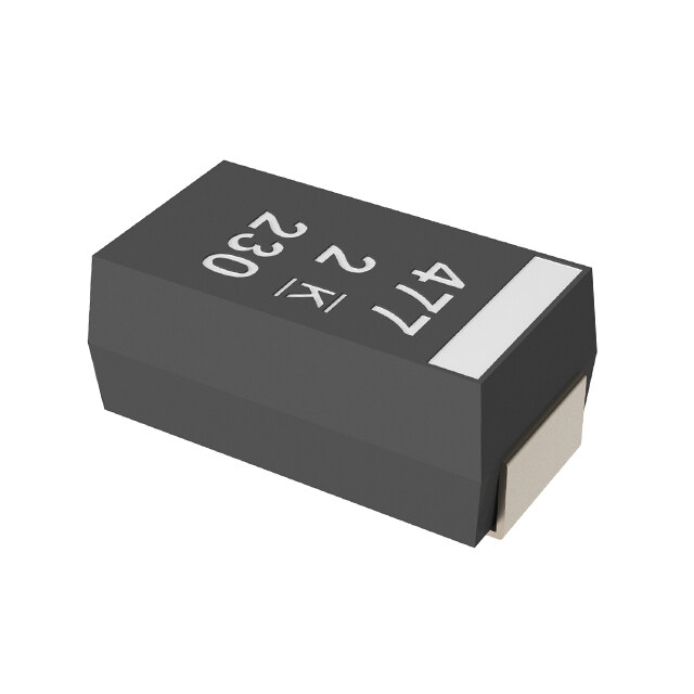
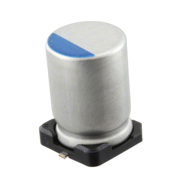
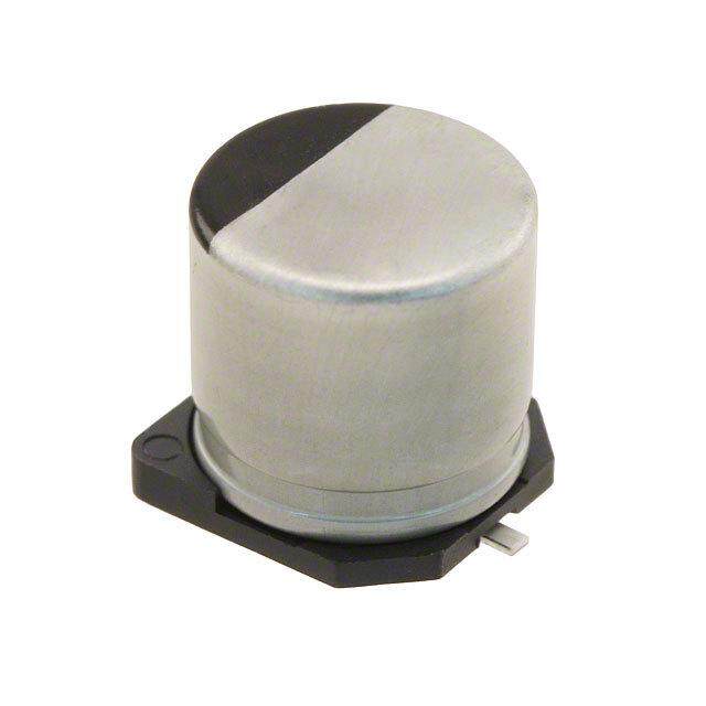
ICGOO电子元器件商城为您提供ECASD60J157M010K00由Murata设计生产,在icgoo商城现货销售,并且可以通过原厂、代理商等渠道进行代购。 ECASD60J157M010K00价格参考。MurataECASD60J157M010K00封装/规格:铝 - 聚合物电容器, 150µF 6.3V 铝聚合物电容器 2917(7343 公制) 10 毫欧 105°C 时为 1000 小时。您可以下载ECASD60J157M010K00参考资料、Datasheet数据手册功能说明书,资料中有ECASD60J157M010K00 详细功能的应用电路图电压和使用方法及教程。
Murata Electronics North America的ECASD60J157M010K00是一款铝-聚合物电容器,具有低ESR、高纹波电流能力和长寿命等特点。该型号的额定电压为6.3V,电容值为150μF,适用于对空间和性能都有较高要求的电子设备。

该电容器广泛应用于以下场景:

1. 电源管理电路:如DC-DC转换器、稳压电源中,用于滤波和稳定输出电压,提高电源效率和稳定性。

2. 主板与显卡:在计算机主板和GPU显卡上,用于提供稳定的电源滤波,支持高频开关电源的运行。

3. 通信设备:如基站、路由器和交换机中的电源模块,用于提高电源质量与系统可靠性。

4. 工业控制设备:如PLC、工业计算机和自动化控制系统中,用于抵抗恶劣环境下的电压波动。

5. 汽车电子系统:包括车载信息娱乐系统、驾驶辅助系统(ADAS)等,满足汽车电子对高可靠性和耐久性的要求。

6. 便携式电子产品:如高端智能手机、平板电脑和笔记本电脑,因其小型化和高性能特性而受到青睐。

该电容器采用表面贴装封装,适合自动化生产,同时具备良好的温度特性和寿命表现,适用于要求高稳定性和高效率的现代电子设备。
| 参数 | 数值 |
| 产品目录 | |
| 描述 | CAP ALUM 150UF 6.3V 20% SMD铝有机聚合物电容器 150uF 6.3volts 2.8mm ESR 10 mOhms |
| ESR | 10 mOhms |
| ESR(等效串联电阻) | 10 毫欧 |
| 产品分类 | |
| 品牌 | Murata Electronics |
| 产品手册 | |
| 产品图片 |
|
| rohs | 符合RoHS无铅 / 符合限制有害物质指令(RoHS)规范要求 |
| 产品系列 | 铝电解电容器,铝有机聚合物电容器,Murata Electronics ECASD60J157M010K00ECAS |
| 数据手册 | |
| 产品型号 | ECASD60J157M010K00 |
| 不同温度时的使用寿命 | 105°C 时为 1000 小时 |
| 产品 | Organic Polymer Aluminum - SMD Capacitors |
| 产品培训模块 | http://www.digikey.cn/PTM/IndividualPTM.page?site=cn&lang=zhs&ptm=24989http://www.digikey.cn/PTM/IndividualPTM.page?site=cn&lang=zhs&ptm=25728 |
| 产品目录绘图 |
|
| 产品目录页面 | |
| 产品种类 | 铝有机聚合物电容器 |
| 产品类型 | Molded |
| 其它名称 | 490-5466-6 |
| 包装 | Digi-Reel® |
| 商标 | Murata Electronics |
| 外壳代码-in | 2917 |
| 外壳宽度 | 4.3 mm |
| 外壳长度 | 7.3 mm |
| 外壳高度 | 1.9 mm |
| 大小/尺寸 | 0.287" 长 x 0.169" 宽(7.30mm x 4.30mm) |
| 安装类型 | 表面贴装 |
| 容差 | 20 % |
| 封装 | Reel |
| 封装/外壳 | 2917(7343 公制) |
| 封装/箱体 | 2917 (7343 metric) |
| 工作温度 | -40°C ~ 105°C |
| 工厂包装数量 | 2500 |
| 应用 | - |
| 引线间距 | - |
| 最大工作温度 | + 105 C |
| 最小工作温度 | - 40 C |
| 标准包装 | 1 |
| 特色产品 | http://www.digikey.com/cn/zh/ph/Murata/ECAS.html |
| 电压额定值DC | 6.3 V |
| 电容 | 150 uF |
| 端接类型 | SMD/SMT |
| 类型 | 聚合物 |
| 纹波电流 | 3 A |
| 表面贴装焊盘尺寸 | 0.287" 长 x 0.169" 宽(7.30mm x 4.30mm) |
| 阻抗 | - |
| 额定电压 | 6.3V |
| 高度 | 1.9 mm |
| 高度-安装(最大值) | 0.110"(2.80mm) |


- 商务部:美国ITC正式对集成电路等产品启动337调查
- 曝三星4nm工艺存在良率问题 高通将骁龙8 Gen1或转产台积电
- 太阳诱电将投资9.5亿元在常州建新厂生产MLCC 预计2023年完工
- 英特尔发布欧洲新工厂建设计划 深化IDM 2.0 战略
- 台积电先进制程称霸业界 有大客户加持明年业绩稳了
- 达到5530亿美元!SIA预计今年全球半导体销售额将创下新高
- 英特尔拟将自动驾驶子公司Mobileye上市 估值或超500亿美元
- 三星加码芯片和SET,合并消费电子和移动部门,撤换高东真等 CEO
- 三星电子宣布重大人事变动 还合并消费电子和移动部门
- 海关总署:前11个月进口集成电路产品价值2.52万亿元 增长14.8%
PDF Datasheet 数据手册内容提取
Polymer Aluminum Electrolytic Capacitors C90E.pdf Mar.23,2020
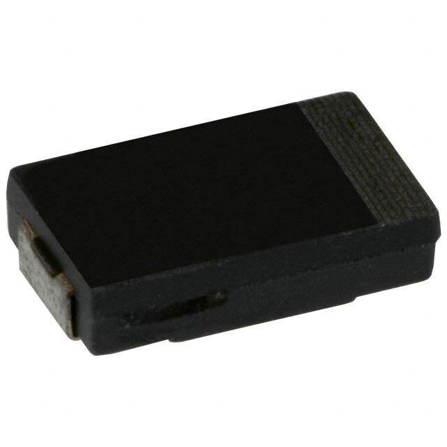
!Note(cid:70)(cid:3)Please read rating and !CAUTION (for storage, operating, rating, soldering, mounting and handling) in this catalog to prevent smoking and/or burning, etc. (cid:70)(cid:3)(cid:24)(cid:38)(cid:39)(cid:49)(cid:3)catalog has only typical specifications. Therefore, please approve our product specifications or transact the approval sheet for product specifications before ordering. Description Murata Manufacturing Co., Ltd.'s ECAS series of polymer aluminum electrolytic capacitors realize low ESR, low impedence and high capacitance by means of multilayered aluminum foil for anode, solid conductive polymer for cathode. With no bias characteristics and stable temperature characteristics, ECAS series have excellent performance in ripple absorption, smoothing and transient response suitable for numerous applications. Therefore, it is suitable for smoothing of input-output current of various power supply circuits, and the backup use over the load change of the CPU circumference. This contributes to reduction of the number of parts, or reduction of substrate area. Appearance External Dimensions L W Polarity Indicator Bar (+) Capacitance Code T Rated Voltage Code S S W1 (in mm) Case Size EIA Metric L W T W1 S D3 7343 7.3±0.3 4.3±0.2 1.4±0.1 2.4±0.2 1.3±0.2 Ex.) 220μF/2V D4 7343 7.3±0.3 4.3±0.2 1.9±0.1 2.4±0.2 1.3±0.2 D6 7343 7.3±0.3 4.3±0.2 2.8±0.3 2.4±0.2 1.3±0.2 Example of Structure Capacitor Model Etched Conductive Aluminum Foil Polymer Dielectric Al Oxidized Film Al Oxidized Film Epoxy Resin (+) (-) (+) (-) External External Electrodes Electrodes Anode Cathode Etched Aluminum foil Conductive Polymer Carbon Paste Silver Paste Capacitor Map (Cap & ESR) Specifications 100 Capacitance Range : 6.8 to 470μF Ta Capacitor Operating Temperature: -55°C to +125°C (MnO2) Rated Voltage : 2 to 25Vdc Al Capacitor ESR : 4.5 to 70mΩ 10 (Can Type/Electrolyte) z Ta Capacitor H Features k (Polymer) 00 1 1 t High capacitance and Low ESR a m) Stable capacitance with applied h R (o 0.1 DC voltage/temperature/high frequencies S Al Capacitor Excellent Ripple absorption, Smoothing, E (Can Type/Polymer) ECAS Transient response 0.01 Series No voltage derating required MLCC Polarity bar (positive) noted on product Surface mount construction 0.001 RoHS compliant 1 10 100 1000 10000 Halogen free Capacitance (μF) at 120Hz MSL 3 packaging 2 C90E.pdf Mar.23,2020
!Note(cid:70)(cid:3)Please read rating and !CAUTION (for storage, operating, rating, soldering, mounting and handling) in this catalog to prevent smoking and/or burning, etc. (cid:70)(cid:3)(cid:24)(cid:38)(cid:39)(cid:49)(cid:3)catalog has only typical specifications. Therefore, please approve our product specifications or transact the approval sheet for product specifications before ordering. Product Lineup Capacitance Value (μF) 6.8 10 15 22 33 47 68 100 150 220 330 470 2 D4 D4 D4 D4 D6 D6 0D 16 9 9 4.5/6 7 4.5/6 2.5 D4 D4 D6 D6 0E 4.5/6 9 4.5 6/9 dc) 4 D4 D4 D4 D4 D6 V 0G 20 16 16 9 10 e ( 6.3 D4 D4 D4 D4 D4 D4 D4 D6 D6 ag 0J 55 45 25 25 15 15 15 10 10 t ol 10 D4 D4 D4 D4 D3 D6 D4 V 1A 55 28 25 25 40 15 40 d e 16 D4 D4 D4 D6 D4 D3 D4 D4 at 1C 70 60 40 30 40 40 40 40 R 20 D4 1D 40 25 D3 D4 D3 D4 D3 D4 D4 1E 40 40 40 40 40 40 40 D4 Case Size Code max. temp. 105°C max. temp. 105°C, 125°C 6 ESR (mΩ) Characteristics Low ESR & Z DC Bias Characteristics 10 ECASD60D477M006K00 40 Representative Data Z ECASD60J157M010K00 ECASD61C226M030K00 20 1 %) e ( g R or Z (Ω) 0.1 nce Chan 0 S a -20 E cit a p 0.01 Ca -40 ESR 0.001 -60 1 10 100 1,000 10,000 100,000 0 25 50 75 100 Frequency (kHz) Bias Voltage/Rated Voltage (%) Temperature Characteristics of Capacitance 40 Representative Data 20 %) e ( g an 0 h C e c n a -20 cit a p a C -40 No Bias 50% of Rated Voltage -60 -50 -25 0 25 50 75 100 125 Temperature (°C) Design Support Tool - SimSurfing https://www.murata.com/simsurfing/ - Frequency responses (Z, ESR, ESL) of ECAS Series are available. - Netlist and S-parameter can be downloaded. - The software "SimSurfing" is also available for your simulation on the go where no internet connection is available. 3 C90E.pdf Mar.23,2020
!Note(cid:70)(cid:3)Please read rating and !CAUTION (for storage, operating, rating, soldering, mounting and handling) in this catalog to prevent smoking and/or burning, etc. (cid:70)(cid:3)(cid:24)(cid:38)(cid:39)(cid:49)(cid:3)catalog has only typical specifications. Therefore, please approve our product specifications or transact the approval sheet for product specifications before ordering. Applications Market Set/Application Overall Power Management Consumer Notebook/Ultrabook Ex.1) Power Supply line around IC etc... Digital TV (LCD/OLE) Audio/Projector Power CPU Set Top Box Supply ASIC Game Console FPGA Target etc Drone VR I IC on ESL(cid:70)ESR EEnntteerrpprriissee Server V V Multi Function Printer V Cap Enterprise Display (LCD) t t t Smart Meter Security (Camera/Home) Eliminates Ripple Stabilizes Eliminates High Frequency Smoothes Voltage Source Voltage Source Noise from IC Amusement POS/Handy Terminal Industrial Robotics Ex.2) USB bus power line PLC Peak Power Assistance Industrial PC UUSSBB23..00 5V USB Pfroowme Er CsuApSply Production Equipment/Module IC Port I Network Base Station (Wireless) Target Power supply G-PON (Optical) from Battery t Switch/Router Part Numbering (Part Number) 4Capacitance ECAS D4 0D 227 M 009 K 00 Expressed by three-digit numeric code. The unit is pico-farad (pF). 1 2 3 4 5 6 7 8 The first and second figures are significant digits, and the third figure expresses the number of zeros which follow the two numbers. Ex.) 1Series Code Capacitance 476 47μF Product ID 107 100μF ECAS Polymer AI Electrolytic Capacitor 227 220μF 2Dimension (LxWxT) (mm) 477 470μF Code L W T 5Capacitance Tolerance D3 7.3±0.3 4.3±0.2 1.4±0.1 Code Capacitance Tolerance D4 7.3±0.3 4.3±0.2 1.9±0.1 M ±20% D6 7.3±0.3 4.3±0.2 2.8±0.3 6ESR 3Rated Voltage Expressed by three-digit alphanumerics. The unit is milli-ohm (mΩ). Code Rated Voltage If there is a decimal point, it is expressed by the capital letter "R". Ex.) 0D DC 2V Code ESR 0E DC 2.5V 4R5 4.5mΩ 0G DC 4V 009 9mΩ 0J DC 6.3V 010 10mΩ 1A DC 10V 1C DC 16V 7Packaging 1D DC 20V Code Packaging 1E DC 25V K ø330mm Embossed Taping 8Individual Specification Code Expressed by two figures. 4 C90E.pdf Mar.23,2020
!Note(cid:70)(cid:3)Please read rating and !CAUTION (for storage, operating, rating, soldering, mounting and handling) in this catalog to prevent smoking and/or burning, etc. (cid:70)(cid:3)(cid:24)(cid:38)(cid:39)(cid:49)(cid:3)catalog has only typical specifications. Therefore, please approve our product specifications or transact the approval sheet for product specifications before ordering. Specifications and Test Methods No. Item Characteristics Test Conditions 1 Operating Temperature Range -55°C to +125°C — Series resistor : 1000 ohm Applied voltage: Rated Voltage Measuring after 2 minutes of application 2 Leakage Current <=The value of "Part Number Listing" Please conduct pre-conditioning below, if you have a doubt. Pre-conditioning: Apply rated DC voltage for 1 hour at 105°C through 1000 ohm series resistor. Then discharge and keep in the room temperature for 4 to 24 hours. 3 Capacitance Tolerance Please refer to "Part Number Listing" Measuring frequency : 120Hz ±10% Measuring circuit : Equivalent series circuit 4 Dissipation Factor <=0.06 Measuring voltage : +1Vr.m.s. Measuring temperature: 25°C Measuring frequency : 100kHz ±10% 5 ESR <=The value of "Part Number Listing" Measuring voltage : no more than +1Vr.m.s. Measuring temperature: 25°C 6 Allowable Ripple Current Please refer to "Part Number Listing" Measuring frequency: 100kHz ±10% Lead Free Solder : Sn/3.0Ag/0.5Cu More than 75% of each terminal face is Flux : Rosin 25%, IPA 75% 7 Solderability covered by new solder Solder temperature: 245 ±3°C Immersing time : 3 ±0.3s <=750% of initial specified value for 2V to 10V products Moisture Leakage Current <=300% of initial specified value Test temperature: 60±2°C Resistance for 12.5V to 25V products 8 Relative humidity : 90 to 95%RH Under No Capacitance Change -20% and +50% of initial measured value Test time : 500+24, -0h Bias Dissipation Factor <=0.12 Appearance No defects or abnormalities Moisture Leakage Current <=The value of "Part Number Listing" Test temperature: 60±2°C Resistance Capacitance Change -20% and +50% of initial measured value Relative humidity : 90 to 95%RH 9 Under Dissipation Factor <=0.12 Test time : 500+24, -0h Load Applied voltage : Rated Voltage Appearance No defects or abnormalities Leakage Current <=The value of "Part Number Listing" Capacitance Change ±10% of initial measured value Test temperature: 125±2°C 10 Shelf Life Dissipation Factor <=0.06 Test time : 1000+48, -0h Appearance No defects or abnormalities Leakage Current <=The value of "Part Number Listing" Test temperature: 125±2°C Capacitance Change ±20% of initial measured value 11 Endurance Test time : 1000+48, -0h Dissipation Factor <=0.06 Applied voltage : Rated Voltage Appearance No defects or abnormalities Leakage Current <=The value of "Part Number Listing" Temperature: +85°C for 2V to 10V products Capacitance Change ±10% of initial measured value Room temp. for 12.5V to 25V products Dissipation Factor <=0.06 Applied voltage: Rated voltage x1.25 for 2V to 10V products Rated voltage x1.15 for 12.5V to 25V products Current limiting resistance: 12 Surge 33 ohm (in series) for 2V to 10V products 1k ohm (in series) for 12.5V to 25V products Appearance No defects or abnormalities Discharge resistance: 33 ohm (in series) for 2V to 10V products 1k ohm (in series) for 12.5V to 25V products Charge on/off: 30 sec. each, 1000 times (The measurement condition in No.2 to 4 applies to No.8 to 12.) 5 C90E.pdf Mar.23,2020
!Note(cid:70)(cid:3)Please read rating and !CAUTION (for storage, operating, rating, soldering, mounting and handling) in this catalog to prevent smoking and/or burning, etc. (cid:70)(cid:3)(cid:24)(cid:38)(cid:39)(cid:49)(cid:3)catalog has only typical specifications. Therefore, please approve our product specifications or transact the approval sheet for product specifications before ordering. Recommended Reflow Profile Land Pattern Design 10sec. max. (Peak Temp.: 260°C max.) 250 Capacitor ure (°C) 200 40sec. max. 2.8 at 150 (230°C and over) er p m 120sec. max. Te 100 (150°C to 200°C) 4.0 50 Max temperature 260°C (245°C for some part numbers), two times. Please contact Murata for reflow condirtions except for the above. 8.8 0 (in mm) Time (sec.) Packaging 1 4.0±0.1 W 0. 1.75± 1.5+–00.1 2.0±0.1 DPol(a-r)ity 2.0±0.5 1 ø13±0.2 30. 0±0.5.5± B 2. B A 1 1.5+–00.25 (+) ø21±0.8 A C 8.0±0.1 (in mm) (in mm) W1 Case Cavity Size (mm) Minimum Qty. Reel Size Tape Width A B W W1 Size A* B* C* D* (pcs.) D3, D4 4.60 7.65 2.16 0.23 3,000 ø330 12 330.0±2.0 100.0±1.0 17.4±1.5 13.4±1.5 D6 4.60 7.65 3.20 0.27 2,500 * Nominal values Part Number Listing (Max. Operating Temperature: 105°C) CCaassee SSiizzee ESR Max. Ripple Min. Rated Cap. Leakage Cap. (mΩ) Current Packaging Part Number V(Vol.tDaCg)e (μF) Tole(%ra)nce CCooddee LL((mm xxmm WW)) ((mmTTmm)) 1/+0205k°HCz Cu(μrrAe)nt 1(A00rmkHs)z Qu(pacnst)ity ECASD40D107M016K00 2 100 ±20 D4 7343 1.9 16 20.0 2.0 3,000 ECASD40D157M009K00 2 150 ±20 D4 7343 1.9 9 30.0 3.0 3,000 ECASD40D227M009K00 2 220 ±20 D4 7343 1.9 9 44.0 3.0 3,000 ECASD40D337M4R5KA0 2 330 ±20 D4 7343 1.9 4.5 66.0 4.0 3,000 ECASD40D337M006KA0 2 330 ±20 D4 7343 1.9 6 66.0 3.0 3,000 ECASD60D337M007K00 2 330 ±20 D6 7343 2.8 7 66.0 3.5 2,500 ECASD60D477M4R5K00 2 470 ±20 D6 7343 2.8 4.5 94.0 4.0 2,500 ECASD60D477M006K00 2 470 ±20 D6 7343 2.8 6 94.0 3.5 2,500 ECASD40E337M4R5KA0 2.5 330 ±20 D4 7343 1.9 4.5 82.5 4.0 3,000 ECASD40E337M006KA0 2.5 330 ±20 D4 7343 1.9 6 82.5 3.0 3,000 ECASD40E337M009KA0 2.5 330 ±20 D4 7343 1.9 9 82.5 3.0 3,000 ECASD60E477M4R5K00 2.5 470 ±20 D6 7343 2.8 4.5 117.5 4.0 2,500 ECASD60E477M006K00 2.5 470 ±20 D6 7343 2.8 6 117.5 3.5 2,500 ECASD60E477M009K00 2.5 470 ±20 D6 7343 2.8 9 117.5 3.0 2,500 ECASD40G686M020K00 4 68 ±20 D4 7343 1.9 20 27.2 1.9 3,000 ECASD40G107M016K00 4 100 ±20 D4 7343 1.9 16 40.0 2.1 3,000 ECASD40G157M016K00 4 150 ±20 D4 7343 1.9 16 60.0 2.1 3,000 ECASD40G227M009K00 4 220 ±20 D4 7343 1.9 9 88.0 3.0 3,000 ECASD60G227M010K00 4 220 ±20 D6 7343 2.8 10 88.0 3.0 2,500 ECASD40J106M055K00 6.3 10 ±20 D4 7343 1.9 55 6.3 1.0 3,000 6 C90E.pdf Mar.23,2020
!Note(cid:70)(cid:3)Please read rating and !CAUTION (for storage, operating, rating, soldering, mounting and handling) in this catalog to prevent smoking and/or burning, etc. (cid:70)(cid:3)(cid:24)(cid:38)(cid:39)(cid:49)(cid:3)catalog has only typical specifications. Therefore, please approve our product specifications or transact the approval sheet for product specifications before ordering. CCaassee SSiizzee ESR Max. Ripple Min. Rated Cap. Leakage Cap. (mΩ) Current Packaging Part Number V(Vol.tDaCg)e (μF) Tole(%ra)nce CCooddee LL((mm xxmm WW)) ((mmTTmm)) 1/+0205k°HCz Cu(μrrAe)nt 1(A00rmkHs)z Qu(pacnst)ity ECASD40J226M045K00 6.3 22 ±20 D4 7343 1.9 45 13.9 1.0 3,000 ECASD40J336M025K00 6.3 33 ±20 D4 7343 1.9 25 20.8 1.8 3,000 ECASD40J476M025K00 6.3 47 ±20 D4 7343 1.9 25 29.7 1.8 3,000 ECASD40J686M015K00 6.3 68 ±20 D4 7343 1.9 15 42.9 2.0 3,000 ECASD40J107M015K00 6.3 100 ±20 D4 7343 1.9 15 63.0 2.0 3,000 ECASD40J157M015K00 6.3 150 ±20 D4 7343 1.9 15 94.5 2.0 3,000 ECASD60J157M010K00 6.3 150 ±20 D6 7343 2.8 10 94.5 3.0 2,500 ECASD60J227M010K00 6.3 220 ±20 D6 7343 2.8 10 138.6 3.0 2,500 ECASD41A106M055K00 10 10 ±20 D4 7343 1.9 55 10.0 1.0 3,000 ECASD41A226M028K00 10 22 ±20 D4 7343 1.9 28 22.0 1.6 3,000 ECASD41A336M025K00 10 33 ±20 D4 7343 1.9 25 33.0 1.8 3,000 ECASD41A476M025K00 10 47 ±20 D4 7343 1.9 25 47.0 1.8 3,000 ECASD31A686M040KA0 10 68 ±20 D3 7343 1.5 40 204.0 1.6 3,000 ECASD61A686M015K00 10 68 ±20 D6 7343 2.8 15 68.0 2.0 2,500 ECASD41A107M040KA0 10 100 ±20 D4 7343 1.9 40 300.0 1.6 3,000 ECASD41C685M070K00 16 6.8 ±20 D4 7343 1.9 70 10.9 1.0 3,000 ECASD41C106M060K00 16 10 ±20 D4 7343 1.9 60 16.0 1.0 3,000 ECASD41C156M040K00 16 15 ±20 D4 7343 1.9 40 24.0 1.0 3,000 ECASD61C226M030K00 16 22 ±20 D6 7343 2.8 30 35.2 1.6 2,500 ECASD41C336M040KA0 16 33 ±20 D4 7343 1.9 40 158.4 1.6 3,000 ECASD31C476M040KA0 16 47 ±20 D3 7343 1.5 40 225.6 1.6 3,000 ECASD41C476M040KA0 16 47 ±20 D4 7343 1.9 40 225.6 1.6 3,000 ECASD41C686M040KA0 16 68 ±20 D4 7343 1.9 40 326.4 1.6 3,000 ECASD41D476M040KA0 20 47 ±20 D4 7343 1.9 40 282.0 1.6 3,000 ECASD31E106M040KA0 25 10 ±20 D3 7343 1.5 40 75.0 1.6 3,000 ECASD41E106M040KA0 25 10 ±20 D4 7343 1.9 40 75.0 1.6 3,000 ECASD31E156M040KA0 25 15 ±20 D3 7343 1.5 40 112.5 1.6 3,000 ECASD41E156M040KA0 25 15 ±20 D4 7343 1.9 40 112.5 1.6 3,000 ECASD31E226M040KA0 25 22 ±20 D3 7343 1.5 40 165.0 1.6 3,000 ECASD41E226M040KA0 25 22 ±20 D4 7343 1.9 40 165.0 1.6 3,000 ECASD41E336M040KA0 25 33 ±20 D4 7343 1.9 40 247.5 1.6 3,000 Part Number Listing (Max. Operating Temperature: 125°C) CCaassee SSiizzee ESR Max. Ripple Min. Rated Cap. Leakage Cap. (mΩ) Current Packaging Part Number V(Vol.tDaCg)e (μF) Tole(%ra)nce CCooddee LL((mm xxmm WW)) ((mmTTmm)) 1/+0205k°HCz Cu(μrrAe)nt 1(A00rmkHs)z Qu(pacnst)ity ECASD40E337M009KH0 2.5 330 ±20 D4 7343 1.9 9 82.5 3.5 3,000 ECASD60E477M4R5KH0 2.5 470 ±20 D6 7343 2.8 4.5 117.5 4.0 2,500 ECASD40J107M015KH0 6.3 100 ±20 D4 7343 1.9 15 63.0 2.0 3,000 ECASD41A107M040KH0 10 100 ±20 D4 7343 1.9 40 300.0 1.6 3,000 ECASD31C476M040KH0 16 47 ±20 D3 7343 1.5 40 225.6 1.6 3,000 ECASD41C476M040KH0 16 47 ±20 D4 7343 1.9 40 225.6 1.6 3,000 ECASD41C686M040KH0 16 68 ±20 D4 7343 1.9 40 326.4 1.6 3,000 ECASD41D476M040KH0 20 47 ±20 D4 7343 1.9 40 282.0 1.6 3,000 ECASD31E106M040KH0 25 10 ±20 D3 7343 1.5 40 75.0 1.6 3,000 ECASD41E106M040KH0 25 10 ±20 D4 7343 1.9 40 75.0 1.6 3,000 ECASD31E156M040KH0 25 15 ±20 D3 7343 1.5 40 112.5 1.6 3,000 ECASD41E156M040KH0 25 15 ±20 D4 7343 1.9 40 112.5 1.6 3,000 ECASD31E226M040KH0 25 22 ±20 D3 7343 1.5 40 165.0 1.6 3,000 ECASD41E226M040KH0 25 22 ±20 D4 7343 1.9 40 165.0 1.6 3,000 ECASD41E336M040KH0 25 33 ±20 D4 7343 1.9 40 247.5 1.6 3,000 7 C90E.pdf Mar.23,2020
!Note(cid:70)(cid:3)Please read rating and !CAUTION (for storage, operating, rating, soldering, mounting and handling) in this catalog to prevent smoking and/or burning, etc. (cid:70)(cid:3)(cid:24)(cid:38)(cid:39)(cid:49)(cid:3)catalog has only typical specifications. Therefore, please approve our product specifications or transact the approval sheet for product specifications before ordering. Cautions for Use Cautions <1> Prohibited Circuits For Use Do not use the capacitor with the following circuits. n n n 1 Time-constant circuit 2 Coupling circuits 3 2 or more capacitors connected serially n 4 Circuit which are greatly affected by leakage current <2> Polarity Polymer aluminum electrolytic capacitor is polarized. Please not to reverse the polarity when using. If reverse voltage is applied even momentary, it may damage the oxide film and the capacitor itself. <3> Operating Voltage When DC-rated capacitors are to be used in AC or ripple current circuits, be sure to maintain the Vp-p value of the applied voltage or the Vo-p which contains DC bias within the rated voltage range. When the voltage is applied to the circuit, starting or stopping may generate irregular voltage for a transit period because of resonance or switching. Be sure to use a capacitor with a rated voltage range that includes these irregular voltages. <4> Inrush Current Extreme inrush current may cause short circuit or leakage current increase. If the inrush current exceeds 20A, adding protection circuit is recommended. <5> Allowable Ripple Current Please not to apply ripple current exceeding the allowable value specified in this document. If excessive current is applied, it may generate heat and the heat may damage the capacitor. The sum of DC voltage and the peak AC voltage shall not exceed the rated voltage. The sum of the DC voltage and the peak AC voltage shall not allow a voltage reversal. <6> Operating Temperature The operating temperature limit depends on the capacitor. n 1 Do not apply temperature exceeding the upper operating temperature. It is necessary to select a capacitor with a suitable rated temperature that will cover the operating temperature range. Also it is necessary to consider the temperature distribution in equipment and the seasonal temperature variable factor. n 2 Consider the self-heating of the capacitor. The surface temperature of the capacitor shall be the upper operating temperature or less when including the self-heating factors. <7> Reflow Soldering Please not to apply excessive force to the capacitor during insertion as well as after soldering. The excessive force may result in damage to electrode terminals and/or degradation of electrical performance. <8> Conditions for soldering with iron Temperature of iron tip: 350 ±5°C max. (70W max.) Soldering time: Within 3 sec. for each terminal Times: 1 time only for each terminal Please do not touch the capacitor body with iron or apply excessive force to the capacitor while soldering. Do not reuse the capacitor once removed from a printed circuit board. <9> Operating Environment Confirm the environment in which the equipment will operate is under the specified conditions. Do not use the equipment under the following environments. n 1 Being spattered with water or oil. n 2 Being exposed to direct sunlight. n 3 Being exposed to Ozone, ultraviolet rays or radiation. n 4 Being exposed to toxic gas (e.g., hydrogen sulfide, sulfur dioxide, chlorine, ammonia gas, etc.) n n 5 Being exposed to excessive vibrations or mechanical shocks. 6 Being exposed to condensable environments. Storage Conditions <1> Term of warranty for this product is two years after packaging in a moisture-proof bag, under the conditions below with sealed packaging. Recommended storage environment Room temperature: 5-30°C Humidity: no more than 60%RH <2> Polymer aluminum electrolytic capacitors should not be stored in an atmosphere consisting of corrosive gas (e.g., hydrogen sulfide, sulfur dioxide, chlorine, ammonia gas, etc.). <3> Polymer aluminum electrolytic capacitors should be stored in a dry atmosphere, avoiding direct sunlight and condensation. If capacitors are kept at a higher humidity, the following problems may occur: n 1 Leakage current will increase at the beginning of use and damage the circuit. n 2 Moisture absorbed in a resin will evaporate and expand with heat of mounting and damage the mold resin. <4> Please confirm a dry state with a humidity indicator card after open immediately. If 20% indication was in a pink state after opened, it is recommended to bake under the conditions below. <5> The capacitors should be kept dry using desiccators or any other methods after unsealing the moisture-proof packaging. If more than one week has passed under the recommended storage environment specified above after unsealing the packaging, it is recommended to bake under the conditions below. Recommended baking conditions Temperature: 60 (+0, -5) °C Time: 168 hours <6> This product meets MSL-3. EU RoHS Compliant (cid:70)(cid:3)All the products in this catalog comply with EU RoHS. (cid:70)(cid:3)EU RoHS is "the European Directive 2011/65/EU on the Restriction of the Use of Certain Hazardous Substances in Electrical and Electronic Equipment." (cid:70)(cid:3)For more details, please refer to our website 'Murata's Approach for EU RoHS' (http://www.murata.com/en-us/support/compliance/rohs). 8 C90E.pdf Mar.23,2020
Cat. No. C90E-5 Global Locations For details please visit www.murata.com Note 1 Export Control 2 Please contact our sales representatives or 3 Product specifi cations in this catalog are as of product engineers before using the products in March 2020. They are subject to change or For customers outside Japan: this catalog for the applications listed below, our products in it may be discontinued without No Murata products should be used or which require especially high reliability for the advance notice. Please check with our sales sold, through any channels, for use in the prevention of defects which might directly representatives or product engineers before design, development, production, utilization, damage a third party’s life, body or property, or ordering. If there are any questions, please contact maintenance or operation of, or otherwise when one of our products is intended for use our sales representatives or product engineers. contribution to (1) any weapons (Weapons of in applications other than those specified in Mass Destruction [nuclear, chemical or biological this catalog. 4 Please read rating and CAUTION (for storage, weapons or missiles] or conventional weapons) operating, rating, soldering, mounting and or (2) goods or systems specially designed or 1 Aircraft equipment handling) in this catalog to prevent smoking intended for military end-use or utilization by 2 Aerospace equipment and/or burning, etc. military end-users. 3 Undersea equipment 5 This catalog has only typical specifi cations. For customers in Japan: Therefore, please approve our product 4 Power plant equipment specifi cations or transact the approval sheet For products which are controlled items subject for product specifi cations before ordering. to the “Foreign Exchange and Foreign Trade Law” 5 Medical equipment of Japan, the export license specifi ed by the law 6 Please note that unless otherwise specifi ed, we is required for export. 6 Transportation equipment (vehicles, trains, shall assume no responsibility whatsoever for any ships, etc.) confl ict or dispute that may occur in connection 7 Traffi c signal equipment with the eff ect of our and/or a third party’s intellectual property rights and other related 8 Disaster prevention / crime prevention rights in consideration of your use of our products equipment and/or information described or contained in our catalogs. In this connection, no representation 9 Data-processing equipment shall be made to the eff ect that any third parties are authorized to use the rights mentioned above 10 Application of similar complexity and/or under licenses without our consent. reliability requirements to the applications listed above 7 No ozone depleting substances (ODS) under the Montreal Protocol are used in our manufacturing process. Murata Manufacturing Co., Ltd. www.murata.com C90E.pdf Mar.23,2020