ICGOO在线商城 > 集成电路(IC) > 接口 - 驱动器,接收器,收发器 > DS36276MX/NOPB
- 型号: DS36276MX/NOPB
- 制造商: Texas Instruments
- 库位|库存: xxxx|xxxx
- 要求:
| 数量阶梯 | 香港交货 | 国内含税 |
| +xxxx | $xxxx | ¥xxxx |
查看当月历史价格
查看今年历史价格
DS36276MX/NOPB产品简介:
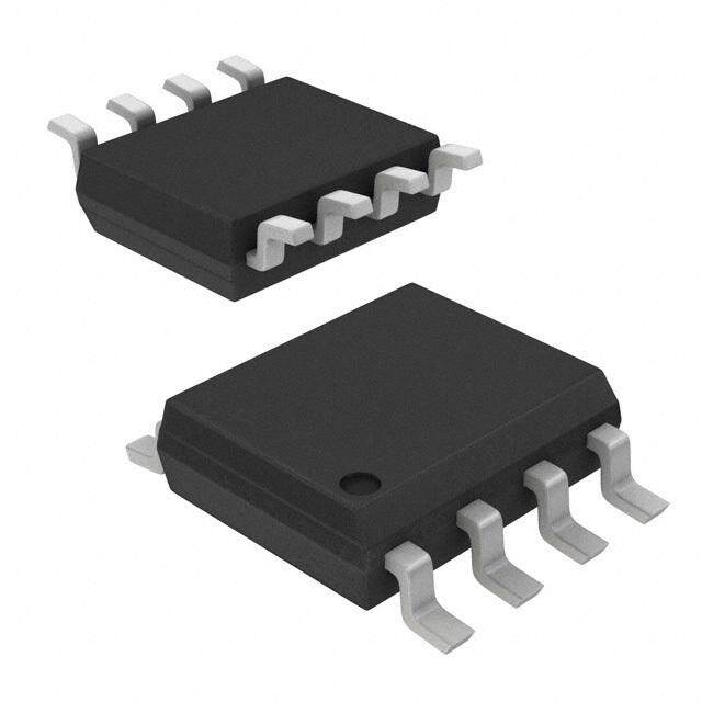
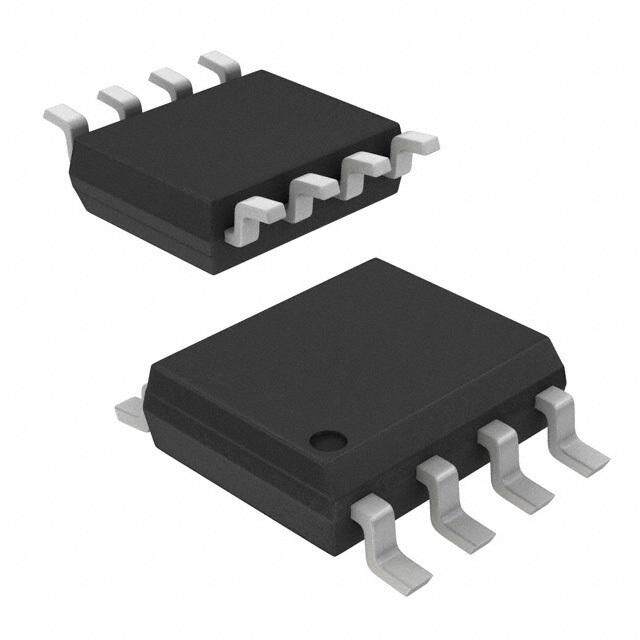
ICGOO电子元器件商城为您提供DS36276MX/NOPB由Texas Instruments设计生产,在icgoo商城现货销售,并且可以通过原厂、代理商等渠道进行代购。 DS36276MX/NOPB价格参考。Texas InstrumentsDS36276MX/NOPB封装/规格:接口 - 驱动器,接收器,收发器, 1/1 Transceiver Half RS422, RS485 8-SOIC。您可以下载DS36276MX/NOPB参考资料、Datasheet数据手册功能说明书,资料中有DS36276MX/NOPB 详细功能的应用电路图电压和使用方法及教程。
DS36276MX/NOPB是Texas Instruments(德州仪器)生产的一款双路RS-422/RS-485通信接口收发器,属于接口驱动器、接收器、收发器类别。该器件采用SOIC-8封装,符合工业标准引脚配置,支持宽温度范围,适用于严苛工业环境。

其主要应用场景包括工业自动化控制系统、过程控制设备和工厂自动化网络,常用于PLC(可编程逻辑控制器)、HMI(人机界面)和远程I/O模块之间的串行通信。由于支持高速数据传输(最高可达10 Mbps),DS36276MX/NOPB也广泛应用于需要可靠长距离通信的数据采集系统和工业现场总线系统中。

此外,该器件具备高抗干扰能力和热关断保护功能,适合在电磁干扰较强的环境中稳定运行,如电机控制中心、电力监控系统和楼宇自动化系统。其无铅环保设计(NOPB标识)也符合现代电子产品的环保要求。

综上所述,DS36276MX/NOPB适用于各类要求高可靠性、抗噪声能力强的工业通信场合,特别是在使用RS-422或RS-485协议进行点对点或多点数据传输的系统中表现优异。
| 参数 | 数值 |
| 产品目录 | 集成电路 (IC) |
| 描述 | IC TRANSCEIVER MUTLIPOINT 8-SOIC |
| 产品分类 | |
| 品牌 | Texas Instruments |
| 数据手册 | |
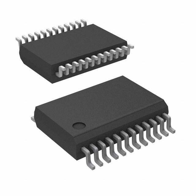
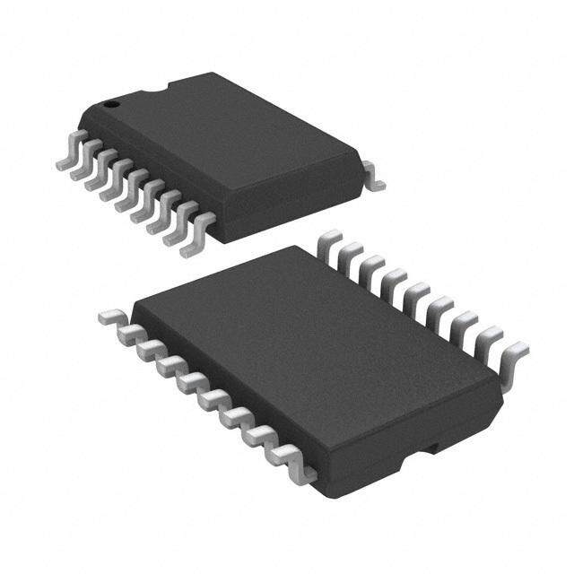
| 产品图片 |
|
| 产品型号 | DS36276MX/NOPB |
| rohs | 无铅 / 符合限制有害物质指令(RoHS)规范要求 |
| 产品系列 | - |
| 供应商器件封装 | 8-SOIC |
| 其它名称 | 296-35372-6 |
| 包装 | Digi-Reel® |
| 协议 | RS422,RS485 |
| 双工 | 半 |
| 安装类型 | 表面贴装 |
| 封装/外壳 | 8-SOIC(0.154",3.90mm 宽) |
| 工作温度 | 0°C ~ 70°C |
| 接收器滞后 | 50mV |
| 数据速率 | - |
| 标准包装 | 1 |
| 电压-电源 | 4.75 V ~ 5.25 V |
| 类型 | 收发器 |
| 驱动器/接收器数 | 1/1 |




- 商务部:美国ITC正式对集成电路等产品启动337调查
- 曝三星4nm工艺存在良率问题 高通将骁龙8 Gen1或转产台积电
- 太阳诱电将投资9.5亿元在常州建新厂生产MLCC 预计2023年完工
- 英特尔发布欧洲新工厂建设计划 深化IDM 2.0 战略
- 台积电先进制程称霸业界 有大客户加持明年业绩稳了
- 达到5530亿美元!SIA预计今年全球半导体销售额将创下新高
- 英特尔拟将自动驾驶子公司Mobileye上市 估值或超500亿美元
- 三星加码芯片和SET,合并消费电子和移动部门,撤换高东真等 CEO
- 三星电子宣布重大人事变动 还合并消费电子和移动部门
- 海关总署:前11个月进口集成电路产品价值2.52万亿元 增长14.8%




PDF Datasheet 数据手册内容提取
DS36276 DS36276 FAILSAFE Multipoint Transceiver Literature Number: SNLS085A
D July1998 S 3 6 2 7 6 DS36276 F A FAILSAFE Multipoint Transceiver I L S General Description Features A TheDS36276FAILSAFEMultipointTransceiverisdesigned n FAILSAFEreceiver,RO=HIGHfor: F for use on bi-directional differential busses. It is compatible —OPENinputs E withexistingTIA/EIA-485transceivers,however,itoffersan —Terminatedinputs M additionalfeaturenotsupportedbystandardtransceivers. —SHORTEDinputs u The FAILSAFE feature guarantees the receiver output to a n Compatiblewithpopularinterfacestandards: l knownstatewhentheInterfaceisinthefollowingconditions: —TIA/EIA-485(RS-485) ti p Floating Line, Idle Line (no active drivers), and Line Fault —TIA/EIA-422-A(RS-422-A) o conditions(openorshort).ThereceiveroutputisinaHIGH —CCITTRecommendationV.11 i stateforthefollowingconditions:OPENInputs,Terminated n Bi-DirectionalTransceiver n Inputs(50W ),andSHORTEDInputs. —Designedformultipointtransmission t T FAILSAFEisahighlydesirablefeaturewhenthetransceiv- n Separatedriverinput,driverenable,receiverenable, r ersareusedwithAsynchronousControllerssuchasUARTs. andreceiveroutputformaximumflexibility a n n Widebuscommonmoderange s —(−7Vto+12V) c n Pincompatiblewith:DS75176B,DS96176,DS3695and e SN75176AandB iv n AvailableinSOICpackage e r Connection and Driver Logic Diagram Inputs Outputs RE DE DI DO/RI DO/RI X H H H L X H L L H X L X Z Z Receiver Inputs Output DS011383-1 RE DE RI–RI RO OrderNumberDS36276M L L ‡ 0V H SeeNSPackageNumberM08A L L £ −500mV L H X X Z Receiver FAILSAFE Inputs Output RE DE RI–RI RO L L SHORTED H L L OPEN H H X X Z TRI-STATE®isaregisteredtrademarkofNationalSemiconductorCorporation. ©2001NationalSemiconductorCorporation DS011383 www.national.com
6 7 2 Absolute Maximum Ratings (Note 1) LeadTemperature(Soldering4 6 3 sec.) 260˚C S If Military/Aerospace specified devices are required, D pleasecontacttheNationalSemiconductorSalesOffice/ MaxJunctionTemperature 150˚C Distributorsforavailabilityandspecifications. ESDRating(HBM,1.5kW ,100 pF) ‡ 6.0kV SupplyVoltage(V ) 7V CC InputVoltage(DE,RE,andDI) 5.5V Recommended Operating DriverOutputVoltage/ Conditions ReceiverInputVoltage −10Vto+15V ReceiverOutputVoltage(RO) 5.5V Min Max Units MaximumPackagePowerDissipation @ +25˚C SupplyVoltage,VCC 4.75 5.25 V MPackage BusVoltage −7 +12 V (derate5.8mW/˚Cabove OperatingTemperature(T ) A +25˚C) 726mW DS36276 0 +70 ˚C StorageTemperatureRange −65˚Cto+150˚C Electrical Characteristics (Notes 2, 4) OverrecommendedSupplyVoltageandOperatingTemperatureranges,unlessotherwisespecified. Symbol Parameter Conditions Min Typ Max Units DRIVERCHARACTERISTICS V DifferentialOutputVoltage I =0mA(NoLoad) 1.5 4.8 6.0 V OD O V OutputVoltage I =0mA(OutputtoGND) 0 6.0 V oDO O V OutputVoltage 0 6.0 V oDO V DifferentialOutputVoltage R =54W (485) (Figure1) 1.5 2.0 5.0 V T1 L (TerminationLoad) R =100W (422) 2.0 2.3 5.0 V L D V BalanceofV R =54W (Note3) −0.2 0.07 +0.2 V T1 T1 L |VT1|−|VT1| RL=100W −0.2 0.07 +0.2 V V DriverCommonMode R =54W (Figure1) 0 2.5 3.0 V OS L OutputVoltage R =100W 0 2.3 3.0 V L D V BalanceofV R =54W (Note3) −0.2 0.08 +0.2 V OS OS L |VOS|−|VOS| RL=100W −0.2 0.08 +0.2 V I DriverShort-Circuit V =+12V (Figure3) 134 290 mA OSD O OutputCurrent V =V 140 mA O CC V =0V −140 mA O V =−7V −180 −290 mA O RECEIVERCHARACTERISTICS V DifferentialInputHigh V =V ,I =−0.4mA TH O OH O −0.18 0 V ThresholdVoltage(Note5) −7V£ V £ +12V CM V DifferentialInputLow V =V ,I =8.0mA TL O OL O −0.5 −0.23 V ThresholdVoltage(Note5) −7V£ V £ +12V CM V Hysteresis(Note6) V =0V 50 mV HST CM I LineInputCurrent OtherInput=0V V =+12V 0.7 1.0 mA IN I (VCC=4.75V,5.25V,0V) DE=VIH(Note7) VI=−7V −0.5 −0.8 mA I ShortCircuitCurrent V =0V RO −5.0 −30 −85 mA OSR O I TRI-STATE® LeakageCurrent V =0.4to2.4V −20 +20 µA OZ O V OutputHighVoltage V =0V,I =−0.4mA 2.5 3.5 V OH ID OH (Figure12) V =OPEN,I =−0.4mA 2.5 3.5 V ID OH V OutputLowVoltage V =−0.5V,I =+8mA 0.25 0.6 V OL ID OL (Figure12) V =−0.5V,I =+16mA 0.35 0.7 V ID OL R InputResistance 12 19 kW IN www.national.com 2
D Electrical Characteristics S (Notes 2, 4) (Continued) 3 6 2 OverrecommendedSupplyVoltageandOperatingTemperatureranges,unlessotherwisespecified. 7 6 Symbol Parameter Conditions Min Typ Max Units DEVICECHARACTERISTICS V HighLevelInputVoltage DE, 2.0 V V IH CC V LowLevelInputVoltage RE, GND 0.8 V IL or I HighLevelInputCurrent V =2.4V 20 µA IH IH DI I LowLevelInputCurrent V =0.4V −100 µA IL IL V InputClampVoltage I =−18mA −0.75 −1.5 V CL CL I OutputLowVoltage DE=3V,RE=0V,DI=0V 42 60 mA CC I SupplyCurrent DE=0V,RE=0V,DI=0V 28 45 mA CCR (NoLoad) I DE=3V,RE=3V,DI=0V 43 60 mA CCD I DE=0V,RE=3V,DI=0V 31 50 mA CCX Switching Characteristics (Note 4) OverrecommendedSupplyVoltageandOperatingTemperatureranges,unlessotherwisespecified. Symbol Parameter Conditions Min Typ Max Units DRIVERCHARACTERISTICS t Diff.Prop.DelayLowtoHigh R =54W 7 21 60 ns PLHD L tPHLD Diff.Prop.DelayHightoLow CL=50pF 7 19 60 ns C =50pF t Diff.Skew(|t –t |) D 2 10 ns SKD PLHD PHLD (Figures4,5) t Diff.RiseTime 12 50 ns r t Diff.FallTime 12 50 ns f t Prop.DelayLowtoHigh R =27W ,C =15pF 22 45 ns PLH L L t Prop.DelayHightoLow (Figures6,7) 22 45 ns PHL t EnableTimeZtoHigh R =110W 32 55 ns PZH L tPZL EnableTimeZtoLow CL=50pF 32 65 ns (Figure8–Figure11) t DisableTimeHightoZ 22 55 ns PHZ t DisableTimeLowtoZ 16 55 ns PLZ RECEIVERCHARACTERISTICS t Prop.DelayLowtoHigh V =−1.5Vto+1.5V 15 40 70 ns PLH ID tPHL Prop.DelayHightoLow CL=15pF 15 42 70 ns (Figures13,14) t Skew(|t –t |) 2 15 ns SK PLH PHL t EnableTimeZtoHigh C =15pF 15 50 ns PZH L t EnableTimeZtoLow (Figures15,16) 17 50 ns PZL t DisableTimeHightoZ 24 50 ns PHZ t DisableTimeLowtoZ 19 50 ns PLZ Note1: “AbsoluteMaximumRatings”arethosevaluesbeyondwhichthesafetyofthedevicecannotbeguaranteed.Theyarenotmeanttoimplythatthedevices shouldbeoperatedattheselimits.Thetablesof“ElectricalCharacteristics”specifyconditionsfordeviceoperation. Note2: Currentintodevicepinsisdefinedaspositive.Currentoutofdevicepinsisdefinedasnegative.Allvoltagesarereferencedtogroundunlessotherwise specified. Note3: D |VT1|andD |VOS|arechangesinmagnitudeofVT1andVOS,respectively,thatoccurwhentheinputchangesstate. Note4: AlltypicalsaregivenforVCC=5.0VandTA=+25˚C. Note5: Thresholdparameterlimitsspecifiedasanalgebraicvalueratherthanbymagnitude. Note6: HysteresisdefinedasVHST=VTH−VTL. Note7: IINincludesthereceiverinputcurrentanddriverTRI-STATEleakagecurrent. 3 www.national.com
6 7 2 Parameter Measurement Information 6 3 S D DS011383-2 FIGURE1.DriverV andV TestCircuit T1 OS DS011383-3 FIGURE2.DriverV andV TestCircuit OH OL DS011383-4 FIGURE3.DriverShortCircuitTestCircuit DS011383-5 FIGURE4.DriverDifferentialPropagationDelayandTransitionTimeTestCircuit www.national.com 4
D Parameter Measurement Information S (Continued) 3 6 2 7 6 DS011383-6 FIGURE5.DriverDifferentialPropagationDelaysandTransitionTimes DS011383-7 FIGURE6.DriverPropagationDelayTestCircuit DS011383-8 FIGURE7.DriverPropagationDelays DS011383-9 S1toDOforDI=3V S1toDOforDI=0V FIGURE8.DriverTRl-STATETestCircuit(t ,t ) PZH PHZ 5 www.national.com
6 7 2 Parameter Measurement Information (Continued) 6 3 S D DS011383-10 FIGURE9.DriverTRI-STATEDelays(t ,t ) PZH PHZ DS011383-11 S1toDOforDI=0V S1toDOforDI=3V FIGURE10.DriverTRI-STATETestCircuit(t ,t ) PZL PLZ DS011383-12 FIGURE11.DriverTRl-STATEDelays(t ,t ) PZL PLZ DS011383-13 FIGURE12.ReceiverV andV OH OL DS011383-14 FIGURE13.ReceiverPropagationDelayTestCircuit www.national.com 6
D Parameter Measurement Information S (Continued) 3 6 2 7 6 DS011383-15 FIGURE14.ReceiverPropagationDelays DS011383-16 FIGURE15.ReceiverTRI-STATEDelayTestCircuit DS011383-17 DS011383-18 S11.5V S1−1.5V S2OPEN S2CLOSED S3CLOSED S3OPEN DS011383-19 DS011383-20 S11.5V S1−1.5V S2CLOSED S2CLOSED S3CLOSED S3CLOSED Note8: Theinputpulseissuppliedbyageneratorhavingthefollowingcharacteristics:f=1.0MHz,50%dutycycle,trandtf<6.0ns,ZO=50W . Note9: CLincludesprobeandstraycapacitance. Note10: Diodesare1N916orequivalent. FIGURE16.ReceiverEnableandDisableTiming 7 www.national.com
6 7 2 Typical Performance Characteristics 6 3 S D DifferentialOutputVoltage DifferentialOutputVoltage vsOutputCurrent vsOutputCurrent DS011383-21 DS011383-22 DriverV vsI vsV DriverV vsI vsTemperature OH OH CC OH OH DS011383-23 DS011383-24 DriverV vsI vsV DriverV vsI vsTemperature OL OL CC OL OL DS011383-25 DS011383-26 www.national.com 8
D Typical Performance Characteristics S (Continued) 3 6 2 7 6 ReceiverV vsI vsV ReceiverV vsI vsTemperature OH OH CC OH OH DS011383-27 DS011383-28 ReceiverV vsI vsV ReceiverV vsI vsTemperature OL OL CC OL OL DS011383-29 DS011383-30 SupplyCurrrentvsSupplyVoltage SupplyCurrentvsTemperature DS011383-31 DS011383-32 9 www.national.com
6 7 2 Typical Performance Characteristics (Continued) 6 3 S D VoltageOutputvsVoltageInput (Hysteresis) DS011383-33 www.national.com 10
D Physical Dimensions inches (millimeters) unless otherwise noted S 3 6 2 7 6 F A I L S A F E M u l t i p o i n t T r a n s c e OrderNumberDS36276M i NSPackageNumberM08A v e r LIFESUPPORTPOLICY NATIONAL’S PRODUCTS ARE NOT AUTHORIZED FOR USE AS CRITICAL COMPONENTS IN LIFE SUPPORT DEVICES OR SYSTEMS WITHOUT THE EXPRESS WRITTEN APPROVAL OF THE PRESIDENT AND GENERAL COUNSELOFNATIONALSEMICONDUCTORCORPORATION.Asusedherein: 1. Life support devices or systems are devices or 2. A critical component is any component of a life systems which, (a) are intended for surgical implant support device or system whose failure to perform into the body, or (b) support or sustain life, and can be reasonably expected to cause the failure of whose failure to perform when properly used in the life support device or system, or to affect its accordance with instructions for use provided in the safetyoreffectiveness. labeling, can be reasonably expected to result in a significantinjurytotheuser. NationalSemiconductor NationalSemiconductor NationalSemiconductor NationalSemiconductor Corporation Europe AsiaPacificCustomer JapanLtd. Americas Fax: +49(0)180-5308586 ResponseGroup Tel: 81-3-5639-7560 Email:support@nsc.com Email: europe.support@nsc.com Tel:65-2544466 Fax:81-3-5639-7507 Deutsch Tel: +49(0)6995086208 Fax:65-2504466 English Tel: +44(0)8702402171 Email:ap.support@nsc.com www.national.com FrançaisTel: +33(0)141918790 Nationaldoesnotassumeanyresponsibilityforuseofanycircuitrydescribed,nocircuitpatentlicensesareimpliedandNationalreservestherightatanytimewithoutnoticetochangesaidcircuitryandspecifications.
IMPORTANTNOTICE TexasInstrumentsIncorporatedanditssubsidiaries(TI)reservetherighttomakecorrections,modifications,enhancements,improvements, andotherchangestoitsproductsandservicesatanytimeandtodiscontinueanyproductorservicewithoutnotice.Customersshould obtainthelatestrelevantinformationbeforeplacingordersandshouldverifythatsuchinformationiscurrentandcomplete.Allproductsare soldsubjecttoTI’stermsandconditionsofsalesuppliedatthetimeoforderacknowledgment. TIwarrantsperformanceofitshardwareproductstothespecificationsapplicableatthetimeofsaleinaccordancewithTI’sstandard warranty.TestingandotherqualitycontroltechniquesareusedtotheextentTIdeemsnecessarytosupportthiswarranty.Exceptwhere mandatedbygovernmentrequirements,testingofallparametersofeachproductisnotnecessarilyperformed. TIassumesnoliabilityforapplicationsassistanceorcustomerproductdesign.Customersareresponsiblefortheirproductsand applicationsusingTIcomponents.Tominimizetherisksassociatedwithcustomerproductsandapplications,customersshouldprovide adequatedesignandoperatingsafeguards. TIdoesnotwarrantorrepresentthatanylicense,eitherexpressorimplied,isgrantedunderanyTIpatentright,copyright,maskworkright, orotherTIintellectualpropertyrightrelatingtoanycombination,machine,orprocessinwhichTIproductsorservicesareused.Information publishedbyTIregardingthird-partyproductsorservicesdoesnotconstitutealicensefromTItousesuchproductsorservicesora warrantyorendorsementthereof.Useofsuchinformationmayrequirealicensefromathirdpartyunderthepatentsorotherintellectual propertyofthethirdparty,oralicensefromTIunderthepatentsorotherintellectualpropertyofTI. ReproductionofTIinformationinTIdatabooksordatasheetsispermissibleonlyifreproductioniswithoutalterationandisaccompanied byallassociatedwarranties,conditions,limitations,andnotices.Reproductionofthisinformationwithalterationisanunfairanddeceptive businesspractice.TIisnotresponsibleorliableforsuchaltereddocumentation.Informationofthirdpartiesmaybesubjecttoadditional restrictions. ResaleofTIproductsorserviceswithstatementsdifferentfromorbeyondtheparametersstatedbyTIforthatproductorservicevoidsall expressandanyimpliedwarrantiesfortheassociatedTIproductorserviceandisanunfairanddeceptivebusinesspractice.TIisnot responsibleorliableforanysuchstatements. TIproductsarenotauthorizedforuseinsafety-criticalapplications(suchaslifesupport)whereafailureoftheTIproductwouldreasonably beexpectedtocauseseverepersonalinjuryordeath,unlessofficersofthepartieshaveexecutedanagreementspecificallygoverning suchuse.Buyersrepresentthattheyhaveallnecessaryexpertiseinthesafetyandregulatoryramificationsoftheirapplications,and acknowledgeandagreethattheyaresolelyresponsibleforalllegal,regulatoryandsafety-relatedrequirementsconcerningtheirproducts andanyuseofTIproductsinsuchsafety-criticalapplications,notwithstandinganyapplications-relatedinformationorsupportthatmaybe providedbyTI.Further,BuyersmustfullyindemnifyTIanditsrepresentativesagainstanydamagesarisingoutoftheuseofTIproductsin suchsafety-criticalapplications. TIproductsareneitherdesignednorintendedforuseinmilitary/aerospaceapplicationsorenvironmentsunlesstheTIproductsare specificallydesignatedbyTIasmilitary-gradeor"enhancedplastic."OnlyproductsdesignatedbyTIasmilitary-grademeetmilitary specifications.BuyersacknowledgeandagreethatanysuchuseofTIproductswhichTIhasnotdesignatedasmilitary-gradeissolelyat theBuyer'srisk,andthattheyaresolelyresponsibleforcompliancewithalllegalandregulatoryrequirementsinconnectionwithsuchuse. TIproductsareneitherdesignednorintendedforuseinautomotiveapplicationsorenvironmentsunlessthespecificTIproductsare designatedbyTIascompliantwithISO/TS16949requirements.Buyersacknowledgeandagreethat,iftheyuseanynon-designated productsinautomotiveapplications,TIwillnotberesponsibleforanyfailuretomeetsuchrequirements. FollowingareURLswhereyoucanobtaininformationonotherTexasInstrumentsproductsandapplicationsolutions: Products Applications Audio www.ti.com/audio CommunicationsandTelecom www.ti.com/communications Amplifiers amplifier.ti.com ComputersandPeripherals www.ti.com/computers DataConverters dataconverter.ti.com ConsumerElectronics www.ti.com/consumer-apps DLP®Products www.dlp.com EnergyandLighting www.ti.com/energy DSP dsp.ti.com Industrial www.ti.com/industrial ClocksandTimers www.ti.com/clocks Medical www.ti.com/medical Interface interface.ti.com Security www.ti.com/security Logic logic.ti.com Space,AvionicsandDefense www.ti.com/space-avionics-defense PowerMgmt power.ti.com TransportationandAutomotive www.ti.com/automotive Microcontrollers microcontroller.ti.com VideoandImaging www.ti.com/video RFID www.ti-rfid.com OMAPMobileProcessors www.ti.com/omap WirelessConnectivity www.ti.com/wirelessconnectivity TIE2ECommunityHomePage e2e.ti.com MailingAddress:TexasInstruments,PostOfficeBox655303,Dallas,Texas75265 Copyright©2011,TexasInstrumentsIncorporated

 Datasheet下载
