ICGOO在线商城 > 集成电路(IC) > 时钟/计时 - 延迟线 > DS1100LZ-50+

 Datasheet下载
- 型号: DS1100LZ-50+
- 制造商: Maxim
- 库位|库存: xxxx|xxxx
- 要求:
| 数量阶梯 | 香港交货 | 国内含税 |
| +xxxx | $xxxx | ¥xxxx |
查看当月历史价格
查看今年历史价格
DS1100LZ-50+产品简介:
ICGOO电子元器件商城为您提供DS1100LZ-50+由Maxim设计生产,在icgoo商城现货销售,并且可以通过原厂、代理商等渠道进行代购。 DS1100LZ-50+价格参考。MaximDS1100LZ-50+封装/规格:时钟/计时 - 延迟线, Delay Line IC Nonprogrammable 5 Tap 50ns 8-SOIC (0.154", 3.90mm Width)。您可以下载DS1100LZ-50+参考资料、Datasheet数据手册功能说明书,资料中有DS1100LZ-50+ 详细功能的应用电路图电压和使用方法及教程。
Maxim Integrated的DS1100LZ-50+是一款低功耗、可编程延迟线芯片,属于时钟/计时类产品。它主要应用于需要精确控制信号延迟的场景,以下是其典型应用场景:

1. 通信系统:在通信设备中,DS1100LZ-50+可用于调整信号传输的时间差,确保数据同步和时钟对齐。例如,在多天线系统中,通过微调不同路径的信号延迟,优化信号相位和幅度匹配。

2. 测试与测量设备:该芯片适用于示波器、逻辑分析仪等精密仪器中,用于校准输入信号的延迟时间,提高测量精度。它能够实现亚纳秒级的延迟调节,满足高分辨率测试需求。

3. 医疗电子:在超声成像或雷达传感系统中,DS1100LZ-50+可以用来生成精确的时序控制信号,帮助实现波束成形或信号处理功能。

4. 工业自动化:工业控制系统中常需协调多个传感器或执行器的动作,此芯片可提供灵活的时序调整能力,保证各模块之间的同步性。

5. 音频/视频同步:多媒体应用中,音频和视频流可能因处理速度差异而出现不同步问题。使用该延迟线芯片可以帮助补偿时间偏差,确保音画同步。

6. 汽车电子:如高级驾驶辅助系统(ADAS)中的雷达或摄像头模块,需要精准的时间基准来进行目标检测和追踪,DS1100LZ-50+能为此类系统提供必要的延迟校正功能。

总之,DS1100LZ-50+凭借其可编程性和高精度特性,广泛适用于需要精细时序控制的各种电子产品和系统中。
| 参数 | 数值 |
| 产品目录 | 集成电路 (IC)半导体 |
| 描述 | IC DELAY LINE 5TAP 50NS 8SOIC延迟线/计时元素 3V 5-Tap Delay Line |
| 产品分类 | |
| 品牌 | Maxim Integrated |
| 产品手册 | |
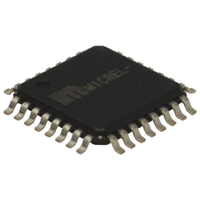
| 产品图片 |
|
| rohs | 符合RoHS无铅 / 符合限制有害物质指令(RoHS)规范要求 |
| 产品系列 | 时钟和计时器IC,延迟线/计时元素,Maxim Integrated DS1100LZ-50+- |
| 数据手册 | |
| 产品型号 | DS1100LZ-50+ |
| 产品培训模块 | http://www.digikey.cn/PTM/IndividualPTM.page?site=cn&lang=zhs&ptm=25703http://www.digikey.cn/PTM/IndividualPTM.page?site=cn&lang=zhs&ptm=25705 |
| 产品目录页面 | |
| 产品种类 | 延迟线/计时元素 |
| 传播延迟时间 | 50 ns |
| 低电平输出电流 | 8 mA |
| 供应商器件封装 | 8-SOIC N |
| 其它名称 | DS1100LZ50 |
| 功能 | 不可编程 |
| 包装 | 管件 |
| 可用总延迟 | 50ns |
| 商标 | Maxim Integrated |
| 安装类型 | 表面贴装 |
| 安装风格 | SMD/SMT |
| 封装 | Tube |
| 封装/外壳 | 8-SOIC(0.154",3.90mm 宽) |
| 封装/箱体 | SOIC-8 |
| 工作温度 | -40°C ~ 85°C |
| 工作温度范围 | - 40 C to + 85 C |
| 工厂包装数量 | 100 |
| 延迟到第一抽头 | 10ns |
| 抽头/步数 | 5 |
| 抽头增量 | 10ns |
| 最大工作温度 | + 85 C |
| 最小工作温度 | - 40 C |
| 标准包装 | 1 |
| 独立延迟数 | 1 |
| 电压-电源 | 3 V ~ 3.6 V |
| 电源电压-最大 | 3.6 V |
| 电源电压-最小 | 3 V |
| 电源电流 | 10 mA |
| 系列 | DS1100LZ |
| 逻辑系列 | DS1100L |
| 零件号别名 | 90-1100Z+L50 DS1100LZ |
| 高电平输出电流 | -1 mA |


PDF Datasheet 数据手册内容提取
DS1100L 3.3V 5-Tap Economy Timing Element (Delay Line) GENERAL DESCRIPTION FEATURES The DS1100L is a 3.3V version of the DS1100. It All-Silicon Timing Circuit is characterized for operation over the range 3.0V Five Taps Equally Spaced to 3.6V. The DS1100L series delay lines have Delays are Stable and Precise five equally spaced taps providing delays from Both Leading- and Trailing-Edge Accuracy 4ns to 500ns. These devices are offered in 3.3V Version of the DS1100 surface-mount packages to save PCB area. Low Low-Power CMOS cost and superior reliability over hybrid TTL-/CMOS-Compatible technology is achieved by the combination of a Vapor-Phase and IR Solderable 100% silicon delay line and industry-standard Custom Delays Available µMAX® and SO packaging. The DS1100L 5-tap Fast-Turn Prototypes silicon delay line reproduces the input-logic state Delays Specified Over Both Commercial and at the output after a fixed delay as specified by Industrial Temperature Ranges the extension of the part number after the dash. The DS1100L is designed to reproduce both PIN ASSIGNMENT leading and trailing edges with equal precision. Each tap is capable of driving up to 10 74LS IN 1 8 VCC loads. TAP 2 2 7 TAP 1 Maxim Integrated can customize standard DS1100L products to meet special needs. TAP 4 3 6 TAP 3 GND 4 5 TAP 5 µMAX is a registered trademark of Maxim Integrated Products, Inc. DS1100LZ SO (150mils) DS1100LU µMAX PIN DESCRIPTION TAP 1 to TAP 5 - TAP Output Number V - +3.3V CC GND - Ground IN - Input 19-5736; Rev 7/15 1 of 7
DS1100L ABSOLUTE MAXIMUM RATINGS Voltage Range on Any Pin Relative to Ground ........................................... -0.5V to +6.0V Short-Circuit Output Current ............................................................................ 50mA for 1s Continuous Power Dissipation (T = +70°C) A SO (derate 5.9mW/°C above +70°C) ................................................................ 470.6mW µMAX (derate 4.5mW/°C above +70°C .............................................................. 362mW Operating Temperature Range .................................................................... -40°C to +85°C Storage Temperature Range ...................................................................... -55°C to +125°C Lead Temperature (soldering, 10s)........................................................................... +300°C Soldering Temperature (reflow) Lead(Pb)-free ........................................................................................................ +260°C Containing lead(Pb) ............................................................................................... +240°C This is a stress rating only and functional operation of the device at these or any other conditions above those indicated in the operation sections of this specification is not implied. Exposure to absolute maximum rating conditions for extended periods of time may affect device reliability. DC ELECTRICAL CHARACTERISTICS (V = 3.0V to 3.6V; T = -40°C to +85°C, unless otherwise noted.) CC A PARAMETER SYMBOL CONDITIONS MIN TYP MAX UNITS NOTES Supply Voltage V 3.0 3.3 3.6 V 5 CC High-Level V + V 2.0 CC V 5 Input Voltage IH 0.3 Low-Level V -0.3 0.8 V 5 Input Voltage IL Input-Leakage I 0.0V ≤ V ≤ V -1.0 +1.0 μA Current I I CC Active Current I V = Max; Freq. = 1MHz 10 mA 6, 8 CC CC High-Level I V = Min. V = 2.3 -1 mA Output Current OH CC OH Low-Level I V = Min. V = 0.5 8 mA Output Current OL CC OL AC ELECTRICAL CHARACTERISTICS (V = 3.0V to 3.6V; T = -40°C to +85°C, unless otherwise noted.) CC A PARAMETER SYMBOL CONDITIONS MIN TYP MAX UNITS NOTES 20% of Input t Tap 5 ns 9 Pulse Width WI t PLH 1, 3, 4, +25°C 3.3V -2 Table 1 +2 ns 7, 10 Input-to-Tap t 1, 2, 3, Delay Tolerance PLH, 0°C to +70°C -3 Table 1 +3 ns t 4, 7, 10 (Delays ≤ 40ns) PHL 1, 2, 3, -40°C to +85°C -4 Table 1 +4 ns 4, 7, 10 1, 3, 4, +25°C 3.3V -5 Table 1 +5 % 7, 10 Input-to-Tap t 1, 2, 3, Delay Tolerance PLH, 0°C to +70°C -8 Table 1 +8 % t 4, 7, 10 (Delays > 40ns) PHL 1, 2, 3, -40°C to +85°C -13 Table 1 +13 % 4, 7, 10 Output Rise or Fall t , t 2.0 2.5 ns Time OF OR Power-Up Time t 200 μs PU Input Period Period 2(t ) ns 9 WI 2 of 7
DS1100L CAPACITANCE (T = +25°C, unless otherwise noted.) A PARAMETER SYMBOL CONDITIONS MIN TYP MAX UNITS NOTES Input Capacitance C 5 10 pF IN NOTES: 1) Initial tolerances are ± with respect to the nominal value at +25°C and V = 3.3V for both leading and CC trailing edge. 2) Temperature and voltage tolerance is with respect to the nominal delay value over the stated temperature range, and a supply-voltage range of 3.0V to 3.6V. 3) All tap delays tend to vary unidirectionally with temperature or voltage changes. For example, if TAP 1 slows down, all other taps also slow down; TAP 3 can never be faster than TAP 2. 4) Intermediate delay values are available on a custom basis. For further information, contact the factory at custom.oscillators@maximintegrated.com. 5) All voltages are referenced to ground. 6) Measured with outputs open. 7) See Test Conditions section at the end of this data sheet. 8) Frequencies higher than 1MHz result in higher I values. CC 9) At or near maximum frequency the delay accuracy can vary and will be application sensitive (i.e., decoupling, layout). 10) The “-75” version is specified and tested with an additional 2ns of tolerance on the specified minimum input-to-tap delay tolerance parameters for TAP 1 to TAP 3. Delay values for TAP 4 to TAP 5 meet data sheet specifications. Figure 1. LOGIC DIAGRAM Figure 2. TIMING DIAGRAM: SILICON DELAY LINE 3 of 7
DS1100L TERMINOLOGY Period: The time elapsed between the leading edge of the first pulse and the leading edge of the following pulse. t (Pulse Width): The elapsed time on the pulse between the 1.5V point on the leading edge and the WI 1.5V point on the trailing edge or the 1.5V point on the trailing edge and the 1.5V point on the leading edge. t (Input Rise Time): The elapsed time between the 20% and the 80% point on the leading edge of the RISE input pulse. t (Input Fall Time): The elapsed time between the 80% and the 20% point on the trailing edge of the FALL input pulse. t (Time Delay, Rising): The elapsed time between the 1.5V point on the leading edge of the input PLH pulse and the 1.5V point on the leading edge of any tap output pulse. t (Time Delay, Falling): The elapsed time between the 1.5V point on the trailing edge of the input PHL pulse and the 1.5V point on the trailing edge of any tap output pulse. TEST SETUP DESCRIPTION Figure 3 illustrates the hardware configuration used for measuring the timing parameters on the DS1100L. The input waveform is produced by a precision pulse generator under software control. Time delays are measured by a time interval counter (20ps resolution) connected between the input and each tap. Each tap is selected and connected to the counter by a VHF switch control unit. All measurements are fully automated, with each instrument controlled by a central computer over an IEEE 488 bus. TEST CONDITIONS INPUT: Ambient Temperature: 25°C ±3°C Supply Voltage (V ): 3.3V ±0.1V CC Input Pulse: High = 3.0V ±0.1V Low = 0.0V ±0.1V Source Impedance: 50Ω max Rise and Fall Time: 3.0ns max (measured between 10% and 90%) Pulse Width: 500ns (1μs for -500 version) Period: 1μs (2μs for -500 version) OUTPUT: Each output is loaded with the equivalent of one 74F04 input gate. Delay is measured at the 1.5V level on the rising and falling edge. Note: Above conditions are for test only and do not restrict the operation of the device under other data sheet conditions. 4 of 7
DS1100L Figure 3. TEST CIRCUIT Table 1. DS1100L PART NUMBER DELAY PART NOMINAL DELAYS (ns) DS1100L-xxx TAP 1 TAP 2 TAP 3 TAP 4 TAP 5 -20 4 8 12 16 20 -25 5 10 15 20 25 -30 6 12 18 24 30 -35 7 14 21 28 35 -40 8 16 24 32 40 -45 9 18 27 36 45 -50 10 20 30 40 50 -60 12 24 36 48 60 -75 15 30 45 60 75 -100 20 40 60 80 100 -125 25 50 75 100 125 -150 30 60 90 120 150 -175 35 70 105 140 175 -200 40 80 120 160 200 -250 50 100 150 200 250 -300 60 120 180 240 300 -500 100 200 300 400 500 5 of 7
DS1100L ORDERING INFORMATION PART TEMP RANGE PIN-PACKAGE DS1100LZ-xxx -40°C to +85°C 8 SO DS1100LZ-xxx/T&R -40°C to +85°C 8 SO DS1100LZ-xxx+ -40°C to +85°C 8 SO DS1100LZ-xxx+T -40°C to +85°C 8 SO DS1100LU-xxx -40°C to +85°C 8 µMAX DS1100LU-xxx/T&R -40°C to +85°C 8 µMAX DS1100LU-xxx+ -40°C to +85°C 8 µMAX DS1100LU-xxx+T -40°C to +85°C 8 µMAX xxx Denotes total time delay (ns) (see Table 1). +Denotes a lead(Pb)-free/RoHS-compliant package. T&R and T = Tape and reel. PACKAGE INFORMATION For the latest package outline information and land patterns (footprints), go to www.maximintegrated.com/packages. Note that a “+”, “#”, or “-” in the package code indicates RoHS status only. Package drawings may show a different suffix character, but the drawing pertains to the package regardless of RoHS status. PACKAGE TYPE PACKAGE CODE OUTLINE NO. LAND PATTERN NO. 8 SO (150 mils) S8+4 21-0041 90-0096 8 µMAX U8+1 21-0036 90-0092 6 of 7
DS1100L REVISION HISTORY REVISION PAGES DESCRIPTION DATE CHANGED Changed µSOP package type to µMAX; updated the Absolute Maximum Ratings section; added the customer support email address to 3/11 1−6 the electrical characteristics Note 4; added the Ordering Information and Package Information tables Added continuous power dissipation numbers to the Absolute Maximum Ratings section; added Note 10 to the Input-to-Tap Delay 10/11 2, 3 Tolerance (Delays ≤ 40ns) parameter in the AC Electrical Characteristics table 7/15 Revised Note 10 and revised AC Electrical Characteristics table 2, 3 7 of 7 Maxim Integrated cannot assume responsibility for use of any circuitry other than circuitry entirely embodied in a Maxim Integrated product. No circuit patent licenses are implied. Maxim Integrated reserves the right to change the circuitry and specifications without notice at any time. The parametric values (min and max limits) shown in the Electrical Characteristics table are guaranteed. Other parametric values quoted in this data sheet are provided for guidance. Maxim Integrated 160 Rio Robles, San Jose, CA 95134 USA 1-408-601-1000 © 2015 Maxim Integrated Products, Inc. Maxim Integrated and the Maxim Integrated logo are trademarks of Maxim Integrated Products, Inc.