ICGOO在线商城 > 电感器,线圈,扼流圈 > 阵列,信号变压器 > DRQ73-150-R
 Datasheet下载
- 型号: DRQ73-150-R
- 制造商: Bussmann/Cooper
- 库位|库存: xxxx|xxxx
- 要求:
| 数量阶梯 | 香港交货 | 国内含税 |
| +xxxx | $xxxx | ¥xxxx |
查看当月历史价格
查看今年历史价格
DRQ73-150-R产品简介:
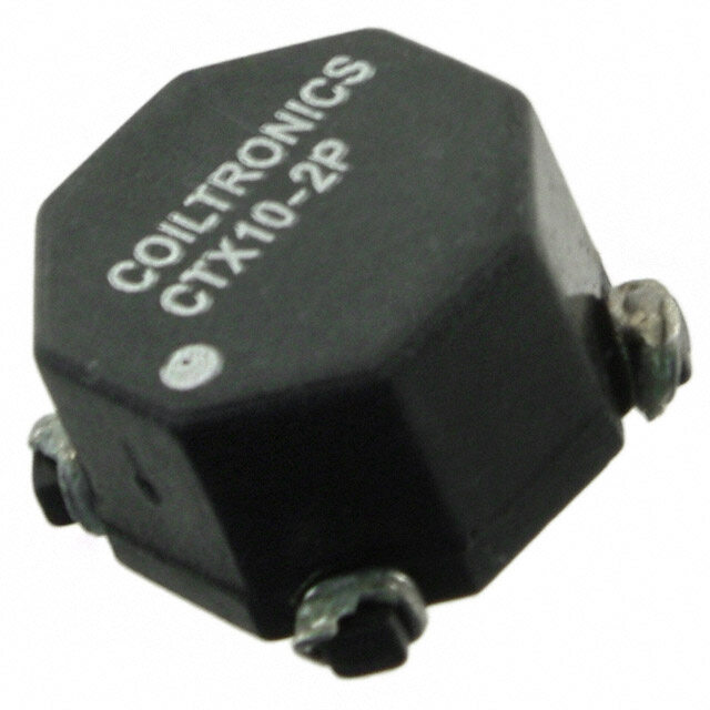
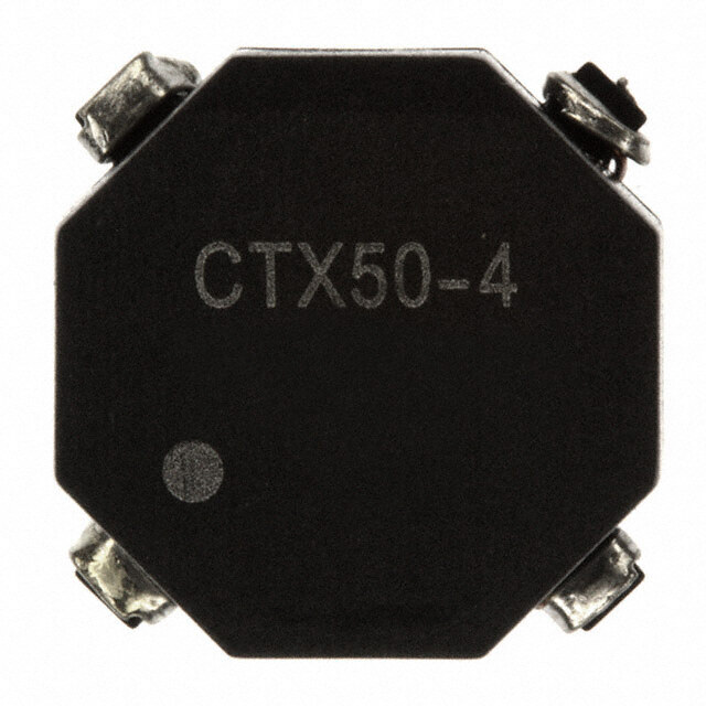
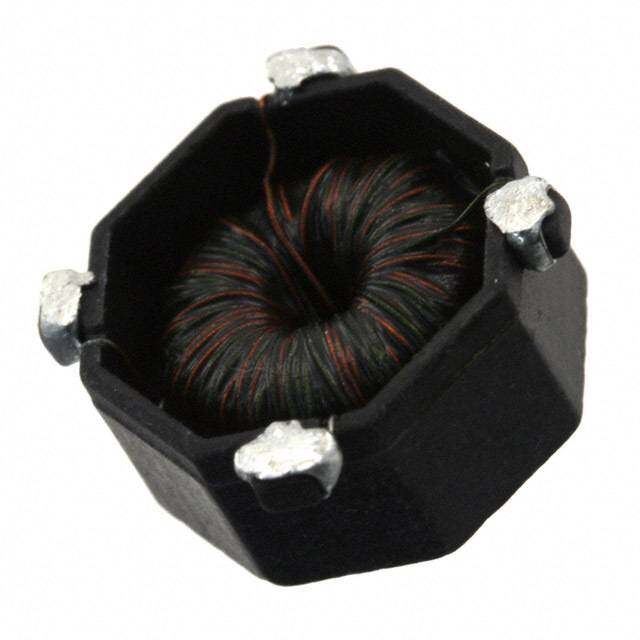
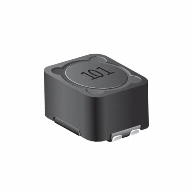
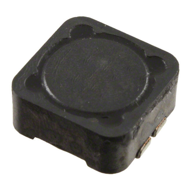
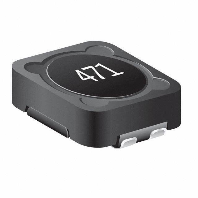
ICGOO电子元器件商城为您提供DRQ73-150-R由Bussmann/Cooper设计生产,在icgoo商城现货销售,并且可以通过原厂、代理商等渠道进行代购。 DRQ73-150-R价格参考¥4.96-¥5.68。Bussmann/CooperDRQ73-150-R封装/规格:阵列,信号变压器, Shielded 2 Coil Inductor Array 60.04µH Inductance - Connected in Series 15.01µH Inductance - Connected in Parallel 84.4 mOhm DC Resistance (DCR) - Parallel 1.83A Nonstandard。您可以下载DRQ73-150-R参考资料、Datasheet数据手册功能说明书,资料中有DRQ73-150-R 详细功能的应用电路图电压和使用方法及教程。
Eaton品牌的DRQ73-150-R型号信号变压器属于阵列类别,主要用于工业控制、通信系统和电力自动化设备中。以下是其典型应用场景:

1. 信号隔离与传输:
   该型号的信号变压器用于实现输入和输出信号之间的电气隔离,防止干扰并确保信号的稳定传输。适用于需要高可靠性和低噪声的场景,例如数据采集系统和传感器接口。

2. 工业自动化控制:
   在PLC(可编程逻辑控制器)、DCS(分布式控制系统)和其他工业自动化设备中,DRQ73-150-R可用于信号调理和转换,确保控制系统中的信号准确无误地传递。

3. 通信设备:
   该变压器适用于通信网络中的信号耦合与隔离,例如以太网供电(PoE)设备、调制解调器和路由器等,保障数据传输的稳定性和安全性。

4. 电力监控系统:
   在电力监测和保护装置中,DRQ73-150-R可用于电流或电压信号的隔离放大,帮助实现对电网参数的精确测量和分析。

5. 医疗设备:
   对于需要严格电气隔离的医疗仪器(如监护仪、超声设备),该型号的信号变压器可以提供可靠的信号处理能力,同时满足安全标准。

6. 新能源领域:
   在太阳能逆变器、风能控制器等新能源设备中,DRQ73-150-R可用于信号反馈和隔离,确保系统的高效运行和稳定性。

总结来说,Eaton DRQ73-150-R信号变压器以其高可靠性、低损耗和良好的电磁兼容性,广泛应用于需要信号隔离、传输和转换的各种工业和商业场景中。
| 参数 | 数值 |
| 产品目录 | |
| DC电阻(DCR) | 169.5 毫欧 |
| 描述 | INDUCT ARRAY 2 COIL 15.01UH SMD固定电感器 15uH 2.05A 0.0844ohms |
| 产品分类 | |
| 品牌 | Eaton Bussmann |
| 产品手册 | |
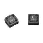
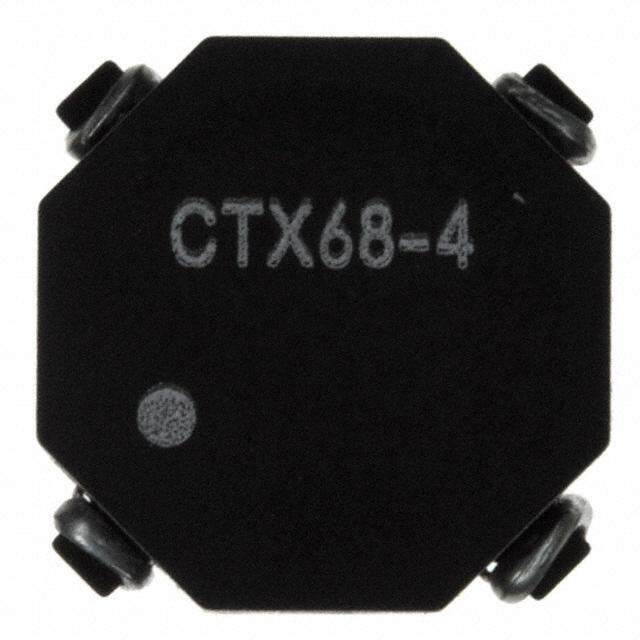
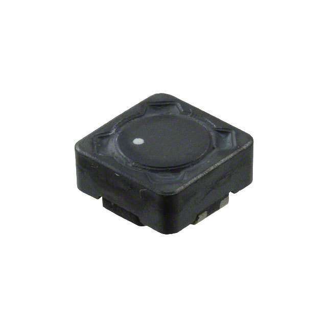
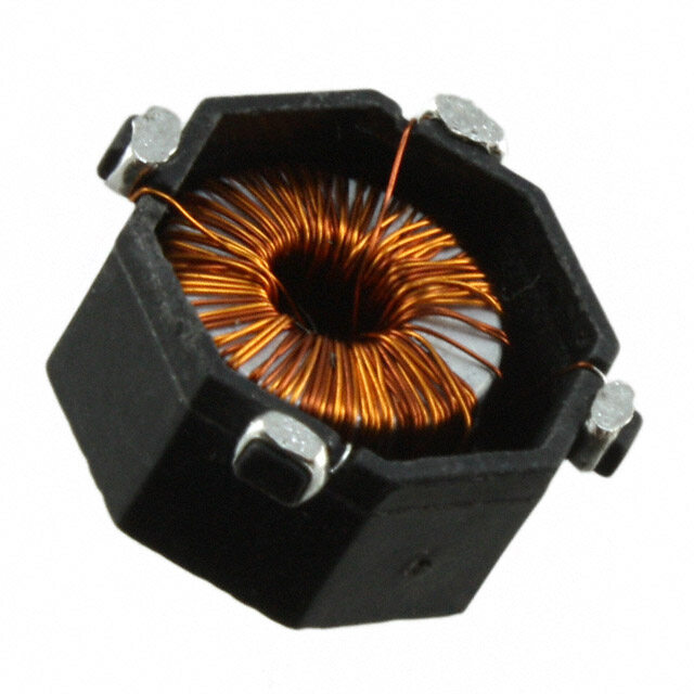
| 产品图片 |
|
| rohs | 符合RoHS无铅 / 符合限制有害物质指令(RoHS)规范要求 |
| 产品系列 | 固定电感器,Coiltronics / Eaton DRQ73-150-RDRQ |
| 数据手册 | |
| 产品型号 | DRQ73-150-R |
| 产品 | Inductors |
| 产品培训模块 | http://www.digikey.cn/PTM/IndividualPTM.page?site=cn&lang=zhs&ptm=25759http://www.digikey.cn/PTM/IndividualPTM.page?site=cn&lang=zhs&ptm=26315 |
| 产品目录绘图 |
|
| 产品目录页面 | |
| 产品种类 | 固定电感器 |
| 其它名称 | 513-1245-6 |
| 包装 | Digi-Reel® |
| 单位重量 | 1 g |
| 商标 | Coiltronics / Eaton |
| 外壳宽度 | 7.6 mm |
| 外壳长度 | 7.6 mm |
| 外壳高度 | 3.55 mm |
| 大小/尺寸 | 0.299" 长 x 0.299" 宽(7.60mm x 7.60mm) |
| 安装类型 | 表面贴装 |
| 容差 | ±20% |
| 封装 | Reel |
| 封装/外壳 | 非标准 |
| 屏蔽 | 屏蔽 |
| 工作温度范围 | - 40 C to + 125 C |
| 工厂包装数量 | 1350 |
| 最大直流电流 | 2.05 A |
| 最大直流电阻 | 84.4 mOhms |
| 标准包装 | 1 |
| 测试频率 | 100 kHz |
| 电感 | 15 uH |
| 电感-串联连接 | 60.04µH |
| 电感-并联连接 | 15.01µH |
| 电流 | 916mA |
| 端接类型 | SMD/SMT |
| 类型 | Dual Winding Inductor |
| 系列 | DRQ73 |
| 线圈数 | 2 |
| 芯体材料 | Ferrite |
| 高度 | 0.140"(3.55mm) |


- 商务部:美国ITC正式对集成电路等产品启动337调查
- 曝三星4nm工艺存在良率问题 高通将骁龙8 Gen1或转产台积电
- 太阳诱电将投资9.5亿元在常州建新厂生产MLCC 预计2023年完工
- 英特尔发布欧洲新工厂建设计划 深化IDM 2.0 战略
- 台积电先进制程称霸业界 有大客户加持明年业绩稳了
- 达到5530亿美元!SIA预计今年全球半导体销售额将创下新高
- 英特尔拟将自动驾驶子公司Mobileye上市 估值或超500亿美元
- 三星加码芯片和SET,合并消费电子和移动部门,撤换高东真等 CEO
- 三星电子宣布重大人事变动 还合并消费电子和移动部门
- 海关总署:前11个月进口集成电路产品价值2.52万亿元 增长14.8%
PDF Datasheet 数据手册内容提取
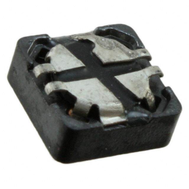
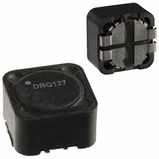
Effective September 2017 Technical Data DS4311 Supersedes April 2014 DRQ Dual winding, high power density, shielded drum core power inductors Applications • Desktop and servers • DVD and media players • Portable and handheld devices • LCD panels • As a transformer: SEPIC, flyback • As an inductor: buck, boost, coupled inductor • DC-DC Converters • VRM inductor for CPU and DDR power supplies • Input and output filter chokes Environmental data Product features • Dual winding inductors that can be used as • Storage temperature range (component): either a single inductor, or in coupled -40 °C to +125 °C inductor/transformer applications • Operating temperature range: -40 °C to +125 °C (1:1 turns ratio) (ambient plus self-temperature rise) • Four sizes of shielded drum core inductors • Solder reflow temperature: • Windings can be connected in series or J-STD-020 (latest revision) compliant parallel, offering a broad range of inductance and current ratings Pb HHALOFGEN • Peak current ratings from 0.13 A to 56 A FREE • RMS current ratings from 0.128 A to 17.9 A • Inductance ratings from 0.33 µH to 4.02 mH • 200 Vac Isolation between windings • Ferrite core material
DRQ Technical Data DS4311 Effective September 2017 Dual winding, high power density, shielded drum core power inductors Product specifications Parallel Ratings Series Ratings Rated OCL1 I 3 OCL1 I 3 sat sat Inductance ±20% I 2 (A) DCR Ω4 Volt5 ±20% I 2 (A) DCR Ω4 Volt5 rms rms Part Number (µH) (µH) (A) Peak typ. µ-sec (µH) (A) Peak typ. µ-sec DRQ73-R33-R 0.33 0.306 6.19 14.4 0.0074 1.98 1.224 3.10 7.18 0.0296 3.96 DRQ73-1R0-R 1.00 0.992 5.25 7.97 0.0103 3.56 3.968 2.63 3.99 0.0411 7.12 DRQ73-1R5-R 1.50 1.482 4.64 6.52 0.0132 4.36 5.928 2.32 3.26 0.0527 8.72 DRQ73-2R2-R 2.20 2.070 4.11 5.52 0.0167 5.15 8.280 2.06 2.76 0.0669 10.3 DRQ73-3R3-R 3.30 3.540 3.31 4.22 0.0259 6.73 14.16 1.66 2.11 0.1035 13.5 DRQ73-4R7-R 4.70 4.422 3.09 3.78 0.0297 7.52 17.69 1.55 1.89 0.1188 15.0 DRQ73-6R8-R 6.80 6.480 2.55 3.12 0.0435 9.11 25.92 1.28 1.56 0.1742 18.2 DRQ73-8R2-R 8.20 8.930 2.19 2.66 0.0592 10.7 35.72 1.10 1.33 0.2368 21.4 DRQ73-100-R 10.0 10.30 2.08 2.47 0.0656 11.5 41.20 1.04 1.24 0.2623 23.0 DRQ73-150-R 15.0 15.01 1.83 2.05 0.0844 13.9 60.04 0.916 1.03 0.339 27.8 DRQ73-220-R 22.0 22.65 1.62 1.67 0.107 17.0 90.60 0.811 0.83 0.429 34.0 DRQ73-330-R 33.0 34.41 1.31 1.35 0.166 21.0 137.6 0.653 0.68 0.665 42.0 DRQ73-470-R 47.0 48.62 1.08 1.14 0.241 24.9 194.5 0.542 0.57 0.965 49.8 DRQ73-680-R 68.0 68.91 0.89 0.96 0.358 29.7 275.6 0.444 0.48 1.43 59.4 DRQ73-820-R 82.0 80.37 0.86 0.89 0.384 32.1 321.5 0.430 0.44 1.54 64.2 DRQ73-101-R 100 101.4 0.73 0.79 0.527 36.0 405.6 0.367 0.39 2.11 72.0 DRQ73-151-R 150 150.9 0.58 0.65 0.851 44.0 603.6 0.289 0.32 3.41 88.0 DRQ73-221-R 220 223.3 0.52 0.53 1.05 53.5 893.2 0.260 0.27 4.20 107 DRQ73-331-R 330 325.5 0.42 0.44 1.59 64.5 1302 0.211 0.22 6.36 129 DRQ73-471-R 470 465.8 0.35 0.37 2.36 77.2 1863 0.173 0.18 9.44 154 DRQ73-681-R 680 676.5 0.29 0.31 3.47 93.1 2706 0.143 0.15 13.88 186 DRQ73-821-R 820 821.7 0.27 0.28 3.93 103 3287 0.134 0.14 15.72 206 DRQ73-102-R 1000 995.0 0.26 0.25 4.34 113 3980 0.128 0.13 17.36 226 1. Open Circuit Inductance Test Parameters: 100 kHz, 0.25 V , 0.0 Adc 6. Turns Ratio (1:3):(2-4) 1:1 rms Parallel: (1,2 -4,3) Series: (1-4) tie (2-3) 7. Part number definition: DRQxxx-yyy- 2. RMS current for an approximate DT of 40 °C without core loss. - DRQxxx = product code and size, It is recommended that the temperature of the part not exceed +125 °C. - yyy = inductance value in µH, 3. Peak current for approximately 30% roll-off at +20 °C - R = decimal point. If no R is present, third character = # of zeros 4. DCR limits @ +20 °C - “-R” suffix = RoHS complian 5. Applied Volt-Time product (V-µs) across the inductor. This value represents the applied V-µs at 100 kHz necessary to generate a core loss equal to 10% of the total losses for a 40 °C temperature rise. 2 www.eaton.com/electronics
DRQ Technical Data DS4311 Dual winding, high power density, shielded drum core power inductors Effective September 2017 Product specifications Parallel Ratings Series Ratings Rated OCL1 I 3 OCL1 I 3 sat sat Inductance ±20% I 2 (A) DCR Ω4 Volt5 ±20% I 2 (A) DCR Ω4 Volt5 rms rms Part Number (µH) (µH) (A) Peak Typ. µ-sec (µH) (A) Peak Typ. µ-sec DRQ74-R33-R 0.33 0.294 6.20 18.4 0.0074 1.71 1.176 3.10 9.18 0.0295 3.42 DRQ74-1R0-R 1.00 0.952 5.33 10.2 0.0100 3.08 3.808 2.66 5.10 0.0400 6.16 DRQ74-1R5-R 1.50 1.422 4.96 8.35 0.0115 3.76 5.688 2.48 4.17 0.0461 7.52 DRQ74-2R2-R 2.20 1.986 4.66 7.06 0.0130 4.45 7.944 2.33 3.53 0.0521 8.9 DRQ74-3R3-R 3.30 3.396 3.94 5.40 0.0183 5.81 13.58 1.97 2.70 0.0732 11.6 DRQ74-4R7-R 4.70 5.182 3.34 4.37 0.0254 7.18 20.73 1.67 2.19 0.102 14.4 DRQ74-6R8-R 6.80 7.344 2.60 3.67 0.0418 8.55 29.38 1.30 1.84 0.167 17.1 DRQ74-8R2-R 8.20 8.566 2.53 3.40 0.0441 9.23 34.26 1.27 1.70 0.177 18.5 DRQ74-100-R 10.0 9.882 2.41 3.17 0.0489 9.92 39.53 1.20 1.58 0.196 19.8 DRQ74-150-R 15.0 16.09 2.11 2.48 0.0637 12.7 64.36 1.05 1.24 0.255 25.4 DRQ74-220-R 22.0 21.73 1.75 2.13 0.0925 14.7 86.92 0.874 1.07 0.371 29.4 DRQ74-330-R 33.0 33.01 1.41 1.73 0.143 18.1 132.0 0.702 0.87 0.574 36.2 DRQ74-470-R 47.0 49.64 1.15 1.41 0.216 22.2 198.6 0.573 0.71 0.865 44.4 DRQ74-680-R 68.0 69.67 1.03 1.19 0.265 26.3 278.7 0.517 0.60 1.06 52.6 DRQ74-820-R 82.0 80.95 0.91 1.11 0.345 28.4 323.8 0.453 0.55 1.38 56.8 DRQ74-101-R 100 101.6 0.86 0.99 0.383 31.8 406.4 0.430 0.49 1.53 63.6 DRQ74-151-R 150 150.0 0.69 0.81 0.591 38.6 600.0 0.346 0.41 2.37 77.2 DRQ74-221-R 220 227.0 0.56 0.66 0.907 47.5 908.0 0.279 0.33 3.63 95 DRQ74-331-R 330 335.6 0.45 0.54 1.41 57.8 1342 0.224 0.27 5.66 116 DRQ74-471-R 470 465.3 0.40 0.46 1.74 68.1 1861 0.202 0.23 6.97 136 DRQ74-681-R 680 671.2 0.33 0.38 2.58 81.7 2685 0.166 0.19 10.3 163 DRQ74-821-R 820 812.7 0.31 0.35 2.93 89.9 3251 0.156 0.17 11.7 180 DRQ74-102-R 1000 1009 0.27 0.31 3.89 100 4036 0.135 0.16 15.6 200 1. Open Circuit Inductance Test Parameters: 100 kHz, 0.25 V , 0.0 Adc 6. Turns Ratio (1:3):(2-4) 1:1 rms Parallel: (1,2 -4,3) Series: (1-4) tie (2-3) 7. Part number definition: DRQxxx-yyy- 2. RMS current for an approximate DT of 40 °C without core loss. - DRQxxx = product code and size, It is recommended that the temperature of the part not exceed +125 °C. - yyy = inductance value in µH, 3. Peak current for approximately 30% roll-off at +20 °C - R = decimal point. If no R is present, third character = # of zeros 4. DCR limits @ +20 °C - “-R” suffix = RoHS complian 5. Applied Volt-Time product (V-µs) across the inductor. This value represents the applied V-µs at 100 kHz necessary to generate a core loss equal to 10% of the total losses for a 40 °C temperature rise. www.eaton.com/electronics 3
Technical Data DS4311 DRQ Effective September 2017 Dual winding, high power density, shielded drum core power inductors Product specifications Parallel Ratings Series Ratings Rated OCL1 I 3 OCL1 I 3 Inductance sat sat ±20% I 2 (A) DCR Ω4 Volt5 ±20% I 2 (A) DCR Ω4 Volt5 rms rms Part Number (µH) (µH) (A) Peak typ. µ-sec (µH) (A) Peak typ. µ-sec DRQ125-R47-R 0.47 0.456 17.6 33.0 0.0018 3.17 1.824 8.80 16.5 0.0078 6.34 DRQ125-1R0-R 1.00 0.894 15.0 23.6 0.0024 4.43 3.576 7.51 11.8 0.0096 8.86 DRQ125-1R5-R 1.50 1.478 13.8 18.3 0.0029 5.70 5.912 6.89 9.15 0.0114 11.40 DRQ125-2R2-R 2.20 2.208 10.9 15.0 0.0045 6.97 8.832 5.46 7.50 0.0182 13.9 DRQ125-3R3-R 3.30 3.084 9.26 12.7 0.0063 8.23 12.34 4.63 6.35 0.0253 16.5 DRQ125-4R7-R 4.70 5.274 7.18 9.71 0.0105 10.8 21.10 3.59 4.86 0.0420 21.6 DRQ125-6R8-R 6.80 6.588 6.64 8.68 0.0123 12.0 26.35 3.32 4.34 0.0492 24.0 DRQ125-8R2-R 8.20 8.048 5.54 7.86 0.0176 13.3 32.19 2.77 3.93 0.0705 26.6 DRQ125-100-R 10.0 9.654 5.35 7.17 0.0189 14.6 38.62 2.67 3.59 0.0757 29.2 DRQ125-150-R 15.0 15.35 4.27 5.69 0.0298 18.4 61.40 2.13 2.85 0.120 36.8 DRQ125-220-R 22.0 22.36 3.70 4.71 0.0396 22.2 89.44 1.84 2.36 0.159 44.4 DRQ125-330-R 33.0 33.74 3.28 3.84 0.0505 27.2 135.0 1.64 1.92 0.203 54.4 DRQ125-470-R 47.0 47.47 2.71 3.24 0.0740 32.3 189.9 1.35 1.62 0.297 64.6 DRQ125-680-R 68.0 67.91 2.22 2.70 0.101 38.6 271.6 1.11 1.35 0.440 77.2 DRQ125-820-R 82.0 86.89 2.05 2.39 0.128 43.7 347.6 1.03 1.20 0.515 87.4 DRQ125-101-R 100 102.7 1.78 2.20 0.170 47.5 410.8 0.892 1.10 0.682 95.0 DRQ125-151-R 150 151.1 1.48 1.81 0.248 57.6 604.4 0.739 0.905 0.991 115.2 DRQ125-221-R 220 216.8 1.19 1.51 0.384 69.0 867.2 0.594 0.755 1.54 138 DRQ125-331-R 330 332.6 1.06 1.22 0.482 85.5 1330 0.530 0.610 1.93 171 DRQ125-471-R 470 473.1 0.87 1.02 0.718 102 1892 0.434 0.510 2.87 204 DRQ125-681-R 680 679.8 0.70 0.85 1.10 122 2719 0.350 0.425 4.42 244 DRQ125-821-R 820 828.0 0.60 0.77 1.49 135 3312 0.301 0.385 5.96 270 DRQ125-102-R 1000 1008 0.57 0.70 1.69 149 4032 0.283 0.350 6.76 298 1. Open Circuit Inductance Test Parameters: 100 kHz, 0.25 V , 0.0 Adc 6. Turns Ratio (1:3):(2-4) 1:1 rms Parallel: (1,2 -4,3) Series: (1-4) tie (2-3) 7. Part number definition: DRQxxx-yyy- 2. RMS current for an approximate DT of 40 °C without core loss. - DRQxxx = product code and size, It is recommended that the temperature of the part not exceed +125 °C. - yyy = inductance value in µH, 3. Peak current for approximately 30% roll-off at +20 °C - R = decimal point. If no R is present, third character = # of zeros 4. DCR limits @ +20 °C - “-R” suffix = RoHS complian 5. Applied Volt-Time product (V-µs) across the inductor. This value represents the applied V-µs at 100 kHz necessary to generate a core loss equal to 10% of the total losses for a 40 °C temperature rise. 4 www.eaton.com/electronics
DRQ Technical Data DS4311 Dual winding, high power density, shielded drum core power inductors Effective September 2017 Product specifications Parallel Ratings Series Ratings Rated OCL1 I 3 OCL1 I 3 sat sat Inductance ±20% I 2 (A) DCR Ω4 Volt5 ±20% I 2 (A) DCR Ω4 Volt5 rms rms Part Number (µH) (µH) (A) Peak typ. µ-sec (µH) (A) Peak typ. µ-sec DRQ127-R47-R 0.47 0.419 17.9 56.0 0.00195 3.50 1.676 8.94 28 0.0078 7.00 DRQ127-1R0-R 1.00 0.821 15.5 40.0 0.00261 4.90 3.284 7.74 20 0.0104 9.80 DRQ127-1R5-R 1.50 1.357 13.5 31.1 0.00341 6.30 5.428 6.77 15.6 0.0137 12.60 DRQ127-2R2-R 2.20 2.027 12.5 25.5 0.00373 7.70 8.108 6.23 12.7 0.0161 15.4 DRQ127-3R3-R 3.30 2.831 10.4 21.5 0.00567 9.10 11.32 5.23 10.8 0.0229 18.2 DRQ127-4R7-R 4.70 4.841 8.25 16.5 0.00917 11.9 19.36 4.13 8.24 0.0367 23.8 DRQ127-6R8-R 6.80 7.387 7.34 13.3 0.0116 14.7 29.55 3.67 6.67 0.0465 29.4 DRQ127-8R2-R 8.20 8.861 6.32 12.2 0.0157 16.1 35.44 3.16 6.09 0.0627 32.2 DRQ127-100-R 10.0 10.47 6.04 11.2 0.0172 17.5 41.88 3.02 5.60 0.0686 35.0 DRQ127-150-R 15.0 14.09 5.03 9.66 0.0247 20.3 56.36 2.51 4.83 0.0990 40.6 DRQ127-220-R 22.0 22.93 4.00 7.57 0.0391 25.9 91.72 2.00 3.78 0.157 51.8 DRQ127-330-R 33.0 33.92 3.23 6.22 0.0600 31.5 135.7 1.61 3.11 0.241 63.0 DRQ127-470-R 47.0 47.05 2.95 5.28 0.0719 37.1 188.2 1.47 2.64 0.288 74.2 DRQ127-680-R 68.0 66.48 2.44 4.44 0.105 44.1 265.9 1.22 2.22 0.421 88.2 DRQ127-820-R 82.0 79.75 2.09 4.06 0.143 48.3 319.0 1.04 2.03 0.573 96.6 DRQ127-101-R 100 99.31 1.96 3.64 0.163 53.9 397.2 0.980 1.82 0.653 107.8 DRQ127-151-R 150 144.9 1.59 3.01 0.247 65.1 579.6 0.796 1.51 0.989 130.2 DRQ127-221-R 220 221.5 1.29 2.43 0.376 80.5 886.0 0.645 1.22 1.50 161 DRQ127-331-R 330 323.6 1.04 2.01 0.574 97.3 1294 0.522 1.01 2.30 195 DRQ127-471-R 470 467.1 0.85 1.68 0.861 117 1868 0.427 0.838 3.44 234 DRQ127-681-R 680 676.7 0.76 1.39 1.08 141 2707 0.380 0.697 4.32 282 DRQ127-821-R 820 818.1 0.65 1.27 1.47 155 3272 0.325 0.633 5.88 310 DRQ127-102-R 1000 1005 0.61 1.14 1.66 172 4020 0.307 0.571 6.64 344 1. Open Circuit Inductance Test Parameters: 100 kHz, 0.25 V , 0.0 Adc 6. Turns Ratio (1:3):(2-4) 1:1 rms Parallel: (1,2 -4,3) Series: (1-4) tie (2-3) 7. Part number definition: DRQxxx-yyy- 2. RMS current for an approximate DT of 40 °C without core loss. - DRQxxx = product code and size, It is recommended that the temperature of the part not exceed +125 °C. - yyy = inductance value in µH, 3. Peak current for approximately 30% roll-off at 20°C - R = decimal point. If no R is present, third character = # of zeros 4. DCR limits @ +20 °C - “-R” suffix = RoHS complian 5. Applied Volt-Time product (V-µs) across the inductor. This value represents the applied V-µs at 100 kHz necessary to generate a core loss equal to 10% of the total losses for a 40 °C temperature rise. www.eaton.com/electronics 5
DRQ Technical Data DS4311 Effective September 2017 Dual winding, high power density, shielded drum core power inductors Dimensions - mm DRQ73 Recommended Pad Layout Side View Top View 3.55 Max 1.73 1.00 0.40 1.00 0.40 • DRQ73 ### 7.6 wllyy R Max. 1.73 7.9 7.9 Dual Inductor Mode Series Mode Bottom View Schematic 6.1 0.73 Dual Inductor Series Mode Parallel Mode 0.60 1 2 1 2 1 2 7.6 Max. L1 L2 L1 L2 L1 L2 0.80 3 4 3 4 3 4 DRQ74 Recommended Pad Layout Top View Side View 4.45 1.73 Max 1.00 0.40 1.00 0.40 • DRQ74 ### wllyy R 1.73 7.6 Max 7.9 7.9 Dual Inductor Mode Series Mode Bottom View Schematic 0.73 Dual Inductor Series Mode Parallel Mode 1 2 1 2 1 2 7.6 0.60 Max L1 L2 L1 L2 L1 L2 3 4 3 4 3 4 6.1 ### = Inductance value per family chart wllyy = Date code R = Revision level Dot indicates pin #1 Do not route traces or vias underneath the inductor 6 www.eaton.com/electronics
DRQ Technical Data DS4311 Dual winding, high power density, shielded drum core power inductors Effective September 2017 Dimensions - mm DRQ125 Side View Recommended Pad Layout Top View 6.00 Max 3.85 3.85 0.50 1 4 1 4 • 1 DRQ125 4 2.50 2.50 ### 2 3 2 3 12.5 2 wwllyy R 3 Max 0.50 13.80 13.80 Dual Inductor Mode Series Mode Bottom View 2.05 Schematic Dual Inductor Series Mode Parallel Mode 2.002 3 12.5 1 2 1 2 1 2 Max 1 4 L1 L2 L1 L2 L1 L2 3 4 3 4 3 4 10.0 DRQ127 Side View Recommended Pad Layout Top View 8.0 0.50 3.85 3.85 Max 1 4 1 •DRQ127 4 2.50 2.50 2 3 ### 12.5 2 wwllyy R 3 Max 0.50 13.80 13.80 Dual Inductor Mode Series Mode Bottom View 2.05 Schematic Dual Inductor Series Mode Parallel Mode 2.002 3 12.5 Max 1 2 1 2 1 2 1 4 L1 L2 L1 L2 L1 L2 10.0 3 4 3 4 3 4 ### = Inductance value per family chart wwllyy = (date code) R = revision level Dot indicates pin #1 Do not route traces or vias underneath the inductor www.eaton.com/electronics 7
Technical Data DS4311 DRQ Effective September 2017 Dual winding, high power density, shielded drum core power inductors Packaging information- mm DRQ73 Supplied in tape and reel packaging, 1350 parts per reel, 13" diameter reel. ACTUAL SIZE Ao=7.90mm DRQ73 Bo=7.90mm Ko=3.80mm Direction of Feed DRQ74 Supplied in tape and reel packaging, Ø1.50 +0.1/-0.0 1100 parts per reel, 13" diameter reel. 2.00 ±0.1 Ø1.50 Min. 4.00 A 1.75±0.10 2 1 7.50±0.1 16.00 BBo ###DRQ74 ±0.3 ACDTRUQAL7 4SIZE Ao=7.90mm 3 4 Bo=7.90mm Ko=4.70mm Ko A Ao 12.000 Direction of Feed SECTION A-A DRQ125 Supplied in tape and reel packaging, 4.0 600 parts per reel, 13" diameter reel. 1.5 dia +0.1/-0.0 2.0 1.5 dia min A 1.7 2 1 11.5 Ao=13.00mm BB0 wwllyy###DRQ125• +2/-40.0.3 ACDTRUQA1L2 S5IZE Bo=13.00mm 3 4 Ko=6.30mm K0 A Direction of Feed A0 16.00 SECTION A-A DRQ127 4.0 Supplied in tape and reel packaging, 1.5 dia 350 parts per reel, 13" diameter reel. +0.1/-0.0 2.0 1.5 dia min A 1.7 R0.3 max. 2 1 11..5 BB0 wwllyy###DRQ127 +2/-40.0.3 ACDTRUQA1L2 S7IZE Ao=13.00mm 3 4 Bo=13.00mm Direction of Feed Ko=8.30mm K0 A0 20.00 A SECTION A-A R0.5 TYP. Dimensions are in millimeters. 8 www.eaton.com/electronics
DRQ Technical Data DS4311 Dual winding, high power density, shielded drum core power inductors Effective September 2017 Core loss Irms Derating with Core Loss x) a m (s m Irm 300 KHz 200 KHz 100 KHz 50 KHz 25 KHz o s fr e s s o L of % % of Applied Volt-µsecond Inductance characteristics DRQ73 DRQ74 100 100 90 80 80 70 OCL (%) 6500 CL (%) 60 O 40 40 30 20 20 10 0 0 20 40 60 80 100 120 140 160 0 % of Isat 0 20 40 60 80 100 120 140 160 180 % of Isat DRQ125 DRQ127 100 100 90 90 80 80 70 70 OCL (%)6500 CL (%)60 O50 40 40 30 30 20 20 10 10 0 0 10 20 30 40 50 60 70 80 90 100 110 120 130 140 150 0 0 10 20 30 40 50 60 70 80 90 100 110 120 130 140 150 % of Isat % of Isat www.eaton.com/electronics 9
Technical Data DS4311 DRQ Effective September 2017 Dual winding, high power density, shielded drum core power inductors Solder Reflow Profile TP TTaabbllee 11 -- SSttaannddaarrdd SSnnPPbb SSoollddeerr ((TTcc)) TC -5°C Max. Ramp Up Rate = 3°C/s tP Volume Volume Max. Ramp Down Rate = 6°C/s Package mm3 mm3 Thickness <350 >_350 TL <2.5mm 235°C 220°C Preheat t A >_2.5mm 220°C 220°C e Tsmax atur TTaabbllee 22 -- LLeeaadd ((PPbb)) FFrreeee SSoollddeerr ((TTcc)) per Volume Volume Volume Tem Tsmin ts Package mm3 mm3 mm3 Thickness <350 350 - 2000 >2000 <1.6mm 260°C 260°C 260°C 1.6 – 2.5mm 260°C 250°C 245°C >2.5mm 250°C 245°C 245°C 25°C Time 25°C to Peak Time Reference JDEC J-STD-020 Profile Feature Standard SnPb Solder Lead (Pb) Free Solder Preheat and Soak (cid:129)Temperature min.(Tsmin) 100°C 150°C (cid:129)Temperature max.(Tsmax) 150°C 200°C (cid:129)Time (Tsminto Tsmax) (ts) 60-120 Seconds 60-120 Seconds Average ramp up rate Tsmaxto Tp 3°C/ Second Max. 3°C/ Second Max. Liquidous temperature (TL) 183°C 217°C Time at liquidous (tL) 60-150 Seconds 60-150 Seconds Peak package body temperature (TP)* Table 1 Table 2 Time (tp)** within 5 °C of the specified classification temperature (Tc) 20 Seconds** 30 Seconds** Average ramp-down rate (Tpto Tsmax) 6°C/ Second Max. 6°C/ Second Max. Time 25°C to Peak Temperature 6 Minutes Max. 8 Minutes Max. *Tolerance for peak profile temperature (Tp) is defined as a supplier minimum and a user maximum. ** Tolerance for time at peak profile temperature (tp) is defined as a supplier minimum and a user maximum. Life Support Policy: Eaton does not authorize the use of any of its products for use in life support devices or systems without the express written approval of an officer of the Compan. Life support systems are devices which support or sustain life, and whose failure to perform, when properly used in accordance with instructions for use provided in the labeling, can be reasonably expected to result in significant injuy to the user. Eaton reserves the right, without notice, to change design or construction of any products and to discontinue or limit distribution of any products. Eaton also reserves the right to change or update, without notice, any technical information contained in this bulletin. Eaton Electronics Division 1000 Eaton Boulevard Cleveland, OH 44122 United States www.eaton.com/electronics © 2017 Eaton All Rights Reserved Printed in USA Eaton is a registered trademark. Publication No. DS4311 BU-SB14113 September 2017 All other trademarks are property of their respective owners.