ICGOO在线商城 > DRC3P48B411R
 Datasheet下载
- 型号: DRC3P48B411R
- 制造商: Crydom
- 库位|库存: xxxx|xxxx
- 要求:
| 数量阶梯 | 香港交货 | 国内含税 |
| +xxxx | $xxxx | ¥xxxx |
查看当月历史价格
查看今年历史价格
DRC3P48B411R产品简介:
ICGOO电子元器件商城为您提供DRC3P48B411R由Crydom设计生产,在icgoo商城现货销售,并且可以通过原厂、代理商等渠道进行代购。 提供DRC3P48B411R价格参考¥688.49-¥736.38以及CrydomDRC3P48B411R封装/规格参数等产品信息。 你可以下载DRC3P48B411R参考资料、Datasheet数据手册功能说明书, 资料中有DRC3P48B411R详细功能的应用电路图电压和使用方法及教程。
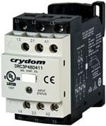
Crydom Inc 的 DRC3P48B411R 是一款三相固态接触器(SSC),额定电压480 VAC,最大负载电流40 A(每相),采用光耦隔离与SCR(可控硅)输出,具备零交叉触发、过热保护及LED状态指示等功能。其典型应用场景包括:

- 工业加热控制:用于电阻炉、热处理设备、注塑机料筒加热等需平稳启停、无机械触点磨损的场合,避免传统接触器拉弧和寿命短问题;
- 泵与风机软启停:配合PLC或温控器,实现三相电机的无冲击启停(非调速),适用于恒压供水、HVAC系统中的循环泵控制;
- 自动化产线执行单元:在PLC控制系统中作为高可靠性功率开关,驱动中等功率三相负载(如传送带电机、压缩机),满足IP20防护等级下的柜内安装需求;
- 洁净/防爆环境辅助控制:因无电弧、低电磁干扰(EMI)、静音运行,适用于食品制药产线、实验室设备及对火花敏感的区域(需配合整体系统防爆认证)。

注意:该型号为非调速型固态接触器,仅支持通/断控制,不适用于变频或相位角调压;使用时需配合适当散热器(推荐自然冷却≥150 cm²或强制风冷),并确保环境温度≤40℃以保障长期可靠运行。
| 参数 | 数值 |
| 产品目录 | |
| 描述 | 480V 5A 120VAC 1NO+1NC RN 3L固态继电器-工业安装 3P 480V 5A 120VAC 1NO+1NC RN 3L |
| 产品分类 | |
| 品牌 | Crydom |
| 产品手册 | |
| 产品图片 |
|
| rohs | 符合RoHS无铅 / 符合限制有害物质指令(RoHS)规范要求 |
| 产品系列 | 继电器与电磁阀,固态继电器-工业安装,Crydom DRC3P48B411RSolicon DRC |
| mouser_ship_limit | 该产品可能需要其他文件才能进口到中国。 |
| 数据手册 | |
| 产品型号 | DRC3P48B411R |
| 产品 | Contactors |
| 产品种类 | 固态继电器-工业安装 |
| 产品类型 | Industrial Mount |
| 供应商器件封装 | - |
| 包装 | 散装 |
| 单位重量 | 14.515 g |
| 商标 | Crydom |
| 商标名 | Solicon |
| 安装类型 | DIN 轨道 |
| 安装风格 | DIN Rail |
| 导通电阻 | - |
| 封装/外壳 | 模块 |
| 控制电压范围 | 120 VAC |
| 最大工作温度 | + 80 C |
| 最小工作温度 | - 30 C |
| 标准包装 | 10 |
| 电压-负载 | 48 ~ 530 V |
| 电压-输入 | 90 ~ 140VAC |
| 电路 | 3PST(3 A 型) |
| 端子类型 | 螺丝端子 |
| 端接类型 | Screw |
| 类型 | Indicator |
| 系列 | DRC3 |
| 继电器类型 | 接触器 |
| 触点形式 | 3PST (3 Form A) |
| 负载电压额定值 | 480 VAC |
| 负载电流 | 5A |
| 负载电流额定值 | 4.8 A |
| 输入电流 | 8 mA |
| 输出类型 | AC |
| 输出设备 | SCR |


- 商务部:美国ITC正式对集成电路等产品启动337调查
- 曝三星4nm工艺存在良率问题 高通将骁龙8 Gen1或转产台积电
- 太阳诱电将投资9.5亿元在常州建新厂生产MLCC 预计2023年完工
- 英特尔发布欧洲新工厂建设计划 深化IDM 2.0 战略
- 台积电先进制程称霸业界 有大客户加持明年业绩稳了
- 达到5530亿美元!SIA预计今年全球半导体销售额将创下新高
- 英特尔拟将自动驾驶子公司Mobileye上市 估值或超500亿美元
- 三星加码芯片和SET,合并消费电子和移动部门,撤换高东真等 CEO
- 三星电子宣布重大人事变动 还合并消费电子和移动部门
- 海关总署:前11个月进口集成电路产品价值2.52万亿元 增长14.8%


PDF Datasheet 数据手册内容提取
Datasheet DIN Rail Mount DRC Series • 7.6 Amp AC Semiconductor Motor Controller • Load voltage range up to 600 VAC • Fits standard 35mm DIN Rail • LED input status indicator • AC or DC control • Zero Voltage (resistive loads) or instantaneous (inductive loads) turn-on output • C-UL-US Listed, IEC Rated, CE & RoHS Compliant, Horsepower Rated • Built-in Overvoltage Protection • Ultra-efficient thermal management design (Patented) Start / Stop Reversing Solicon DRC3 Series are Solid State Contactors intended for instantaneous change of direction is commanded, then it will frequently switching on and off three phase loads up to 5 HP, 600 delay the direction change by 100msec in order to prevent VAC 7.6 Amps. They are available in both contactor versions simultaneous forward and reverse operations. DRC3P and reversing contactor versions DRC3R. All the models of Solicon DRC3 Series combine the benefits and The Solicon Contactor DRC3P is available in either instantaneous advantages of a solid state contactor with the functionality and turn-on (for Motor Control) or zero voltage turn-on (for Resistive simplicity of use of an electromechanical contactor thanks to the Loads). It is available in either 2 or 3 controlled leg versions. The proprietary thermal management technology (Patented) and 2 legs control version is particularly suitable for motor control complete electrical insulation (no grounding required); the circuits where the neutral conductor is not utilized. embedded auxiliary contacts, normally open and/or normally closed, are intended to be used at 18-280VAC. Five different The Solicon Reversing Contactor DRC3R includes an interlock control voltages are available in order to cover most applications. control that allows only off, forward and reverse operation in a All models include overvoltage protection. safe mode while providing high space saving; it switches instantaneously upon application of the control voltage unless an PRODUCT SELECTION Control Voltage Without Auxiliary Contact 1 NO+NC Auxiliary Conctat 2 NO Auxiliary Contact 230 VAC DRC3P48A400, DRC3R48A400 DRC3P48A411 DRC3P48A420, DRC3R48A420 120 VAC DRC3P48B400, DRC3R48B400 DRC3P48B411 DRC3P48B420, DRC3R48B420 48 VAC/DC DRC3P48C400, DRC3R48C400 DRC3P48C411 DRC3P48C420, DRC3R48C420 24 VAC/DC, 24 VAC DRC3P48D400, DRC3R48D400 DRC3P48D411 DRC3P48D420, DRC3R48D420 24 VDC DRC3R48E400 DRC3R48E420 AVAILABLE OPTIONS Operating Voltage Load Current per Phase 40: 400 VAC 4: 7.6 Amp FLA (3R function only) (x2 Controlled Legs Switching Mode 48: 480 VAC & 3R function); (3P function only) 60: 600 VAC 4.8 Amp FLA Blank: Zero Voltage Turn-On Series (3P function only) (x3 Controlled Legs only) R: Instantaneous Turn-On DRC 3P 48 D 4 00 R 2 Function Control Voltage Auxiliary Contacts, Controlled Legs 3P: Contactor A: 208-265 VAC N.O. - N.C. (3P function only) 3R: Reversing Contactor B: 90-140 VAC 00: Not included Blank: 3 Controlled Legs C: 36-55 VAC/DC 11: 1 Solid State Auxiliary 2: 2 Controlled Legs D: 18-30 VAC/DC Contact, Normally Open; (3P function only) 1 Solid State Auxiliary 18-30 VAC Contact, Normally Closed (3R function only) (3P function only) Required for valid part number E: 18-30 VDC 20: 2 Solid State Auxiliary For options only and not required for valid part number (3R function only) Contacts, Normally Open FDE-07-01 REV. A Do not forget to visit us at: www.crydom.com Copyright © 2018 Crydom Inc. Specifications subject to change without notice.
Datasheet DIN Rail Mount OUTPUT SPECIFICATIONS(1) Description DRC3P48x4x DRC3P48x4x2 DRC3P60x4x DRC3P60x4x2 DRC3R40x4x DRC3R48x4x Operating Voltage (47-63Hz) [Vrms] 48-530 48-530 48-600 48-600 48-415 48-510 Transient Overvoltage [Vpk] (2)(3) 1200 1200 1200 1200 1200 1600 Maximum Off-State Leakage Current @ Rated Voltage [mArms] 3.0 3.0 1.0 1.0 5.5 5.5 Maximum Off-State dv/dt @ Maximum Rated Voltage [V/µsec] 500 500 500 500 500 500 Load Current, General Use UL508 /AC51 @40°C [Arms] (4) 5 7.6 5 7.6 7.6 7.6 Load Current, Motor Controller UL508 /AC-53a @480VAC [Arms] (4) 4.8 7.6 4.8 7.6 7.6 7.6 Minimum Load Current [Arms] 0.15 0.15 0.15 0.15 0.15 0.15 Maximum Surge Current [Apk] 1 Cycle 60Hz 750 750 750 750 750 625 Maximum Surge Current [Apk] 1 Cycle 50Hz 716 716 716 716 716 597 Maximum I2t for Fusing (8.33msec)[A2sec] 2330 2330 2330 2330 2330 1621 Maximum I2t for Fusing (10msec)[A2sec] 2560 2560 2560 2560 2560 1779 Maximum On-State Voltage Drop @ Rated Current [Vpk] 1.35 per channel 1.35 per channel 1.35 per channel 1.35 per channel 1.5 per channel 1.5 per channel Minimum Power Factor (with Maximum Load) 0.5 0.5 0.7 0.7 0.5 0.5 Ratings according to UL 508/IEC60947-4-2 [HP/kW]: 240 VAC 1/.75 2/1.5 1/.75 2/1.5 2/1.5 2/1.5 Ratings according to UL 508/IEC60947-4-2 [HP/kW]: 400 VAC 2/1.5 3/2.2 2/1.5 3/2.2 3/2.2 3/2.2 Ratings according to UL 508/IEC60947-4-2 [HP/kW]: 480 VAC 3/2.2 5/3.7 3/2.2 5/3.7 - 5/3.7 Motor Ratings @ 600 VAC [HP/kW] - - 3/2.2 5/3.7 - - INPUT SPECIFICATIONS (1) Description Option A Option B Option C Option D Option E Control Voltage Range (5) 208-265 VAC 90-140 VAC 36-55 VAC / VDC 18-30 VAC / VDC 18-30 VDC Minimum Turn-On Voltage (6) 208 VAC 90 VAC 36 VAC / VDC 18 VAC / VDC 18 VDC Must Turn-Off Voltage 40 VAC 10 VAC 4 VAC / VDC 4 VAC / VDC 4 VDC Minimum Input Current (for on-state) [mA] 6.1 7.5 12 12.5 12.5 Maximum Input Current [mA] 8 13 20 32 32 Nominal Input Impedance [Ohms] 33k 12.5k 3k 0.93k 0.93k Maximum Delay to Turn-On [msec] (7) 30 30 30 20 100 ± 30 Maximum Turn-Off Time [msec] (8) 40 40 40 30 20 SOLID STATE AUXILIARY CONTACTS(1) Description Normally Open Suffix 2x,1x Normally Closed Suffix x1 Operating Voltage Range (47-63Hz) [Vrms] (9) 18-280 18-280 Transient Overvoltage [Vpk] 600 600 Maximum Load Current [Arms] 1 1 Minimum Load Current [mA] 5 5 Maximum Surge Current [Apk] 1 Cycle 60Hz 40 40 Maximum Surge Current [Apk] 1 Cycle 50Hz 38 38 Maximum I2t for Fusing (8.33msec)[A2sec] 6.7 6.7 Maximum I2t for Fusing (10msec)[A2sec] 7.2 7.2 Maximum Off-State Leakage Current @ Rated Voltage [mArms] 0.1 5 mA Minimum Off-State dv/dt @ Maximum Rated Voltage [V/µsec] 500 500 Maximum Delay to Turn-On [msec] (7) 30 80 Maximum Turn-Off Time [msec] 40 40 GENERAL SPECIFICATIONS(1) Description Parameters Dielectric Strength, Input/Output/Base (50/60Hz) (10) 3750 Vrms Minimum Insulation Resistance (@ 500 VDC) 109 Ohms Maximum Capacitance, Input/Output 20 pF Ambient Operating Temperature Range (11) -30 to 80 °C Ambient Storage Temperature Range -40 to 100 °C Weight (typical) 2 Controlled Legs (6.9 oz [197 g]) / 3 Controlled Legs (8.0 oz [228 g]) Housing Material UL94 V-0 Housing Color Black and Light Gray LED Status Indicator (color) (12) Forward (Green) / Reverse (Amber) Short Circuit Current Rating (13) 100kA MTBF (Mean Time Between Failures) at 40°C ambient temperature (14) 1,398,000 hours (159 years) MTBF (Mean Time Between Failures) at 60°C ambient temperature (14) 390,000 hours (44 years) Pollution Degree 2 Protection Degree (15) IP20 Humidity 85% non-condensing Control and Auxiliary Contact Terminal Screw Torque Range (in-lb/Nm) 12 / 1.36 Load Terminal Screw Torque Range (in-lb/Nm) 15 / 1.7 Input Terminal Wire Capacity 18-12 AWG (IEC 1-4 mm2) (stranded /solid) Output Terminal Wire Capacity 18-10 AWG (IEC 1-6 mm2 ) (stranded /solid) Do not forget to visit us at: www.crydom.com Copyright © 2018 Crydom Inc. Specifications subject to change without notice.
Datasheet DIN Rail Mount MECHANICAL SPECIFICATIONS(1) Tolerances: ±0.02 in / 0.5 mm All dimensions are in: inches [millimeters] 3.51 [89] 2.91 [73.9] 0.23 [5.8] A3 13 23 A1 DRC3 3.41 1.23 2.29 2.58 IND. CONT. EQ. 1.68 [86.7] [31.3] [58.3] [65.5] [42.7] XXXX INPUT STATUS 14 24 A2 3.76 [95.6] 1.78 [45.3] TERMINAL SCREW TYPE Fig. 1 Top/Bottom view (Fig. 1) THERMAL DERATE INFORMATION (16) DRC3P (3 controlled legs) DRC3P (2 controlled legs) & DRC3R Single unit(17) Multiple units Single unit(17) Multiple units 6 8 7 5 Amps) 4 Amps) 65 Current ( 3 Current ( 43 Load 2 Load 2 1 1 0 0 0 10 20 30 40 50 60 70 80 0 10 20 30 40 50 60 70 80 Ambient Temperature (ºC) Ambient Temperature (ºC) Do not forget to visit us at: www.crydom.com Copyright © 2018 Crydom Inc. Specifications subject to change without notice.
Datasheet DIN Rail Mount SWITCHING FREQUENCY/LOAD CHARACTERISTIC FOR ALL DEVICES I : Load Operating Current L I : Rated Full Load Current [FLA] R I : Direct-On-Line Inrush Current D t : Load Operating Current Time L I t : Direct-On-Line Inrush Current Time D D t : Cycle Time C tOn : On Time I IR t : Off Time L Off t t D L t t On Off t C MAXIMUM ALLOWABLE NUMBER OF STARTS PER HOUR DEPENDING ON THE STARTING TIME t AND THE ON PERIOD t (as for standard IEC 60947-4-2) FOR ALL DEVICES D On Without overload relay (limit given by the contactor itself) Table 1 Table 2 Table 3 Table 4 • High inrush current (I/I = 4 to 7.2) • High inrush current (I/I = 4 to 7.2) • Low inrush current (I/I < 4 ) • Low inrush current (I/I < 4 ) D R D R D R D R • Full load (I/I= 1) • 60% load (I/I= 0.6) • Full load (I/I= 1) • 60% load (I/I= 0.6) L R L R L R L R t (sec) t (sec) t (sec) t (sec) On On On On t (sec) 0.1 1 10 100 t (sec) 0.1 1 10 100 t (sec) 0.1 1 10 100 t (sec) 0.1 1 10 100 D D D D 0.05 5000 2700 350 35 0.05 6000 3550 350 35 0.05 7450 3200 350 35 0.05 9000 3550 350 35 0.1 3200 1950 350 35 0.1 4100 3000 350 35 0.1 4050 2100 350 35 0.1 5400 3550 350 35 0.2 - 950 320 35 0.2 - 1300 350 35 0.2 - 1200 350 35 0.2 - 1700 350 35 0.4 - 500 280 35 0.4 - 700 320 35 0.4 - 650 320 35 0.4 - 850 350 35 0.8 - 290 160 35 0.8 - 400 320 35 0.8 - 350 280 35 0.8 - 560 350 35 1.6 - - 110 30 1.6 - - 125 35 1.6 - - 180 35 1.6 - - 240 35 3.2 - - 75 25 3.2 - - 90 35 3.2 - - 90 35 3.2 - - 180 35 With overload relay (limit given by the overload relay itself) Table 5 Table 6 Table 7 Table 8 • High inrush current (I/I = 4 to 7.2) • High inrush current (I/I = 4 to 7.2) • Low inrush current (I/I < 4 ) • Low inrush current (I/I < 4 ) D R D R D R D R • Full load (I/I= 1) • 60% load (I/I= 0.6) • Full load (I/I= 1) • 60% load (I/I= 0.6) L R L R L R L R t (sec) t (sec) t (sec) t (sec) On On On On t (sec) 0.1 1 10 100 t (sec) 0.1 1 10 100 t (sec) 0.1 1 10 100 t (sec) 0.1 1 10 100 D D D D 0.05 2200 1650 330 30 0.05 2800 1800 320 35 0.05 5150 2800 260 35 0.05 5600 3200 350 35 0.1 1500 1000 280 28 0.1 1700 1300 310 32 0.1 2850 1920 250 34 0.1 3200 2700 350 35 0.2 - 550 255 26 0.2 - 650 290 30 0.2 - 1100 250 33 0.2 - 1400 350 35 0.4 - 250 150 24 0.4 - 300 200 26 0.4 - 600 200 32 0.4 - 700 350 35 0.8 - 80 60 20 0.8 - 200 90 25 0.8 - 320 200 30 0.8 - 350 280 35 1.6 - - 40 16 1.6 - - 65 25 1.6 - - 120 25 1.6 - - 170 35 3.2 - - 3.2 - - - - 3.2 - - 75 20 3.2 - - 80 25 Do not forget to visit us at: www.crydom.com Copyright © 2018 Crydom Inc. Specifications subject to change without notice.
Datasheet DIN Rail Mount SHORT CIRCUIT AND OVERLOAD PROTECTION FOR ALL DEVICES (Conforming to the IEC60947-4-2 and UL508) IEC standard 60947-4-1 make a distinction between two different types of protection, (called “coordination”), which are designated types “1” and "2". Any short-circuit that occurs is cleared safely by either type of coordination. The only difference between the 2 categories concerns the extent of the SSR damage caused by the short-circuit. Type "1" coordination requires that in the event of a short-circuit, the Solid State Contactor does not endanger personnel or installations, but permanent damage to the SSC is permissible. In this case the SSC may need to be replaced. For this type of co-ordination, the use of fusing or circuit breakers adequate to protect the system and wiring from short circuits, (but not specifically considering SSC protection), can be used. Type "2" coordination requires that under a short-circuit condition, the circuit is interrupted, the SSC does not endanger persons or installations, and in addition the SSR will be able to operate after the fault condition is repaired. Type of coordination 1 Protection by Thermal Magnetic Circuit Breaker(18) Nominal Motor Thermal Magnetic Circuit Breaker Solid State Contactor Solid State Contactor Solid State Contactor Current (Schneider Electric) 2 controlled legs 3 controlled legs Reversing 0.40-0.63 A GV2ME04 / GV2P04 DRC3Pxx4x2 DRC3Pxx4x DRC3Rxx4x 0.63-1 A GV2ME05 / GV2P05 DRC3Pxx4x2 DRC3Pxx4x DRC3Rxx4x 1-1.6 A GV2ME06 / GV2P06 DRC3Pxx4x2 DRC3Pxx4x DRC3Rxx4x 1.6-2.5 A GV2ME07 / GV2P07 DRC3Pxx4x2 DRC3Pxx4x DRC3Rxx4x 2.5-4 A GV2ME08 / GV2P08 DRC3Pxx4x2 DRC3Pxx4x DRC3Rxx4x 4-6.3 A GV2ME10 / GV2P10 DRC3Pxx4x2 DRC3Pxx4x (up to 4.8A) DRC3Rxx4x 6.3-10 A GV2ME14 / GV2P14 DRC3Pxx4x2 (up to 7.6A) - DRC3Rxx4x (up to 7.6A) Protection by overload relays and fuses(18) Nominal Motor Overload Relay Class gG fuses Solid State Contactor Solid State Contactor Solid State Contactor Current (Schneider Electric) (example from Littlefuse) 2 controlled legs 3 controlled legs Reversing 0.40-0.63 A LRD04 CY14X51G16 DRC3Pxx4x2 DRC3Pxx4x DRC3Rxx4x 0.63-1 A LRD05 CY14X51G16 DRC3Pxx4x2 DRC3Pxx4x DRC3Rxx4x 1-1.6 A LRD06 CY14X51G25 DRC3Pxx4x2 DRC3Pxx4x DRC3Rxx4x 1.6-2.5 A LRD07 CY14X51G25 DRC3Pxx4x2 DRC3Pxx4x DRC3Rxx4x 2.5-4 A LRD08 CY14X51G25 DRC3Pxx4x2 DRC3Pxx4x DRC3Rxx4x 4-6.3 A LRD10 CY14X51G40 DRC3Pxx4x2 DRC3Pxx4x(up to 4.8A) DRC3Rxx4x 6.3-10 A LRD14 CY14X51G40 DRC3Pxx4x2 (up to 7.6A) - DRC3Rxx4x (up to 7.6A) Type of coordination 2 Protection by overload relays and fuses(18) Nominal Motor Overload Relay Semiconductor fuses with less than 1621A2S Solid State Contactor Solid State Contactor Solid State Contactor Current (Schneider Electric) Littlefuse SIBA (Cylindric) Ferraz (Cylindric) 2 controlled legs 3 controlled legs Reversing 0.40-0.63 A LRD04 LA50QS40-4 50.058.06.40 A093909 DRC3Pxx4x2 DRC3Pxx4x DRC3Rxx4x 0.63-1 A LRD05 LA50QS40-4 50.058.06.40 A093909 DRC3Pxx4x2 DRC3Pxx4x DRC3Rxx4x 1-1.6 A LRD06 LA50QS40-4 50.058.06.40 A093909 DRC3Pxx4x2 DRC3Pxx4x DRC3Rxx4x 1.6-2.5 A LRD07 LA50QS40-4 50.058.06.40 A093909 DRC3Pxx4x2 DRC3Pxx4x DRC3Rxx4x 2.5-4 A LRD08 LA50QS40-4 50.058.06.40 A093909 DRC3Pxx4x2 DRC3Pxx4x DRC3Rxx4x 4-6.3 A LRD10 LA50QS40-4 50.058.06.40 A093909 DRC3Pxx4x2 DRC3Pxx4x (up to 4.8A) DRC3Rxx4x 6.3-10 A LRD14 LA50QS40-4 50.058.06.40 A093909 DRC3Pxx4x2 (up to 7.6A) - DRC3Rxx4x (up to 7.6A) Note: All the Schneider Electric Thermal magnetic circuit breakers GV2 family (GV2ME and GV2P) is fully mechanical compatible with the DRC contactor using the GV2AF3 connection block. All the Schneider Electric Overload relay LRD family is fully mechanical compatible with the DRC contactor without the need of any adapter. The DRC Series can accept the LAD7C1 module (pre-wiring kit allowing direct connection of the NC contact of relay LRD to the contactor) Do not forget to visit us at: www.crydom.com Copyright © 2018 Crydom Inc. Specifications subject to change without notice.
Datasheet DIN Rail Mount WIRING AND BLOCK DIAGRAM DRC3P CONTACTOR(19) DRC3Pxx400 DRC3Pxx411 DRC3Pxx420 48-530 VAC, 50-60 Hz 48-600 VAC, 50-60 Hz L1 L1 L2 L2 L3 L3 Short circuit and overload current protection (see page 5) / > / > / > / > / > / > / > / > / > TL11XXXXDRC3TLINP22D.X CXONXT. 4EQ0S.0ITNATLXPT33UXUTAAS12 COINNPTURTOL 1st Auxiliary Contact (18 - 280 VAC) Normally Open 2nd Auxiliary Contact (18 - 280 VAC) Normally Closed TL11XXXXDR11C343TLINP22D.X CXON22XT12. 4EQ1S.1ITNXATLPT33UXUTAAS12 COINNPTURTOL 1st Auxiliary Contact (18 - 280 VAC) Normally Open 2nd Auxiliary Contact (18 - 280 VAC) Normally Open TL11XXXXDR11C343TLINP22D.X CXON22XT34. 4EQ2S.0ITNATLXPT33UXUTAAS12 COINNPTURTOL Motor Controller / General Use / T1 T2 T3 AC-53a Application T1 T2 T3 AC-51 Application T1 T2 T3 T1 T2 T3 T1 T2 T3 M 3 DRC3P DRC3P (3 controlled legs model) (2 controlled legs model) Main Circuit Main Circuit L1 L2 L3 A1 L1 L2 L3 A1 T1 T2 T3 A2 T1 T2 T3 A2 DRC3Pxx400 DRC3Pxx420 DRC3Pxx411 (2 Normally Open) (1 Normally Open - 1 Normally Closed) Auxiliary Contacts Auxiliary Contacts 13 23 13 21 Without Auxiliary Contacts 14 24 14 22 Do not forget to visit us at: www.crydom.com Copyright © 2018 Crydom Inc. Specifications subject to change without notice.
Datasheet DIN Rail Mount DRC3R REVERSING CONTACTOR(20) DRC3Rxx400 DRC3Rxx420 48-415 VAC, 50 - 60 Hz 48-510 VAC, 50 - 60 Hz L1 L1 L2 L2 L3 L3 Short circuit and overload current protection (see page 5) / > / > / > / > / > / > LA13 L2 L3A1 mally Open mally Open AL31 13L2 23 L3A1 Nor Nor C(ROIeNNvPeTUrRsTOeL) T1XXXDXRC3TIRN2DX. CXONXT.4 E0QS.0ITNXATPT3XUUTAS2 (CC(CFOOIIooNNNNrmwPPTTmUUaRRoTTrOOdnLL)) 1st Auxiliary Contact (18 - 280 VAC) 2nd Auxiliary Contact (18 - 280 VAC) C(ROIeNNvPeTUrRsTOeL) T1XXXDXR1C43TIRN2DX. CXONX2T4.4 E2QS.0ITNXATPT3XUUTAS2 (CC(CFOOIIooNNNNrmwPPTTmUUaRRoTTrOOdnLL)) T1 T2 T3 Motor Controller / T1 T2 T3 AC-53a Application T1 T2 T3 M 3 Overload current protection needs to be considered DRC3R Forward Reverse Forward Reverse L1 L2 L3 A1 L1 L2 L3 A3 13 23 14 24 T1 T2 T3 A2 T1 T2 T3 A2 DRC3Rxx420 models only Do not forget to visit us at: www.crydom.com Copyright © 2018 Crydom Inc. Specifications subject to change without notice.
Datasheet DIN Rail Mount TIMING DIAGRAM TIMING DIAGRAM FOR DRC3R Input/Output 1 2 3 4 5 6 7 8 9 10 Input A1 Input A3 FWD Direction 100 msec 100 msec REV Direction 100 msec interlock STEP DESCRIPTION 1, 4, 10 Initial Condition. A1 & A3 open 2 A1 is activated, FWD Output waits for 100msec Input A1 Input A3 FWD REV 3, 9 FWD direction is activated Open Open Off Off 4 A1 changes to off. FWD Output is disabled at the same time Close Open On Off 5 A3 is activated. REV Outputs waits for 100msec Open Close Off On 6 REV direction is On Close Close Off Off 7 Interlock fuction is activated. REV is disabled due to A1 & A3 both being active 8 A3 is open, A1 is closed, activation delayed 100msec AGENCY APPROVALS Agency Approvals Certification in accordance with: United States Standard for Industrial Control Equipment - UL 508 and Canadian Standard Association for Industrial Control Equipment – C22.2 No. 14. DRC3 series conforms to the harmonized EN standard EN/IEC 60947-4-2 Electromagnetic Compatibility: IEC 61000-4-2 : Electrostatic Discharge – Level 3 IEC 61000-4-4 : Electrically Fast Transients – Level 3 IEC 61000-4-5 : Electrical Surges – Level 3 Vibration Resistance: IEC 60068-2-6 : Amplitude Range 10-55 Hz, Displacement 0.75mm Shock Resistance: IEC 60068-2-27 : Peak Acceleration 15g, Duration11msec. E116949 Do not forget to visit us at: www.crydom.com Copyright © 2018 Crydom Inc. Specifications subject to change without notice.
Datasheet DIN Rail Mount ACCESSORIES FOR ALL DEVICES Recommended Accessories Motor Nominal Bimetal Electronic Thermal Magnetic Circuit Thermal Magnetic Circuit Current Overload Relay Overload Relay Breaker (Push Button) Breaker (Selector) 0.40 - 0.63 A LRD04 LR97 D015xx GV2ME04 GV2P04 0.63 - 1 A LRD05 LR97 D015xx GV2ME05 GV2P05 1 - 1.6 A LRD06 LR97 D07xx GV2ME06 GV2P06 1.6 - 2.5 A LRD07 LR97 D07xx GV2ME07 GV2P07 2.5 - 4 A LRD08 LR97 D07xx GV2ME08 GV2P08 4 - 6.3 A LRD10 LR97 D25xx GV2ME10 GV2P10 6.3 - 10 A LRD14 LR97 D25xx GV2ME14 GV2P14 Fully compatible with Schneider Electric thermal overload relays & thermal magnetic circuit breakers Note: All the Schneider Electric Thermal magnetic circuit breakers GV2 family (GV2ME and GV2P) is fully mechanical compatible with the DRC contactor using the GV2AF3 connection block. All the Schneider Electric Overload relay LRD family is fully mechanical compatible with the DRC contactor without the need of any adapter. The DRC Series can accept the LAD7C1 module (pre-wiring kit allowing direct connection of the NC contact of relay LRD to the contactor) When the LAD7C1 module is used, the common terminal for the control input is not anymore the ”A2” terminal of DRC but it is the “96” terminal of the overload relay. ID Marker Strips CNLB, CNLN, CNL2 Packages of 10 plastic strips comprising 10 Blank Strips individual markers which can be placed for easy identification during the use of multiple units. Part no.: CNLB Numbered 1 to 10 Strips Numbered 11 to 20 Strips Part no.: CNLN Part no.: CNL2 Do not forget to visit us at: www.crydom.com Copyright © 2018 Crydom Inc. Specifications subject to change without notice.
Datasheet DIN Rail Mount GENERAL NOTES (1) All parameters at 25°C unless otherwise specified. (2) For DRC3P relay will self trigger between 900-1200V, Not suitable for capacitive loads. (3) For DRC3R over rated voltage internal self protection will be activated increasing leakage current. (4) Mounted in the Vertical position. (5) On DRC3R models the range for option D is 18-30 VAC. (6) For low temperature operation consider nominal control voltage. (7) For DRC3R the turn-on time is 100msec ± 30msec. (8) When is complete removed the control signal. For DRC3R the turn-off time is 20msec. (9) Operating voltage range 18-30 VDC is also valid when used to latch the DRC contactor control input. (10) For input to auxiliary output the dielectric strength is 2.5kV. (11) UL approval up to 40°C surrounding temperature. (12) Reverse Amber Indicator is for DRC3R models only. (13) 100kA, 480VAC, when protected with CC class fuses rated 600VAC, 20 A or equivalent. (14) All parameters at 50% power rating and 100% duty cycle (contact Crydom tech support for detailed report). (15) IP20 rating is not associated with the UL approval. (16) Derate information is valid when DCR contactors are used with or without accessories, installed on top and/or bottom. (17) Minimum spacing to obtain max. current is 22mm between adjacent units. (18) Combinations of these Protective Devices and Solid State Contactor have not been evaluated by UL. (19) For DRC3P models external loads can be connected in parallel to the control input. (20) DRC3R internal safety interlock circuit prevents the product to work if any leakage current is present in the control input currently not enabled. Rev. 062918 ECN#20485 Do not forget to visit us at: www.crydom.com Copyright © 2018 Crydom Inc. Specifications subject to change without notice.
Datasheet DIN Rail Mount DANGER / PELIGRO / DANGER /GEFAHR / PERICOLO / 危险 存在电击、 HAZARD OF RIESGO DE RISQUE DE GEFAHR EINES RISCHIO DI ELECTRIC DESCARGA DESCHARGE ELEKTRISCHE SCOSSA 爆炸或电弧 SHOCK, ELECTRICA O ELECTRIQUE N SCHLAGES ELETTRICA O 闪烁危险 EXPLOSION, EXPLOSION. OU EXPLOSION ODER EINER DELL’ESPLOSIONE. OR ARC FLASH. • Desconectar • Eteindre EXPLOSION. • Spenga tutta • 在操作此设 • Disconnect all todos los toutes les • Stellen Sie l'alimentazione 备之前请先 power before suministros de sources jeglichen che fornisce 关闭电源。 installing or energia a este d'énergie de Strom ab, der questa working with equipo antes cet appareil dieses Gerät apparecchiatura 若不遵守这些说明, this equipment. de trabajar avant de versorgt, bevor prima di lavorare con este equipo. travailler Sie an dem a questa 可能会导致严重的 • Verify all dessus de cet Gerät Arbeiten apparecchiatura 人身伤害甚至死亡。 connections • Verificar todas appareil durchführen and replace all las conexiones • Verificare tutti • Vor dem covers before y colocar todas • Vérifier tous i collegamenti Drehen auf turning on las tapas antes connections, et e sostituire Energie alle power. de energizer remettre tous tutte le coperture Anschlüsse el equipo. couverts en prima Failure to follow olace avant de überprüfen dell’accensione these El mettre sous und alle instructions will incumplimiento Abdeckungen L'omissione di result in death de estas De non-suivi de ersetzen. queste istruzioni or serious injury. instrucciones ces instructions Unterlassung provocherà la puede provocar provoquera la dieser morte o la muerte o mort ou des Anweisungen lesioni serie lesiones serias. lésions sérieuses können zum sérieuses. Tode oder zu schweren Verletzungen führen. WARNING / AVERTISSEMENT / WARNUNG /ADVERTENCIA / AVVERTENZA / 警告 RISK OF MATERIAL DAMAGE AND HOT RISQUE DE DOMMAGE MATERIEL ET DE GEFAHR VON MATERIALSCHÄDEN UND ENCLOSURE SURCHAUFFE DU BOITIER GEHÄUSEERHITZUNG • The product's side panels may be hot, allow • Les panneaux latéraux du produit peuvent être • Die Seitenwände können heiß sein. Lassen Sie the product to cool before touching. chauds. Laisser le produit refroidir avant de le das Produkt abkühlen, bevor Sie es berühren. • Follow proper mounting instructions including toucher. • Beachten Sie die Montageanweisungen, torque values. • Respecter les consignes de montage, et • Führen Sie keine Flüssigkeiten oder • Do not allow liquids or foreign objects to enter notamment les couples de serrage. Fremdkörper in das Produkt ein. this product. • Ne pas laisser pénétrer de liquide ni de corps étrangers à l'intérieur du produit. Le non-respect de cette directive peut entraîner, Die Nichtbeachtung dieser Anweisung kann Failure to follow these instructions can result in des lésions corporelles graves ou des Körperverletzung oder Materialschäden serious injury, or equipment damage. dommages matériels. zur Folge haben. RIESGO DE DAÑOS MATERIALES Y DE 材料损坏和高温外壳的危险性 RISCHIO DI DANNI MATERIALI E D'INVOLUCRO SOBRECALENTAMIENTO DE LA UNIDAD CALDO • 产品的一侧面板可能很热,在其冷却前请 • Los paneles laterales del producto pueden • I pannelli laterali dell'apparecchio possono 不要触碰。 estar calientes. Esperar que el producto se scottare; lasciar quindi raffreddare il prodotto • 遵照正确的安装说明,包括扭矩值。 enfríe antes de tocarlo. • Respetar las instrucciones de montaje, y en prima di toccarlo. • 请勿让液体及其他异物进入本产品。 • Seguire le istruzioni di montaggio corrette. particular los pares de apretado. • Non far entrare liquidi o oggetti estranei in questo • No dejar que penetren líquidos o cuerpos apparecchio. extraños en el producto. La mancata osservanza di questa precauzione può 如不能正确执行这些操作说明, Si no se respetan estas precauciones pueden causare gravi rischi per l'incolumità personale o 极有可能造成严重人体伤害或者设备的损坏。 producirse graves lesiones, daños materiales. danni alle apparecchiature. Do not forget to visit us at: www.crydom.com Copyright © 2018 Crydom Inc. Specifications subject to change without notice.
Datasheet DIN Rail Mount ANNEX - ENVIRONMENTAL INFORMATION The environmental information disclosed in this annex including the EIP Pollution logo are in compliance with People’s Republic of China Electronic Industry Standard SJ/T11364 – 2006, Marking for Control of Pollution Caused by Electronic Information Products. Part Toxic or hazardous Substance and Elements Name Lead Mercury Cadmium Hexavalent Polybrominated Polybrominated (Pb) (Hg) (Cd) Chromium biphenyls diphenyl ethers (Cr (VI)) (PBB) (PBDE) Semiconductor die Solder 附件 - 环保信息 此附件所标示的包括电子信息产品污染图标的环保信息符合中华人民共和国电子行业标准 SJ/T11364 - 2006, 电子信息产品污染控制标识要求。 部件 有毒有害物质或元素 名称 铅 汞 镉 六价铬 多溴联苯 多溴二苯醚 (Pb) (Hg) (Cd) (Cr (VI)) (PBB) (PBDE) 半导体芯片 焊接点 50 Do not forget to visit us at: www.crydom.com Copyright © 2018 Crydom Inc. Specifications subject to change without notice.
Mouser Electronics Authorized Distributor Click to View Pricing, Inventory, Delivery & Lifecycle Information: S ensata: DRC3R40D400 DRC3P48B400R2 DRC3R48A420 DRC3P48B400R DRC3R40B400 DRC3R40A400 DRC3P48A400R2 DRC3P48A400R DRC3P48D411R2 DRC3P48D400R2 DRC3P48D420R2 DRC3R48D420 DRC3P48D400R DRC3R48B420 DRC3P48D420 DRC3P48D4202 DRC3P48D420R DRC3R40A420 DRC3R40B420 DRC3R40D420 DRC3R48A400 DRC3R48B400 DRC3R48D400 DRC3P48A400 DRC3P48A4002 DRC3P48A411 DRC3P48A4112 DRC3P48A411R DRC3P48A411R2 DRC3P48A420 DRC3P48A4202 DRC3P48A420R DRC3P48A420R2 DRC3P48B400 DRC3P48B4002 DRC3P48B411 DRC3P48B4112 DRC3P48B411R DRC3P48B411R2 DRC3P48B420 DRC3P48B4202 DRC3P48B420R DRC3P48B420R2 DRC3P48D400 DRC3P48D4002 DRC3P48D411 DRC3P48D4112 DRC3P48D411R DRC3P48C420 DRC3P48C420R2 DRC3P48C4002 DRC3P48C4202 DRC3R48C420 DRC3P60D4112 DRC3P60D420 DRC3P60D400R2 DRC3R48E400 DRC3P60C4202 DRC3P60D4002 DRC3P60D411R2 DRC3R40E400 DRC3P60A411R DRC3P60D400 DRC3P60A400 DRC3P60A4002 DRC3P60A411 DRC3P60A420R2 DRC3P60C4112 DRC3P60C4002 DRC3P60D411 DRC3R48E420 DRC3P60C420R DRC3P60B4112 DRC3P60B420 DRC3P60D400R DRC3P48C411R DRC3P48C400R2 DRC3P48C4112 DRC3R40C400 DRC3P60B420R DRC3P60C411 DRC3P60B411R2 DRC3P60B4202 DRC3P60C420 DRC3P60B4002 DRC3P60C411R2 DRC3P60A420R DRC3P60B411 DRC3R40C420 DRC3P60A4112 DRC3P60A420 DRC3P60B400R2 DRC3P60B411R DRC3P60D420R DRC3P60D420R2 DRC3R40E420 DRC3P60A400R2 DRC3P60C400R2 DRC3P60A411R2 DRC3P60C411R