ICGOO在线商城 > 开发板,套件,编程器 > 编程器,仿真器和调试器 > DEBUGADPTR1-USB

 Datasheet下载
- 型号: DEBUGADPTR1-USB
- 制造商: Silicon Laboratories
- 库位|库存: xxxx|xxxx
- 要求:
| 数量阶梯 | 香港交货 | 国内含税 |
| +xxxx | $xxxx | ¥xxxx |
查看当月历史价格
查看今年历史价格
DEBUGADPTR1-USB产品简介:
ICGOO电子元器件商城为您提供DEBUGADPTR1-USB由Silicon Laboratories设计生产,在icgoo商城现货销售,并且可以通过原厂、代理商等渠道进行代购。 DEBUGADPTR1-USB价格参考¥429.99-¥429.99。Silicon LaboratoriesDEBUGADPTR1-USB封装/规格:编程器,仿真器和调试器, 8051 - Debugger。您可以下载DEBUGADPTR1-USB参考资料、Datasheet数据手册功能说明书,资料中有DEBUGADPTR1-USB 详细功能的应用电路图电压和使用方法及教程。
Silicon Labs的DEBUGADPTR1-USB是一款专为嵌入式开发设计的编程器、仿真器和调试器,主要用于支持基于Silicon Labs微控制器(MCU)和无线SoC(System on Chip)的开发环境。这款设备的应用场景非常广泛,特别适用于以下几种情况:

 1. 嵌入式系统开发
   DEBUGADPTR1-USB是嵌入式开发工程师在进行固件开发时不可或缺的工具。它能够与Silicon Labs的MCU和无线SoC配合使用,帮助开发者快速烧录程序代码到目标芯片中,并通过仿真功能实时监控和调试程序运行状态。该设备支持多种通信接口(如JTAG、SWD等),确保了与不同型号的MCU或SoC之间的兼容性。

 2. 无线产品开发
   对于开发无线产品的工程师来说,DEBUGADPTR1-USB提供了强大的调试和仿真功能。它不仅可以用于传统的有线调试,还可以支持无线协议栈的开发和调试。例如,在开发基于Zigbee、Bluetooth、Thread等无线协议的产品时,DEBUGADPTR1-USB可以帮助工程师更高效地进行协议栈的调试和优化,确保无线通信的稳定性和可靠性。

 3. 物联网(IoT)应用
   在物联网设备的开发过程中,DEBUGADPTR1-USB可以显著提高开发效率。物联网设备通常需要集成多种传感器、执行器以及复杂的通信协议,而DEBUGADPTR1-USB能够帮助开发者快速定位并解决这些问题。通过其强大的调试功能,开发者可以在实际环境中测试设备的行为,确保设备在各种条件下的正常运行。

 4. 教育和培训
   在嵌入式系统和物联网相关的教育和培训中,DEBUGADPTR1-USB也是一个非常实用的教学工具。学生可以通过该设备学习如何编写、烧录和调试嵌入式程序,熟悉常见的调试技巧和方法。此外,它还支持多种开发平台(如Simplicity Studio),使得教学过程更加直观和高效。

 5. 硬件验证与测试
   在硬件设计完成后,DEBUGADPTR1-USB可用于验证硬件的功能是否符合预期。通过连接到目标板,开发者可以使用该设备进行硬件初始化、寄存器配置等操作,确保硬件工作正常。同时,它也可以用于测试硬件的性能,帮助开发者优化硬件设计。

总之,DEBUGADPTR1-USB是一款功能强大且易于使用的开发工具,适用于从嵌入式系统到无线产品再到物联网应用的多个领域,极大地提高了开发效率和产品质量。
| 参数 | 数值 |
| 产品目录 | 编程器,开发系统嵌入式解决方案 |
| 描述 | USB DEBUG ADAPTER 8-BIT插座和适配器 USB Debug Adapter FORC8051FXXXMCU |
| 产品分类 | 内电路编程器、仿真器以及调试器工程工具 |
| 品牌 | Silicon LabsSilicon Laboratories Inc |
| 产品手册 | |
| 产品图片 |
|
| rohs | 符合RoHS含铅 / 不符合限制有害物质指令(RoHS)规范要求 |
| 产品系列 | 嵌入式开发工具,嵌入式工具与配件,插座和适配器,Silicon Labs DEBUGADPTR1-USB- |
| 数据手册 | |
| 产品型号 | DEBUGADPTR1-USBDEBUGADPTR1-USB |
| 产品 | USB Debug Adapters |
| 产品目录页面 | |
| 产品种类 | 插座和适配器 |
| 其它名称 | 336-1182 |
| 内容 | 板,线缆 |
| 单位重量 | 50 mg |
| 商标 | Silicon Labs |
| 接口类型 | USB |
| 描述/功能 | USB debug adapter for C8051Fxxx MCUs |
| 标准包装 | 1 |
| 用于 | C8051Fxxx Target Boards |
| 类型 | 调试程序 |
| 系列 | DEBUGADPTR1 |
| 配套使用产品/相关产品 | C8051xxx 8-位 MCU |


.jpg)

- 商务部:美国ITC正式对集成电路等产品启动337调查
- 曝三星4nm工艺存在良率问题 高通将骁龙8 Gen1或转产台积电
- 太阳诱电将投资9.5亿元在常州建新厂生产MLCC 预计2023年完工
- 英特尔发布欧洲新工厂建设计划 深化IDM 2.0 战略
- 台积电先进制程称霸业界 有大客户加持明年业绩稳了
- 达到5530亿美元!SIA预计今年全球半导体销售额将创下新高
- 英特尔拟将自动驾驶子公司Mobileye上市 估值或超500亿美元
- 三星加码芯片和SET,合并消费电子和移动部门,撤换高东真等 CEO
- 三星电子宣布重大人事变动 还合并消费电子和移动部门
- 海关总署:前11个月进口集成电路产品价值2.52万亿元 增长14.8%
.jpg)


PDF Datasheet 数据手册内容提取
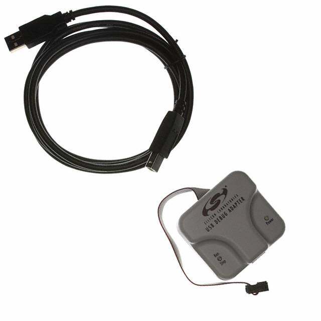
8-Bit USB Debug Adapter 8-BIT USB DEBUG ADAPTER USER’S GUIDE 1. Introduction The 8-bit USB Debug Adapter (UDA) provides the interface between the PC’s USB port and the Silicon Labs 8-bit target device’s in-system debug/programming circuitry. The 10-pin ribbon cable connects the adapter to the target board and the target device’s debug interface. Figure 1. 8-Bit USB Debug Adapter Visit www.silabs.com/8bit-uda for ordering information. 2. Relevant Documentation Application notes can be found on the 8-bit MCU Application Notes web page: www.silabs.com/appnotes. AN124: Pin Sharing Techniques for the C2 Interface—Describes in detail the debug interface pin sharing feature for C2 devices, which enables debugging and use of the /RST and GPIO pins shared with C2CK and C2D. AN117: Using C8051Fxxx On-Chip Interface Utilities DLL—The SiUtil DLL discussed in this document uses the USB Debug Adapter to program the memory space of C2 and JTAG devices. AN134: Multiple-Device JTAG Configuration in the Silicon Labs IDE—Configuration in the IDE and using the USB Debug Adapter for devices in a JTAG chain. Rev. 0.3 1/15 Copyright © 2015 by Silicon Laboratories 8-Bit USB Debug Adapter
8-Bit USB Debug Adapter 3. Pinout Specification The 8-Bit USB Debug Adapter supports both Silicon Laboratories JTAG and C2 debug interfaces, and the adapter is powered from the USB connection to the PC. The UDA is also capable of providing power to the target device or other circuitry via pin 10 of the connector. Table1 shows the pin definitions for the UDA keyed connector. The part number for the matching shrouded and keyed connector for a PCB is 2510-6002UB from 3M. The USB Debug Adapter can automatically change the communication voltage level based on the level detected on pin 7 of the connector. As a result, this pin should be pulled high with a strong pull-up (~1kΩ) for noise immunity purposes and not pulled down to ground. Notes: • The USB Debug Adapter requires a target system clock of 32kHz or greater. • With the default settings, the USB Debug Adapter can supply up to 100 mA to a target system. Table 1. USB Debug Adapter Debug Connector Pin Descriptions Pin # Description Details 1 Not Connected 2 GND (Ground) 3 GND (Ground) 4 TCK / C2D JTAG TCK or C2 Data 5 TMS / C2CK pin share JTAG TMS or C2 Clock pin sharing 6 TDO / C2D pin share JTAG TDO or C2 Data pin sharing 7 TDI / C2CK JTAG TDI or C2 Clock signal This pin is used by the UDA to sense and set the logic voltage level. This pin should never have a pull-down to ground. 8 Not Connected 9 GND (Ground) 10 USB Power 5 V power from the UDA 1 3 5 7 9 2 4 6 8 10 Figure 2. 8-Bit USB Debug Adapter Connector 2 Rev. 0.3
8-Bit USB Debug Adapter 4. Minimum C2 Programming Connections The minimum required programming connections for the C2 interface are C2D (pin 4), C2CK (pin 7), and ground (pins 2, 3, or 9). 5. Hardware Setup using a USB Debug Adapter Connect a target board to a PC running the Silicon Laboratories IDE via the USB Debug Adapter as shown in Figure3. 1. Connect the USB Debug Adapter’s 10-pin ribbon cable to the JTAG or Debug connector on the target board. 2. Connect one end of a standard USB cable to the USB connector on the USB Debug Adapter. 3. Connect the other end of the USB cable to a USB Port on the PC. 4. Power the target board. Notes: • Use theR eset button in the IDE to reset the target when connected using a USB Debug Adapter. • Remove power from the target board and the USB Debug Adapter before connecting or disconnecting the ribbon cable from the target board. Connecting or disconnecting the cable when the devices have power can damage the device and/or the USB Debug Adapter. 1 3 2 Figure 3. Hardware Setup using a USB Debug Adapter 6. USB Drivers The USB Debug Adapter uses the Human Interface Device (HID) USB interface to communicate with the PC. Since most operating systems have this driver automatically built in, no drivers need to be installed to use the UDA. Rev. 0.3 3
8-Bit USB Debug Adapter 7. Software Setup using a USB Debug Adapter The Silicon Laboratories Integrated Development Environment (IDE) along with other software tools are provided for device development and debugging. The IDE is available for download from the Silicon Laboratories website (www.silabs.com/mcudownloads) and is also available on microcontroller development kit CD-ROMs. 7.1. Configuring the USB Debug Adapter in the Silicon Labs IDE Once the IDE has been installed and the hardware has been connected as shown in Section5, follow the steps below to built a project, connect and download to a target board using the USB Debug Adapter. 1. Select ProjectOpen Project... to open a previously saved project. 2. Before connecting to the target device, several connection options may need to be set. Open the Connection Options window (shown in Figure4) by selecting OptionsConnection Options... in the IDE menu. 3. Select USB Debug Adapter in the Serial Adapter section. 4. If more than one adapter is connected, choose the appropriate serial number from the drop-down list. 5. Check the Power target after disconnect option if the target board is currently being powered by the USB Debug Adapter. The board will remain powered after a software disconnect by the IDE. 6. Next, the correct Debug Interface must be selected. Check the Debug Interface corresponding to the Silicon Laboratories device on the target board. 7. Once all the selections are made, click the OK button to close the window. 8. Click the Connect button in the toolbar or select DebugConnect from the menu to connect to the device. 9. Download the project to the target by clicking the Figure 4. Connection Options Download Code button in the toolbar. 10. Save the project when finished with the debug session to preserve the current target build configuration, editor settings and the location of all open debug views. To save the project, select ProjectSave Project As... from the menu. Create a new name for the project and click on Save. 4 Rev. 0.3
8-Bit USB Debug Adapter 8. Schematics ) 2 f o 1 ( c i t a m e h c S r e t p a d A g u b e D B S U t i B - 8 . 5 e r u g i F Rev. 0.3 5
8-Bit USB Debug Adapter ) 2 f o 2 ( c i t a m e h c S r e t p a d A g u b e D B S U t i B - 8 . 6 e r u g i F 6 Rev. 0.3
Simplicity Studio One-click access to MCU and wireless tools, documentation, software, source code libraries & more. Available for Windows, Mac and Linux! IoT Portfolio SW/HW Quality Support and Community www.silabs.com/IoT www.silabs.com/simplicity www.silabs.com/quality community.silabs.com Disclaimer Silicon Laboratories intends to provide customers with the latest, accurate, and in-depth documentation of all peripherals and modules available for system and software implementers using or intending to use the Silicon Laboratories products. Characterization data, available modules and peripherals, memory sizes and memory addresses refer to each specific device, and "Typical" parameters provided can and do vary in different applications. Application examples described herein are for illustrative purposes only. Silicon Laboratories reserves the right to make changes without further notice and limitation to product information, specifications, and descriptions herein, and does not give warranties as to the accuracy or completeness of the included information. Silicon Laboratories shall have no liability for the consequences of use of the information supplied herein. This document does not imply or express copyright licenses granted hereunder to design or fabricate any integrated circuits. The products must not be used within any Life Support System without the specific written consent of Silicon Laboratories. A "Life Support System" is any product or system intended to support or sustain life and/or health, which, if it fails, can be reasonably expected to result in significant personal injury or death. Silicon Laboratories products are generally not intended for military applications. Silicon Laboratories products shall under no circumstances be used in weapons of mass destruction including (but not limited to) nuclear, biological or chemical weapons, or missiles capable of delivering such weapons. Trademark Information Silicon Laboratories Inc., Silicon Laboratories, Silicon Labs, SiLabs and the Silicon Labs logo, CMEMS®, EFM, EFM32, EFR, Energy Micro, Energy Micro logo and combinations thereof, "the world’s most energy friendly microcontrollers", Ember®, EZLink®, EZMac®, EZRadio®, EZRadioPRO®, DSPLL®, ISOmodem ®, Precision32®, ProSLIC®, SiPHY®, USBXpress® and others are trademarks or registered trademarks of Silicon Laboratories Inc. ARM, CORTEX, Cortex-M3 and THUMB are trademarks or registered trademarks of ARM Holdings. Keil is a registered trademark of ARM Limited. All other products or brand names mentioned herein are trademarks of their respective holders. Silicon Laboratories Inc. 400 West Cesar Chavez Austin, TX 78701 USA http://www.silabs.com
Mouser Electronics Authorized Distributor Click to View Pricing, Inventory, Delivery & Lifecycle Information: S ilicon Laboratories: DEBUGADPTR1-USB