 Datasheet下载
- 型号: DE2F3KY103MB3BM02F
- 制造商: Murata
- 库位|库存: xxxx|xxxx
- 要求:
| 数量阶梯 | 香港交货 | 国内含税 |
| +xxxx | $xxxx | ¥xxxx |
查看当月历史价格
查看今年历史价格
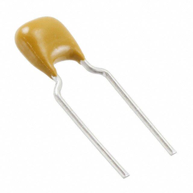
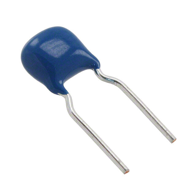
DE2F3KY103MB3BM02F产品简介:
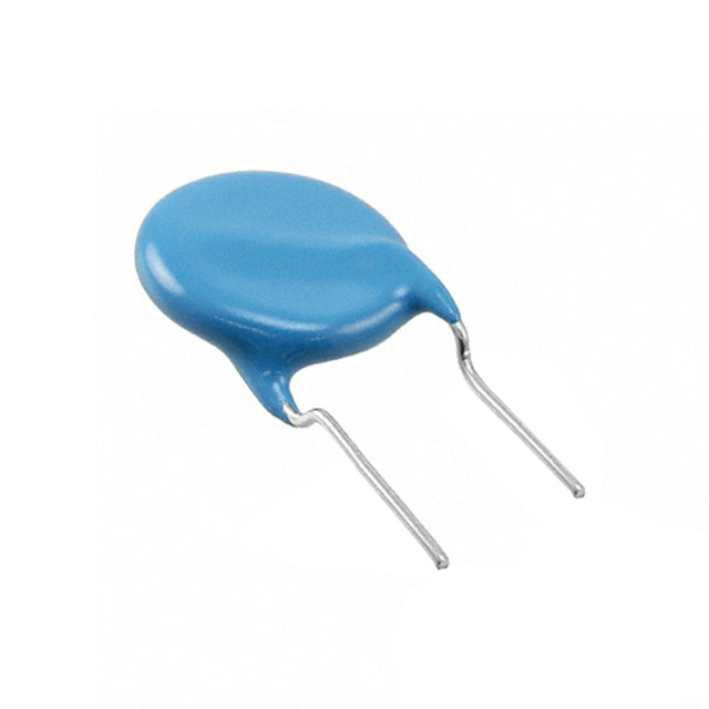
ICGOO电子元器件商城为您提供DE2F3KY103MB3BM02F由Murata设计生产,在icgoo商城现货销售,并且可以通过原厂、代理商等渠道进行代购。 DE2F3KY103MB3BM02F价格参考¥1.92-¥5.49。MurataDE2F3KY103MB3BM02F封装/规格:陶瓷电容器, 10000pF ±20% 250VAC 陶瓷电容器 F 径向,圆片式。您可以下载DE2F3KY103MB3BM02F参考资料、Datasheet数据手册功能说明书,资料中有DE2F3KY103MB3BM02F 详细功能的应用电路图电压和使用方法及教程。
Murata Electronics North America的陶瓷电容器型号DE2F3KY103MB3BM02F,属于多层陶瓷电容器(MLCC)的一种。该型号电容器主要应用于以下场景:

1. 电源管理电路:用于DC-DC转换器、AC-DC电源模块等场合,作为输入/输出滤波电容,以稳定电压、降低纹波和噪声。

2. 工业控制设备:适用于工业自动化系统、PLC(可编程逻辑控制器)以及传感器模块中,提供稳定的电源去耦和信号滤波功能。

3. 通信设备:可用于基站、光模块、路由器和交换机等通信基础设施中,支持高频信号处理和电源稳定。

4. 汽车电子系统:符合高可靠性要求,适用于车载电源系统、车载信息娱乐系统(IVI)及辅助驾驶系统中的电源滤波与稳压。

5. 消费类电子产品:如智能家电、高端音视频设备等,用于提升电路稳定性与抗干扰能力。

该电容器具有较高的耐压等级(如额定电压2000V)、良好的温度特性和机械强度,适合在复杂电磁环境或较高可靠性要求的场合中使用。
| 参数 | 数值 |
| 产品目录 | |
| 描述 | CAP CER 10000PF 250VAC RADIAL瓷片电容器 10000pF 250Vrms 20% L/S=7.5mm Bulk cut |
| 产品分类 | |
| 品牌 | Murata Electronics |
| 产品手册 | |
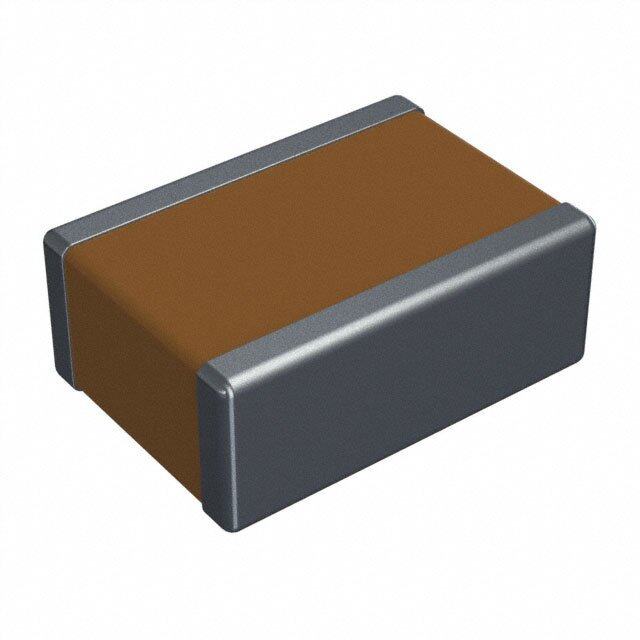
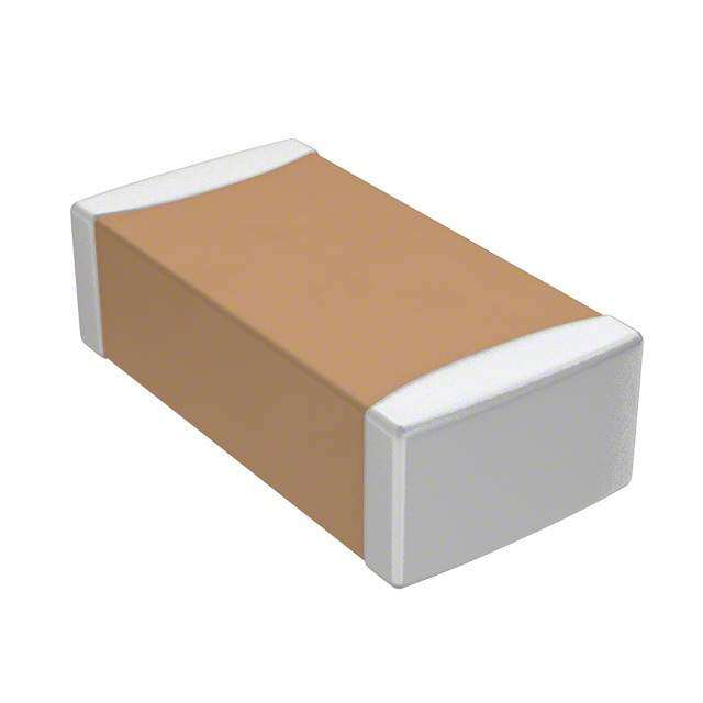
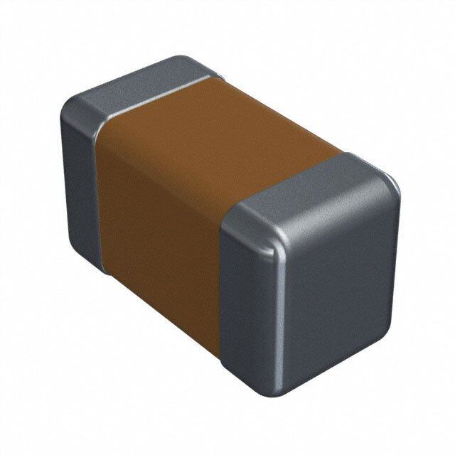
| 产品图片 | |
| rohs | 符合RoHS尚未确定供货商 / 尚未确定供货商 |
| 产品系列 | 陶瓷电容器,瓷片电容器,Murata Electronics DE2F3KY103MB3BM02FKY |
| mouser_ship_limit | 该产品可能需要其他文件才能进口到中国。 |
| 数据手册 | |
| 产品型号 | DE2F3KY103MB3BM02F |
| 产品 | Safety Ceramic Disc Capacitors |
| 产品种类 | 瓷片电容器 |
| 其它名称 | 490-9488 |
| 包装 | 散装 |
| 厚度(最大值) | - |
| 商标 | Murata Electronics |
| 外壳宽度 | 5 mm |
| 外壳直径 | 14 mm |
| 大小/尺寸 | 0.550" 直径 (14.00mm) |
| 安装类型 | 通孔 |
| 容差 | 20 % |
| 封装 | Bulk |
| 封装/外壳 | 径向,圆盘 |
| 工作温度 | -25°C ~ 85°C |
| 工作温度范围 | - 25 C to + 85 C |
| 应用 | Safety |
| 引线形式 | 成型引线 |
| 引线直径 | 0.6 mm |
| 引线间距 | 0.295"(7.50mm) |
| 引线间隔 | 7.5 mm |
| 最大工作温度 | + 85 C |
| 最小工作温度 | - 20 C |
| 标准包装 | 200 |
| 温度系数 | - 80 %, + 30 % |
| 温度系数/代码 | F |
| 特性 | 高电压 |
| 电介质 | F |
| 电压-额定 | 250VAC |
| 电压额定值 | 250 V |
| 电压额定值AC | 250 V, 300 V |
| 电容 | 0.01 uF |
| 端接类型 | Radial |
| 等级 | X1Y2 |
| 类 | X1, Y2 |
| 类型 | Safety Standard Certified Ceramic Capacitors |
| 系列 | DE |
| 高度-安装(最大值) | 0.669"(17.00mm) |


- 商务部:美国ITC正式对集成电路等产品启动337调查
- 曝三星4nm工艺存在良率问题 高通将骁龙8 Gen1或转产台积电
- 太阳诱电将投资9.5亿元在常州建新厂生产MLCC 预计2023年完工
- 英特尔发布欧洲新工厂建设计划 深化IDM 2.0 战略
- 台积电先进制程称霸业界 有大客户加持明年业绩稳了
- 达到5530亿美元!SIA预计今年全球半导体销售额将创下新高
- 英特尔拟将自动驾驶子公司Mobileye上市 估值或超500亿美元
- 三星加码芯片和SET,合并消费电子和移动部门,撤换高东真等 CEO
- 三星电子宣布重大人事变动 还合并消费电子和移动部门
- 海关总署:前11个月进口集成电路产品价值2.52万亿元 增长14.8%


PDF Datasheet 数据手册内容提取
C85E.pdf Sep.14,2018 Lead Type Disc Ceramic Capacitors (Safety Standard Certifi ed) Resin Molding SMD Type Ceramic Capacitors (Safety Standard Certifi ed)
!Note • Please read rating and !CAUTION (for storage, operating, rating, soldering, mounting and handling) in this catalog to prevent smoking and/or burning, etc. C85E.pdf • This catalog has only typical specifications. Therefore, please approve our product specifications or transact the approval sheet for product specifications before ordering. Sep.14,2018 EU RoHS Compliant • All the products in this catalog comply with EU RoHS. • EU RoHS is "the European Directive 2011/65/EU on the Restriction of the Use of Certain Hazardous Substances in Electrical and Electronic Equipment." • For more details, please refer to our web page, "Murata's Approach for EU RoHS" (https://www.murata.com/en-eu/support/ compliance/rohs).
!Note (cid:129) Please read rating and !CAUTION (for storage, operating, rating, soldering, mounting and handling) in this catalog to prevent smoking and/or burning, etc. C85E.pdf (cid:129) This catalog has only typical specifications. Therefore, please approve our product specifications or transact the approval sheet for product specifications before ordering. Sep.14,2018 1 Contents Product specifications are as of August 2018. Part Numbering p2 2 Safety Standard Certified Resin Molding SMD Type Ceramic Capacitors for General Purpose 1 Type EA (Reinforced Insulation) -Class X1, Y1- (Recommend) p5 Type EA Specifications and Test Methods p7 Type EA Complemant of Test Methods p9 3 Type EA Packing p10 Type EA !Caution p11 Type EA Notice p14 Safety Standard Certified Lead Type Disc Ceramic Capacitors for General Purpose 4 2 Type SA: AC400V (Basic Insulation) -Class X1, Y2- (Recommend) p15 3 Type RA: AC500V (Reinforced Insulation) -Class X1, Y1- (Recommend) p17 Type SA: AC400V / RA: AC500V Specifications and Test Methods p19 4 Type SA: AC250V or AC300V (Basic Insulation) -Class X1, Y2- (Recommend) p23 5 5 Type RA: AC250V or AC300V (Reinforced Insulation) -Class X1, Y1- (Recommend) p26 Type SA: AC250V or AC300V / RA: AC250V or AC300V Specifications and Test Methods p29 6 Type RB (Reinforced Insulation) -Class X1, Y1- (Recommend) p33 Type RB: X1: AC760V Specifications and Test Methods p35 7 Type KY (Basic Insulation) -Class X1, Y2- p39 6 8 Type KX New Small Size (Reinforced Insulation) -Class X1, Y1- p42 Type KY/KX Specifications and Test Methods p45 Characteristics Data (Typical Example) p49 Packaging p53 7 !Caution p55 Notice p58 Safety Standard Certified Lead Type Disc Ceramic Capacitors for Automotive 9 Type KJ -Class X1, Y2- (For Automotive Use/AC Line Filter of PHEV/EV Charger) p59 8 Type KJ Specifications and Test Methods p60 Characteristics Data (Typical Example) p64 Packaging p65 !Caution p66 Notice p69 9 Lead Type Disc Ceramic Capacitors (Safety Certified)/ Resin Molding SMD Type Ceramic Capacitors (Safety Certified) ISO9000 Certifications p70 Please check the MURATA website (https://www.murata.com/) if you cannot find a part number in this catalog.
!Note (cid:129) Please read rating and !CAUTION (for storage, operating, rating, soldering, mounting and handling) in this catalog to prevent smoking and/or burning, etc. C85E.pdf (cid:129) This catalog has only typical specifications. Therefore, please approve our product specifications or transact the approval sheet for product specifications before ordering. Sep.14,2018 o Part Numbering Safety Standard Certified Resin Molding SMD Type Ceramic Capacitors for General Purpose (Part Number) DK 1 E3 EA 102 M 86 R AH01 1 2 3 4 5 6 7 8 9 1Product ID 2Series Category 6Capacitance Tolerance Product Code Capacitance Tolerance Code Outline Contents ID K ±10% DK 1 Safety Standard IEC60384-14 ClassX1, Y1 M ±20% Certified 7Case Size 3Temperature Characteristics Code Dimensions Temperature Cap. Change Temperature 86 8.0 x 6.0mm Code Characteristics or Temp. Coeff. Range B3 B ±10% 8Packaging -25 to +85°C E3 E +20%, -55% Code Packaging 1X SL +350 to -1000ppm/°C +20 to +85°C R ø330mm Embossed Taping 4Rated Voltage/Safety Standard Certified Type 9Individual Specification Code Expressed by four figures. Code Rated Voltage X1: AC440V (r.m.s.), Y1: AC250V (r.m.s.) EA or X1: AC440V (r.m.s.), Y1: AC300V (r.m.s.) (Safety Standard Certified Type EA) 5Capacitance Expressed by three figures. The unit is pico-farad (pF). The first and second figures are significant digits, and the third figure expresses the number of zeros that follow the two numbers. 2
!Note (cid:129) Please read rating and !CAUTION (for storage, operating, rating, soldering, mounting and handling) in this catalog to prevent smoking and/or burning, etc. C85E.pdf (cid:129) This catalog has only typical specifications. Therefore, please approve our product specifications or transact the approval sheet for product specifications before ordering. Sep.14,2018 Safety Standard Certified Lead Type Disc Ceramic Capacitors for General Purpose (Part Number) DE 2 E3 KY 102 M N3 A F 1 2 3 4 5 6 7 8 9 : 1Product ID 2Series Category 6Capacitance Tolerance Product Code Capacitance Tolerance Code Outline Contents ID J ±5% 1 Safety Standard IEC60384-14 Class X1, Y1 K ±10% DE 2 Certified IEC60384-14 Class X1, Y2 M ±20% For Electrical Appliance and Material Safety Law of Japan, the first three digits (1Product ID and 2Series Category) express "Series 7Lead Style Name." Dimensions (mm) For Safety Certified Capacitors, the first three digits express product code. The fourth figure expresses certified type shown in 4Safety Code Lead Style Lead Lead Pitch of Standard Certified Type column. Spacing Diameter Components A2 5 3Temperature Characteristics A3 Vertical Crimp 7.5 ø0.6±0.05 — Long Temperature Cap. Change Temperature A4 10 Code Characteristics or Temp. Coeff. Range B2/J2 5 Vertical Crimp B3 B ±10% B3/J3 7.5 ø0.6±0.05 — Short E3 E +20%, -55% -25 to +85°C B4/J4 10 F3 F +30%, -80% N2 5 12.7 Vertical Crimp 1X SL +350 to -1000ppm/°C +20 to +85°C N3 7.5 ø0.6±0.05 15 Taping N4 10 25.4 4Rated Voltage/Safety Standard Certified Type Code Rated Voltage 8Packaging X1: AC440V (r.m.s.), Y1: AC250V (r.m.s.) Code Packaging RA or X1: AC440V (r.m.s.), Y1: AC300V (r.m.s.) A Ammo Pack Taping or X1: AC500V (r.m.s.), Y1: AC500V (r.m.s.) (Safety Standard Certified Type RA) B Bulk X1: AC760V (r.m.s.), Y1: AC500V (r.m.s.) RB (Safety Standard Certified Type RB) 9Individual Specification Code X1: AC440V (r.m.s.), Y1: AC250V (r.m.s.) For part number that cannot be identified without "Individual KX or X1: AC440V (r.m.s.), Y1: AC300V (r.m.s.) Specification," it is added at the end of part number, expressed by (Safety Standard Certified Type KX) three-digit alphanumerics. X1: AC300V (r.m.s.), Y2: AC250V (r.m.s.) SA or X1: AC300V (r.m.s.), Y2: AC300V (r.m.s.) :Halogen-free Compatible Product or X1: AC440V (r.m.s.), Y2: AC400V (r.m.s.) (Safety Standard Certified Type SA) X1: AC250V (r.m.s.), Y2: AC250V (r.m.s.) KY or X1: AC250V (r.m.s.), Y2: AC300V (r.m.s.) (Safety Standard Certified Type KY) 5Capacitance Expressed by three figures. The unit is pico-farad (pF). The first and second figures are significant digits, and the third figure expresses the number of zeros that follow the two numbers. 3
!Note (cid:129) Please read rating and !CAUTION (for storage, operating, rating, soldering, mounting and handling) in this catalog to prevent smoking and/or burning, etc. C85E.pdf (cid:129) This catalog has only typical specifications. Therefore, please approve our product specifications or transact the approval sheet for product specifications before ordering. Sep.14,2018 Safety Standard Certified Lead Type Disc Ceramic Capacitors for Automotive (Part Number) DE 6 E3 KJ 102 M N3 A 1 2 3 4 5 6 7 8 9 1Product ID 2Series Category 7Lead Style Product Dimensions (mm) Code Outline Contents ID Code Lead Style Lead Lead Pitch of DE 6 Safety Standard IEC60384-14 Class X1, Y2 Spacing Diameter Components Certified A3 Vertical Crimp — The first three digits express product code. The fourth figure expresses Long certified type shown in 4Safety Standard Certified Type column. B3 Vertical Crimp 7.5 ø0.6±0.05 — Short 3Temperature Characteristics N3 Vertical Crimp 15 Temperature Cap. Change Temperature Taping Code Characteristics or Temp. Coeff. Range B3 B ±10% 8Packaging -25 to +85°C E3 E +20%, -55% Code Packaging A Ammo Pack Taping 4Rated Voltage/Safety Standard Certified Type B Bulk Code Rated Voltage 9Individual Specification Code X1: AC440V (r.m.s.), Y2: AC300V (r.m.s.) KJ (Safety Standard Certified Type KJ) For part number that cannot be identified without "Individual Specification," it is added at the end of part number, expressed by three-digit alphanumerics. 5Capacitance Expressed by three figures. The unit is pico-farad (pF). The first and second figures are significant digits, and the third figure expresses the number of zeros that follow the two numbers. 6Capacitance Tolerance Code Capacitance Tolerance K ±10% M ±20% 4
!Note (cid:129) Please read rating and !CAUTION (for storage, operating, rating, soldering, mounting and handling) in this catalog to prevent smoking and/or burning, etc. C85E.pdf (cid:129) This catalog has only typical specifications. Therefore, please approve our product specifications or transact the approval sheet for product specifications before ordering. Sep.14,2018 Safety Standard Certified Resin Molding SMD Type Ceramic Capacitors for General Purpose 1 Type EA (Reinforced Insulation) -Class X1, Y1 SMD Type- (Recommend) 3 Features 0. 5± 2. 1. Small size and low height SMD W 2. Operating temperature range guaranteed up to 125°C. 3. Dielectric strength: AC4000V 8.0±0.5 4. Class X1/Y1 capacitors certified by ENEC (SEMKO)/UL/ L CQC/KTC T 5. Can be use with a component in appliances requiring reinforced insulation and double insulation based on 0.75±0.3 (*10) UL1492, IEC60065 and IEC60950. (in mm) L: 11.4±0.5, W: 6.0±0.5, T: 2.5 max. 6. Coated with flame-retardant halogen-free* epoxy resin The value marked with * is a reference. (conforming to UL94V-0 standard). * Cl=900ppm max., Br=900ppm max. and Cl+Br=1500ppm max. 7. Rated voltage: X1: AC440V(r.m.s.), Y1: AC250V(r.m.s.) or X1: AC440V(r.m.s.), Y1: AC300V(r.m.s.) Applications Ideal for use as Y capacitors and primary-secondary coupling on the reduction in the size and thickness of power supply equipment. Do not use these products in any automotive power train or safety equipment including battery chargers for electric vehicles and plug-in hybrids. Only Murata products clearly stipulated as "for Automotive use" on its catalog can be used for automobile applications such as power train and safety equipment. Standard Certification Rated Voltage (250Vac) Marking Rated Voltage (250Vac) Standard No. Certified No. Rated Voltage Example Item ENEC 1 Type Designation EA EN 60384-14 SE/16008-1 (SEMKO) 2 Nominal Capacitance UL UL 60384-14 E37921 250Vac(r.m.s.) ① ② (Under 100pF: Actual value, CQC IEC 60384-14 CQC16001142384 EA 102 100pF and over: 3 digit system) KTC KC 60384-14 HU03008-16007 X1 440~ 3 Company Name Code (cid:70)(cid:3)(cid:3)(cid:3)(cid:49)(cid:24)(cid:50)(cid:38)(cid:31)(cid:35)(cid:44)(cid:3)(cid:34)(cid:33)(cid:31)(cid:35)(cid:48)(cid:48)(cid:34)(cid:50)(cid:39)(cid:3)(cid:113)(cid:31)(cid:33)(cid:44)(cid:31)(cid:34)(cid:50)(cid:3)(cid:39)(cid:33)(cid:45)(cid:38)(cid:44)(cid:31)(cid:3)(cid:44)(cid:44)(cid:51)(cid:37)(cid:43)(cid:35)(cid:49)(cid:32)(cid:3)(cid:39)(cid:35)(cid:44)(cid:48)(cid:3)(cid:50)(cid:3)(cid:43)(cid:38)(cid:35)(cid:39)(cid:37)(cid:3)(cid:48)(cid:38)(cid:31)(cid:50)(cid:44)(cid:3)(cid:33)(cid:37)(cid:38)(cid:35)(cid:31)(cid:3)(cid:45)(cid:44)(cid:36)(cid:37)(cid:3)(cid:31)(cid:35)(cid:33)(cid:3)(cid:34)(cid:47)(cid:51)(cid:51)(cid:35)(cid:39)(cid:49)(cid:3)(cid:50)(cid:39)(cid:50)(cid:45)(cid:39)(cid:45)(cid:3)(cid:48)(cid:44)(cid:35)(cid:64)(cid:52)(cid:39)(cid:49)(cid:39)(cid:45)(cid:44)(cid:3)(cid:45)(cid:36)(cid:3)(cid:50)(cid:38)(cid:35)(cid:3)(cid:31)(cid:46)(cid:46)(cid:42)(cid:39)(cid:33)(cid:31)(cid:50)(cid:39)(cid:45)(cid:44) Y1 250~ 15: Made in Thailand 15 5N 4 Manufactured Date Code KTC Approval Mark ③ ④ Class Code X1Y1 Rated Voltage Mark 440~, 250~ Continued on the following page. 5
!Note (cid:129) Please read rating and !CAUTION (for storage, operating, rating, soldering, mounting and handling) in this catalog to prevent smoking and/or burning, etc. C85E.pdf (cid:129) This catalog has only typical specifications. Therefore, please approve our product specifications or transact the approval sheet for product specifications before ordering. Sep.14,2018 Continued from the preceding page. Standard Certification Rated Voltage (300Vac) Marking Rated Voltage (300Vac) Standard No. Certified No. Rated Voltage Example Item 1 ENEC EN 60384-14 SE/16008-1 1 Type Designation EA (SEMKO) 300Vac(r.m.s.) ① ② 2 Nominal Capacitance UL UL 60384-14 E37921 EA 102 (Under 100pF: Actual value, CQC IEC 60384-14 CQC16001142384 X1 440~ 100pF and over: 3 digit system) (cid:70)(cid:3)(cid:3)(cid:3)(cid:49)(cid:24)(cid:50)(cid:38)(cid:31)(cid:35)(cid:44)(cid:3)(cid:34)(cid:33)(cid:31)(cid:35)(cid:48)(cid:48)(cid:34)(cid:50)(cid:39)(cid:3)(cid:113)(cid:31)(cid:33)(cid:44)(cid:31)(cid:34)(cid:50)(cid:3)(cid:39)(cid:33)(cid:45)(cid:38)(cid:44)(cid:31)(cid:3)(cid:44)(cid:44)(cid:51)(cid:37)(cid:43)(cid:35)(cid:49)(cid:32)(cid:3)(cid:39)(cid:35)(cid:44)(cid:48)(cid:3)(cid:50)(cid:3)(cid:43)(cid:38)(cid:35)(cid:39)(cid:37)(cid:3)(cid:48)(cid:38)(cid:31)(cid:50)(cid:44)(cid:3)(cid:33)(cid:37)(cid:38)(cid:35)(cid:31)(cid:3)(cid:45)(cid:44)(cid:36)(cid:37)(cid:3)(cid:31)(cid:35)(cid:33)(cid:3)(cid:34)(cid:47)(cid:51)(cid:51)(cid:35)(cid:39)(cid:49)(cid:3)(cid:50)(cid:39)(cid:50)(cid:45)(cid:39)(cid:45)(cid:3)(cid:48)(cid:44)(cid:35)(cid:64)(cid:52)(cid:39)(cid:49)(cid:39)(cid:45)(cid:44)(cid:3)(cid:45)(cid:36)(cid:3)(cid:50)(cid:38)(cid:35)(cid:3)(cid:31)(cid:46)(cid:46)(cid:42)(cid:39)(cid:33)(cid:31)(cid:50)(cid:39)(cid:45)(cid:44) Y1 300~ 3 Company Name Code 15: Made in Thailand 15 5N 4 Manufactured Date Code Class Code X1Y1 ③ ④ Rated Voltage Mark 440~, 300~ Rated Voltage 250Vac AC Rated Temp. Body Part Number Capacitance Dimension L Dimension W Voltage Char. Thickness T DK11XEA100K86RAH01 250Vac(r.m.s.) SL 10pF±10% 11.4±0.5mm 6.0±0.5mm 2.5mm max. DK11XEA220K86RAH01 250Vac(r.m.s.) SL 22pF±10% 11.4±0.5mm 6.0±0.5mm 2.5mm max. DK11XEA470K86RAH01 250Vac(r.m.s.) SL 47pF±10% 11.4±0.5mm 6.0±0.5mm 2.5mm max. DK1B3EA101K86RAH01 250Vac(r.m.s.) B 100pF±10% 11.4±0.5mm 6.0±0.5mm 2.5mm max. DK1B3EA221K86RAH01 250Vac(r.m.s.) B 220pF±10% 11.4±0.5mm 6.0±0.5mm 2.5mm max. DK1B3EA331K86RAH01 250Vac(r.m.s.) B 330pF±10% 11.4±0.5mm 6.0±0.5mm 2.5mm max. DK1B3EA471K86RAH01 250Vac(r.m.s.) B 470pF±10% 11.4±0.5mm 6.0±0.5mm 2.5mm max. DK1B3EA681K86RAH01 250Vac(r.m.s.) B 680pF±10% 11.4±0.5mm 6.0±0.5mm 2.5mm max. DK1E3EA102M86RAH01 250Vac(r.m.s.) E 1000pF±20% 11.4±0.5mm 6.0±0.5mm 2.5mm max. DK1E3EA152M86RAH01 250Vac(r.m.s.) E 1500pF±20% 11.4±0.5mm 6.0±0.5mm 2.5mm max. Murata part numbers might be changed. Therefore, please specify only the type name (EA) and capacitance of products in the part list when it is required for applying safety standard of electric equipments. Rated Voltage 300Vac AC Rated Temp. Body Part Number Capacitance Dimension L Dimension W Voltage Char. Thickness T DK11XEA100K86RBH01 300Vac(r.m.s.) SL 10pF±10% 11.4±0.5mm 6.0±0.5mm 2.5mm max. DK11XEA220K86RBH01 300Vac(r.m.s.) SL 22pF±10% 11.4±0.5mm 6.0±0.5mm 2.5mm max. DK11XEA470K86RBH01 300Vac(r.m.s.) SL 47pF±10% 11.4±0.5mm 6.0±0.5mm 2.5mm max. DK1B3EA101K86RBH01 300Vac(r.m.s.) B 100pF±10% 11.4±0.5mm 6.0±0.5mm 2.5mm max. DK1B3EA221K86RBH01 300Vac(r.m.s.) B 220pF±10% 11.4±0.5mm 6.0±0.5mm 2.5mm max. DK1B3EA331K86RBH01 300Vac(r.m.s.) B 330pF±10% 11.4±0.5mm 6.0±0.5mm 2.5mm max. DK1B3EA471K86RBH01 300Vac(r.m.s.) B 470pF±10% 11.4±0.5mm 6.0±0.5mm 2.5mm max. DK1B3EA681K86RBH01 300Vac(r.m.s.) B 680pF±10% 11.4±0.5mm 6.0±0.5mm 2.5mm max. DK1E3EA102M86RBH01 300Vac(r.m.s.) E 1000pF±20% 11.4±0.5mm 6.0±0.5mm 2.5mm max. DK1E3EA152M86RBH01 300Vac(r.m.s.) E 1500pF±20% 11.4±0.5mm 6.0±0.5mm 2.5mm max. Murata part numbers might be changed. Therefore, please specify only the type name (EA) and capacitance of products in the part list when it is required for applying safety standard of electric equipments. 6 Continued on the following page.
!Note (cid:129) Please read rating and !CAUTION (for storage, operating, rating, soldering, mounting and handling) in this catalog to prevent smoking and/or burning, etc. C85E.pdf (cid:129) This catalog has only typical specifications. Therefore, please approve our product specifications or transact the approval sheet for product specifications before ordering. Sep.14,2018 Type EA Specifications and Test Methods 1 Operating Temperature Range: -40 to +125°C No. Item Specifications Test Method 1 Appearance No defects or abnormalities Visual Inspection. 2 Dimensions Within specified dimension Using calipers and micrometers. The capacitor shall not be damage when AC4000V(r.m.s.) is 3 Dielectric Strength No defects or abnormalities applied between the terminations for 60s. The insulation resistance shall be measured with DC500±50V within 60±5s of charging. 4 Insulation Resistance (I.R.) 6000MΩ or more The voltage should be applied to the capacitor through a resistor of 1MΩ. 5 Capacitance Within the specified tolerance Capacitance/D.F. shall be measured at 20°C with the 6 Dissipation Factor (D.F.) 0.025 max. frequency of 1±0.2kHz and a voltage of AC1±0.2V(r.m.s.). Temp. Coefficient The capacitance measurement shall be made at each step in SL: +350 to -1000 ppm/°C table. (Temp. Range: +20 to +85°C) (cid:70)(cid:20)(cid:48)(cid:35)(cid:50)(cid:48)(cid:35)(cid:31)(cid:50)(cid:43)(cid:35)(cid:44)(cid:50)(cid:3)(cid:36)(cid:45)(cid:48)(cid:3)(cid:6)(cid:65)(cid:3)(cid:9)(cid:3)(cid:33)(cid:38)(cid:31)(cid:48)(cid:64) 7 Capacitance Temperature Cap. Change Perform the heat treatment at 150+0/-10°C for 60±5min Characteristics (cid:3)(cid:3)(cid:6)(cid:66)(cid:3)(cid:53)(cid:39)(cid:50)(cid:38)(cid:39)(cid:44)(cid:3)(cid:151)(cid:123)(cid:122)(cid:139) and then let sit for 24±2h at room condition*. (cid:3)(cid:3)(cid:9)(cid:66)(cid:3)(cid:53)(cid:39)(cid:50)(cid:38)(cid:39)(cid:44)(cid:3)(cid:151)(cid:124)(cid:122)(cid:71)(cid:81)(cid:127)(cid:127)(cid:139) Step 1 2 3 4 5 (Temp. Range: -25 to +85°C) Temp. (°C) 20±2 -25±2 20±2 85±2 20±2 Appearance No marked defect Solder the capacitor to the Test Jig a (glass epoxy board) shown in "Complement of test method". Capacitance Within the specified tolerance The capacitor shall be subjected to a simple harmonic motion having a total amplitude of 1.5mm, the frequency being varied Vibration 8 uniformly between the approximate limits of 10 and 55Hz. Resistance The frequency range, from 10 to 55Hz and return to 10Hz, shall D.F. Pass the item No.6 be traversed in approximately 1min. This motion shall be applied for a period of 2h in each of 3 mutually perpendicular directions (total of 6h). Immerse the capacitor in the solution of ethanol (JIS K 8101) 75% of the terminations are to be and rosin (JIS K 5902) (25% rosin in weight proportion). 9 Solderability of Termination soldered. Immerse in solder solution for 2±0.5s. Temp. of solder: 245±5°C Appearance No marked defects Preheat the capacitor at 150 to 180°C for 90±30s. Reflow temp.: 230°C min. (max. temp.: 260°C) Capacitance Within ±10% Reflow time: 30±10s. I.R. 1000MΩ or more Reflow number of times: 4 times Soldering Let sit at room condition* for 24±2h, then measure. 10 Effect (cid:70)(cid:24)(cid:38)(cid:35)(cid:3)(cid:44)(cid:35)(cid:54)(cid:50)(cid:3)(cid:48)(cid:35)(cid:36)(cid:42)(cid:45)(cid:53)(cid:3)(cid:46)(cid:45)(cid:48)(cid:33)(cid:35)(cid:49)(cid:49)(cid:3)(cid:49)(cid:38)(cid:45)(cid:51)(cid:42)(cid:34)(cid:3)(cid:32)(cid:35)(cid:3)(cid:34)(cid:45)(cid:44)(cid:35)(cid:3)(cid:31)(cid:36)(cid:50)(cid:35)(cid:48)(cid:3)(cid:50)(cid:38)(cid:35)(cid:3)(cid:50)(cid:35)(cid:43)(cid:46)(cid:35)(cid:48)(cid:31)(cid:50)(cid:51)(cid:48)(cid:35)(cid:3) (Reflow) of the sample has dropped to room temperature. Dielectric Pass the item No.3 (cid:70)(cid:20)(cid:48)(cid:35)(cid:50)(cid:48)(cid:35)(cid:31)(cid:50)(cid:43)(cid:35)(cid:44)(cid:50)(cid:3)(cid:36)(cid:45)(cid:48)(cid:3)(cid:6)(cid:65)(cid:3)(cid:9)(cid:3)(cid:33)(cid:38)(cid:31)(cid:48)(cid:64) Strength Capacitor should be stored at 150+0/-10°C for 1h, and apply the AC4000V(r.m.s.) 60s then placed at room condition* for 24±2h before initial measurements. Solder the capacitor to the Test Jig a (glass epoxy board) shown in "Complement of test method". Then apply 10N force in the direction of the arrow. 11 Adhesive strength of No removal of the terminations or other Termination defects should occur. 10N, 10±1s (cid:11)(cid:42)(cid:31)(cid:49)(cid:49)(cid:3)(cid:9)(cid:46)(cid:45)(cid:54)(cid:55)(cid:3)(cid:6)(cid:45)(cid:31)(cid:48)(cid:34) Appearance No marked defect Fix the capacitor to the supporting Test Jig A (glass epoxy board) shown in "Complement of test method". Capacitance Within ±15% Perform the 5 cycles according to the 4 heat treatments listed Change the following table. D.F. SL: 0.025 max. Step Temp. (°C) Time (min.) (cid:6)(cid:65)(cid:3)(cid:9)(cid:66)(cid:3)0.05 max. 1 -40±3 30±3 12 Temperature I.R. 3000MΩ or more 2 Room Temp. 2 to 3 Cycle 3 125±3 30±3 4 Room Temp. 2 to 3 Let sit for 24±2h, at room condition*, then measure. Dielectric Strength Pass the item No.3 (cid:70)(cid:20)(cid:48)(cid:35)(cid:50)(cid:48)(cid:35)(cid:31)(cid:50)(cid:43)(cid:35)(cid:44)(cid:50)(cid:3)(cid:36)(cid:45)(cid:48)(cid:3)(cid:6)(cid:65)(cid:3)(cid:9)(cid:3)(cid:33)(cid:38)(cid:31)(cid:48)(cid:64) Capacitor should be stored at 150+0/-10°C for 1h, and apply the AC4000V(r.m.s.) 60s then placed at room condition* for 24±2h berore initial measurements. * "Room condition" Temperature: 15 to 35°C, Relative humidity: 45 to 75%, Atmosphere pressure: 86 to 106kPa Continued on the following page. 7
!Note (cid:129) Please read rating and !CAUTION (for storage, operating, rating, soldering, mounting and handling) in this catalog to prevent smoking and/or burning, etc. C85E.pdf (cid:129) This catalog has only typical specifications. Therefore, please approve our product specifications or transact the approval sheet for product specifications before ordering. Sep.14,2018 Type EA Specifications and Test Methods 1 Continued from the preceding page. No. Item Specifications Test Method Appearance No marked defect Sit the capacitor at 40±2°C and relative humidity 90 to 95% Capacitance Within ±20% for 500+24/-0h. Remove and let sit for 24±2h at room Change condition*, then measure. Humidity 13 SL: 0.025 max. (cid:70)(cid:20)(cid:48)(cid:35)(cid:50)(cid:48)(cid:35)(cid:31)(cid:50)(cid:43)(cid:35)(cid:44)(cid:50)(cid:3)(cid:36)(cid:45)(cid:48)(cid:3)(cid:6)(cid:65)(cid:3)(cid:9)(cid:3)(cid:33)(cid:38)(cid:31)(cid:48)(cid:64) (Steady state) D.F. B, E: 0.05 max. Capacitor should be stored at 150+0/-10°C for 1h, and apply the AC4000V(r.m.s.) 60s then placed at room condition* for I.R. 3000MΩ or more 24±2h berore initial measurements. Dielectric Strength Pass the item No.3 Appearance No marked defect Apply the rated voltage at 40±2°C and relative humidity 90 to Capacitance Within ±20% 95% for 500+24/-0h. Remove and let sit for 24±2h at room Change condition*, then measure. Humidity 14 SL: 0.025 max. (cid:70)(cid:20)(cid:48)(cid:35)(cid:50)(cid:48)(cid:35)(cid:31)(cid:50)(cid:43)(cid:35)(cid:44)(cid:50)(cid:3)(cid:36)(cid:45)(cid:48)(cid:3)(cid:6), E char. Loading D.F. B, E: 0.05 max. Capacitor should be stored at 150+0/-10°C for 1h, and apply the AC4000V(r.m.s.) 60s then placed at room condition* for I.R. 3000MΩ or more 24±2h berore initial measurements. Dielectric Strength Pass the item No.3 Appearance No marked defect Impulse Voltage test is performed. Each individual capacitor shall be subjected to a 8kV impulse Capacitance Within ±20% (the voltage value means zero to peak) for 3 times. Then the Change capacitors are applied to life test. I.R. 3000MΩ or more 100 (%) 90 Front time (T1) =1.2μs=1.67T Time to half-value (T2) =50μs 50 30 0 t T T1 15 Life T2 Apply voltage as Table for 1000h at 125+2/-0°C, relative humidity 50% max. Dielectric Strength Pass the item No.3 Applied Voltage AC550V(r.m.s.), except that once each hour the voltage is increased to AC1000V(r.m.s.) for 0.1s. Remove and let sit for 24±2h at room condition*, then measure. (cid:70)(cid:20)(cid:48)(cid:35)(cid:50)(cid:48)(cid:35)(cid:31)(cid:50)(cid:43)(cid:35)(cid:44)(cid:50)(cid:3)(cid:36)(cid:45)(cid:48)(cid:3)(cid:6)(cid:65)(cid:3)(cid:9)(cid:3)(cid:33)(cid:38)(cid:31)(cid:48)(cid:64) Capacitor should be stored at 150+0/-10°C for 1h, and apply the AC4000V(r.m.s.) 60s then placed at room condition* for 24±2h berore initial measurements. The capacitor under test shall be held in the flame in the position which best promotes burning. Each specimen shall only be exposed once to the flame. Time of exposure to flame: 30s. Length of flame : 12±1mm Gas burner : Length 35mm min. Inside Dia. 0.5±0.1mm Outside Dia. 0.9mm max. The burning time should not exceeded Gas : Butane gas Purity 95% min. 16 Passive Flammability the time 30s. The tissue paper should not ignite. Test Specimen Approximately 8mm m burner flame 5m 45° 0± 0 2 Tissue Paper Wood board of approximately 10mm in thickness * "Room condition" Temperature: 15 to 35°C, Relative humidity: 45 to 75%, Atmosphere pressure: 86 to 106kPa Continued on the following page. 8
!Note (cid:129) Please read rating and !CAUTION (for storage, operating, rating, soldering, mounting and handling) in this catalog to prevent smoking and/or burning, etc. C85E.pdf (cid:129) This catalog has only typical specifications. Therefore, please approve our product specifications or transact the approval sheet for product specifications before ordering. Sep.14,2018 Type EA Specifications and Test Methods Continued from the preceding page. 1 No. Item Specifications Test Method The capacitor shall be individually wrapped in at least one but more than two complete layers of cheesecloth. The capacitor shall be subjected to 20 discharges. The interval between successive discharges should be 5s. The UAC shall be maintained for 2min after the last discharge. S(cid:123) F L(cid:123) L2 R C(cid:123) C2 C3 Cx Ct Ut Tr S2 UAC L3 L(cid:126) Oscilloscope 17 Active Flammability The cheesecloth should not be on fire. C(cid:123)(cid:65)(cid:124)(cid:3) (cid:66)(cid:3)(cid:123)(cid:163)(cid:10)(cid:151)(cid:123)(cid:122)(cid:139)(cid:3) (cid:7)3(cid:3) (cid:66)(cid:3)(cid:122)(cid:64)(cid:122)(cid:125)(cid:125)(cid:163)(cid:10)(cid:151)(cid:127)(cid:139)(cid:3)(cid:123)(cid:122)(cid:41)(cid:26) L(cid:123)(cid:3)(cid:50)(cid:45)(cid:3)(cid:126)(cid:3)(cid:66)(cid:3)(cid:123)(cid:64)(cid:127)(cid:43)(cid:12)(cid:151)(cid:124)(cid:122)(cid:139)(cid:3)(cid:123)(cid:128)(cid:5)(cid:3)(cid:22)(cid:45)(cid:34)(cid:3)(cid:33)(cid:45)(cid:48)(cid:35)(cid:3)(cid:33)(cid:38)(cid:45)(cid:41)(cid:35) Ct : 3(cid:163)(cid:10)(cid:151)(cid:127)(cid:139)(cid:3)(cid:123)(cid:122)(cid:41)(cid:52) R(cid:3) (cid:66)(cid:3)(cid:123)(cid:122)(cid:122)Ω(cid:151)(cid:124)(cid:139) Cx : Capacitor specimens UAC : UR(cid:151)(cid:127)(cid:139) F : (cid:10)(cid:51)(cid:49)(cid:35)(cid:65)(cid:3)(cid:48)(cid:31)(cid:50)(cid:35)(cid:34)(cid:3)(cid:123)(cid:128)(cid:5) UR : Rated Voltage Ut : Voltage impressed on the tank capacitor Ct Ux 5kV time Complement of Test Method Test Jig The test jig should be Jig A as described in “Specifications and Test Methods”. The specimen should be soldered by the conditions as described below. Soldering Method: Reflow soldering Solder: Sn-3.0Ag-0.5Cu Test Jig A (cid:131)(cid:64)(cid:126) (cid:127)(cid:64)(cid:126) (cid:125)(cid:64)(cid:128) 0.5 0 (cid:122) 2. (cid:123)(cid:64) 2 2. (cid:129)(cid:64)(cid:126) 8.0 (cid:123)(cid:131)(cid:64)(cid:126) Solder resist Copper foil (in mm) Test Jig (cid:70)(cid:17)(cid:31)(cid:50)(cid:35)(cid:48)(cid:39)(cid:31)(cid:42)(cid:66)(cid:3)(cid:11)(cid:42)(cid:31)(cid:49)(cid:49)(cid:3)(cid:9)(cid:46)(cid:45)(cid:54)(cid:55)(cid:3)(cid:6)(cid:45)(cid:31)(cid:48)(cid:34) (cid:70)(cid:24)(cid:38)(cid:39)(cid:33)(cid:41)(cid:44)(cid:35)(cid:49)(cid:49)(cid:66)(cid:3)(cid:123)(cid:64)(cid:128)(cid:43)(cid:43) (cid:70)(cid:24)(cid:38)(cid:39)(cid:33)(cid:41)(cid:44)(cid:35)(cid:49)(cid:49)(cid:3)(cid:45)(cid:36)(cid:3)(cid:33)(cid:45)(cid:46)(cid:46)(cid:35)(cid:48)(cid:3)(cid:36)(cid:45)(cid:39)(cid:42)(cid:66)(cid:3)(cid:122)(cid:64)(cid:122)(cid:125)(cid:127)(cid:43)(cid:43) 9
!Note (cid:129) Please read rating and !CAUTION (for storage, operating, rating, soldering, mounting and handling) in this catalog to prevent smoking and/or burning, etc. C85E.pdf (cid:129) This catalog has only typical specifications. Therefore, please approve our product specifications or transact the approval sheet for product specifications before ordering. Sep.14,2018 Type EA Packing 1 Packing 1. Dimension of Tape 2.0+/-0.1 4.0+/-0.1 ø1.5+0.1/-0 1 8.0+/-0.1 0. 5+/- 0.4+/-0.1 7 1. 1 0. B 11.5+/- +/-0.3 A 24 4.0 max. A×B=12.0×7.0 (typ.) (in mm) 2. Dimension of Reel 29.4±1.0 2.0±0.5 0 1. ø21.0±0.8 ± 0 8 0 2. ± 0 3 ø13.0±0.2 3 25.4±1.0 (in mm) (1) Part of the leader and part of the empty tape shall be attached to the end of the tape as follows. Vacant section: 160 min. Capacitor mounting unit Vacant section 190 min. 210 min. Direction of feed (in mm) (2) The top tape or cover tape and base tape are not attached at the end of the tape for a minimum of 2 pitches. (3) Missing capacitors number within 0.1% of the number per reel or 1pc, whichever is greater, and not continuous. (4) The top tape or cover tape and bottom tape shall not protrude beyond the edges of the tape and shall not cover sprocket holes. (5) Cumulative tolerance of sprocket holes, 10 pitches: ±0.3mm. (6) Peeling off force: 0.1 to 0.6N in the direction shown on the follows. 165 to 180° Top Tape or Cover Tape Base Tape Minimum Quantity (Order in Sets Only) [Taping] (pcs./Ammo Pack) Packing Qty Type EA 2,500 10
!Note (cid:129) Please read rating and !CAUTION (for storage, operating, rating, soldering, mounting and handling) in this catalog to prevent smoking and/or burning, etc. C85E.pdf (cid:129) This catalog has only typical specifications. Therefore, please approve our product specifications or transact the approval sheet for product specifications before ordering. Sep.14,2018 Type EA !Caution 1 !Caution (Rating) 1. Operating Voltage When DC-rated capacitors are to be used in AC or ripple current circuits, be sure to maintain the Vp-p value of the applied voltage or the Vo-p that contains DC bias within the rated voltage range. When the voltage is applied to the circuit, starting or stopping may generate irregular voltage for a transit period because of resonance or switching. Be sure to use a capacitor with a rated voltage range that includes these irregular voltages. Voltage DC Voltage DC+AC Voltage AC Voltage Pulse Voltage (1) Pulse Voltage (2) Positional V0-p V0-p Vp-p Vp-p Vp-p Measurement 2. Operating Temperature and Self-generated Heat (Apply to B/E/F Char.) Keep the surface temperature of a capacitor below the upper limit of its rated operating temperature range. Be sure to take into account the heat generated by the capacitor itself. When the capacitor is used in a high- frequency current, pulse current or similar current, it may have self-generated heat due to dielectric loss. Applied voltage load should be such that self-generated heat is within 20°C under the condition where the capacitor is subjected to an atmospheric temperature of 25°C. When measuring, use a thermocouple of small thermal capacity-K of ø0.1mm under conditions where the capacitor is not affected by radiant heat from other components or wind from surroundings. Excessive heat may lead to deterioration of the capacitor's characteristics and reliability. (Never attempt to perform measurement with the cooling fan running. Otherwise, accurate measurement cannot be ensured.) 3. Test Condition for Withstanding Voltage (1) Test Equipment Test equipment for AC withstanding voltage should be used with the performance of the wave similar to 50/60Hz sine wave. If the distorted sine wave or overload exceeding the specified voltage value is applied, a defect may be caused. Continued on the following page. 11
!Note (cid:129) Please read rating and !CAUTION (for storage, operating, rating, soldering, mounting and handling) in this catalog to prevent smoking and/or burning, etc. C85E.pdf (cid:129) This catalog has only typical specifications. Therefore, please approve our product specifications or transact the approval sheet for product specifications before ordering. Sep.14,2018 Type EA !Caution 1 Continued from the preceding page. (2) Voltage Applied Method When the withstanding voltage is applied, the capacitor's lead or terminal should be firmly connected to the output Voltage sine wave of the withstanding voltage test equipment, and then the voltage should be raised from near zero to the test 0V voltage. zero cross If the test voltage without the raise from near zero voltage would be applied directly to capacitor, test voltage should be applied with the zero cross.* At the end of the test time, the test voltage should be reduced to near zero, and then capacitor's lead or terminal should be taken off the output of the withstanding voltage test equipment. If the test voltage without the raise from near zero voltage would be applied directly to capacitor, the surge voltage may rise, and therefore, a defect may be caused. *ZERO CROSS is the point where voltage sine wave passes 0V. See the figure at right. 4. Fail-Safe When the capacitor is broken, failure may result in a short circuit. Be sure to provide an appropriate fail-safe function like a fuse on your product if failure could result in an electric shock, fire or fuming. FAILURE TO FOLLOW THE ABOVE CAUTIONS MAY RESULT, WORST CASE, IN A SHORT CIRCUIT AND CAUSE FUMING OR PARTIAL DISPERSION WHEN THE PRODUCT IS USED. 12
!Note (cid:129) Please read rating and !CAUTION (for storage, operating, rating, soldering, mounting and handling) in this catalog to prevent smoking and/or burning, etc. C85E.pdf (cid:129) This catalog has only typical specifications. Therefore, please approve our product specifications or transact the approval sheet for product specifications before ordering. Sep.14,2018 Type EA !Caution 1 !Caution (Storage and Operating Condition) Operating and Storage Environment Solder the enclosed capacitors within 168 hours after The insulation coating of capacitors does not form a perfect opening the moisture-proof package. seal; therefore, do not use or store capacitors in a corrosive After opening, store the capacitors in moisture-proof atmosphere, especially where chloride gas, sulfide gas, acid, package with a desiccant and HIC card and keep the alkali, salt or the like are present. And avoid exposure to described condition. moisture. Before cleaning, bonding, or molding this product, verify that these processes do not affect product quality In case the storage period has been exceeded 6 months by testing the performance of a cleaned, bonded or molded or the indicator color of a enclosed HIC card has changed product in the intended equipment. when the package has been opened, perform baking This one is MSL 3 product. So, in order to avoid the (60°C x 168h) before soldering. absorption of moisture, capacitors are packed in moisture- proof envelope. FAILURE TO FOLLOW THE ABOVE CAUTIONS MAY Store the capacitors in the following conditions at all times, RESULT, WORST CASE, IN A SHORT CIRCUIT and use within 6 months after delivered. AND CAUSE FUMING OR PARTIAL DISPERSION Temperature: 10 to 30°C. WHEN THE PRODUCT IS USED. Humidity: 60% max. !Caution (Soldering and Mounting) 1. VIBRATION AND IMPACT Do not expose a capacitor or its leads to excessive shock SSttaannddaarrdd CCoonnddiittiioonnss ffoorr RReeffllooww SSoollddeerriinngg or vibration during use. TTeemmppeerraattuurree ((°°CC)) 2. SOLDERING (1) Reflow Soldering SSoollddeerriinngg 260°°CC When soldering capacitor, it should be performed in GGrraadduuaall 230°°CC CCoooolliinngg following conditions. 170°°CC 150°°CC Soldering temperature: 230 to 260°C 130°°CC PPrreehheeaattiinngg Soldering time: 10 to 30s. Preheating temperature: 170°C max. (2) Flow Soldering TTiimmee When soldering capacitor, it should be performed in 6600 -- 112200 ss 1100 -- 3300 ss following conditions. Soldering temperature: 260°C max. Soldering time: 5s max. by testing the performance of the bonded, molded or Preheating temperature: 120°C max. coated product in the intended equipment. Preheating time: 60s max. In case of the amount of applications, dryness / hardening (3) Soldering Iron conditions of adhesives and molding resins containing When soldering this product to a PCB/PWB, do not organic solvents (ethyl acetate, methyl ethyl ketone, exceed the solder heat resistance specification of the toluene, etc.) are unsuitable, the outer coating resin of a capacitor. Subjecting this product to excessive heating capacitor is damaged by the organic solvents and it may could melt the internal junction solder and may result result, worst case, in a short circuit. in thermal shocks that can crack the ceramic element. The variation in thickness of adhesive, molding resin or When soldering capacitor with a soldering iron, it should coating may cause a outer coating resin cracking and/or be performed in following conditions. ceramic element cracking of a capacitor in a temperature Temperature of iron-tip: 400°C max. cycling. Soldering iron wattage: 50W max. Soldering time: 3.5s max. FAILURE TO FOLLOW THE ABOVE CAUTIONS MAY 3. BONDING, RESIN MOLDING AND COATING RESULT, WORST CASE, IN A SHORT CIRCUIT Before bonding, molding or coating this product, verify AND CAUSE FUMING OR PARTIAL DISPERSION that these processes do not affect the quality of capacitor WHEN THE PRODUCT IS USED. 13
!Note (cid:129) Please read rating and !CAUTION (for storage, operating, rating, soldering, mounting and handling) in this catalog to prevent smoking and/or burning, etc. C85E.pdf (cid:129) This catalog has only typical specifications. Therefore, please approve our product specifications or transact the approval sheet for product specifications before ordering. Sep.14,2018 Type EA !Caution/Notice 1 !Caution (Handling) VIBRATION AND IMPACT Do not expose a capacitor or its leads to excessive shock or FAILURE TO FOLLOW THE ABOVE CAUTIONS MAY vibration during use. RESULT, WORST CASE, IN A SHORT CIRCUIT AND CAUSE FUMING OR PARTIAL DISPERSION WHEN THE PRODUCT IS USED. Notice (Soldering and Mounting) CLEANING (ULTRASONIC CLEANING) To perform ultrasonic cleaning, observe the following conditions. Rinse bath capacity: Output of 20 watts per liter or less. Rinsing time: 5min maximum. Do not vibrate the PCB/PWB directly. Excessive ultrasonic cleaning may lead to fatigue destruction of the terminals. Notice (Rating) 1. CAPACITANCE CHANGE OF CAPACITORS 2. PERFORMANCE CHECK BY EQUIPMENT (1) Class 1 capacitors Before using a capacitor, check that there is no problem in Capacitance might change a little depending on a the equipment's performance and the specifications. surrounding temperature or an applied voltage. Generally speaking, Class 2 ceramic capacitors have voltage Please contact us if you use for the strict time constant dependence characteristics and temperature dependence circuit. characteristics in capacitance. (2) Class 2 capacitors So, the capacitance value may change depending on the Class 2 capacitors like temperature characteristic B, E operating condition in a equipment. and F have an aging characteristic, whereby the capacitor Therefore, be sure to confirm the apparatus performance continually decreases its capacitance slightly if the of receiving influence in a capacitance value change of a capacitor leaves for a long time. capacitor, such as leakage current and noise suppression Moreover, capacitance might change greatly depending characteristic. on a surrounding temperature or an applied voltage. Moreover, check the surge-proof ability of a capacitor in So, it is not likely to be able to use for the time constant the equipment, if needed, because the surge voltage may circuit. exceed specific value by the inductance of the circuit. Please contact us if you need a detail information. 14
!Note (cid:129) Please read rating and !CAUTION (for storage, operating, rating, soldering, mounting and handling) in this catalog to prevent smoking and/or burning, etc. C85E.pdf (cid:129) This catalog has only typical specifications. Therefore, please approve our product specifications or transact the approval sheet for product specifications before ordering. Sep.14,2018 Safety Standard Certified Lead Type Disc Ceramic Capacitors for General Purpose Type SA: AC400V (Basic Insulation) -Class X1, Y2- (Recommend) D max. T max. Features 2 1. Impulse voltage guaranteed 8kV0-p. 2. Operating temperature range guaranteed up to 125°C. 3. Dielectric strength: AC2600V e 0 max. 3. 4. Class X1/Y2 capacitors certified by ENEC(VDE)/UL/CQC. F±1.0 min. 5. Coated with flame-retardant halogen-free* epoxy resin 0 5. 2 (conforming to UL94V-0 standard). ød * Cl=900ppm max., Br=900ppm max. and (in mm) [Bulk] Cl+Br=1500ppm max. Vertical Crimp Long (A3) Lead Code Coating Extension e ød 6. Taping available for automatic insertion. A3 Up to the end of crimp 0.6±0.05 7. Rated Voltage: X1: AC440V(r.m.s.), Y2: AC400V(r.m.s.) Applications D max. T max. Ideal for use as X/Y capacitors for AC line filters and primary-secondary coupling on switching power supplies and AC adapters. e max. 05 3.0 1.0. Do not use these products in any automotive 3.5± ød power train or safety equipment including battery F±0.8 chargers for electric vehicles and plug-in hybrids. (in mm) Only Murata products clearly stipulated as [Bulk] "for Automotive use" on its catalog can be used Vertical Crimp Short (J3) Lead Code Coating Extension e ød J3 Up to the end of crimp 0.6±0.05 for automobile applications such as power train and safety equipment. Standard Certification Marking Standard No. Certified No. Rated Voltage Example Item ENEC 1 Type Designation SA EN 60384-14 40042990 (VDE) 400Vac(r.m.s.) 2 2 Nominal Capacitance UL UL 60384-14 E37921 (Under 100pF: Actual value, SA103M CQC IEC 60384-14 CQC15001137840 1 3 100pF and over: 3 digit system) X1 440~ (cid:70)(cid:3)(cid:24)(cid:38)(cid:35)(cid:3)(cid:33)(cid:35)(cid:48)(cid:50)(cid:39)(cid:113)(cid:33)(cid:31)(cid:50)(cid:39)(cid:45)(cid:44)(cid:3)(cid:44)(cid:51)(cid:43)(cid:32)(cid:35)(cid:48)(cid:3)(cid:43)(cid:39)(cid:37)(cid:38)(cid:50)(cid:3)(cid:33)(cid:38)(cid:31)(cid:44)(cid:37)(cid:35)(cid:3)(cid:34)(cid:51)(cid:35)(cid:3)(cid:50)(cid:45)(cid:3)(cid:48)(cid:35)(cid:52)(cid:39)(cid:49)(cid:39)(cid:45)(cid:44)(cid:3)(cid:45)(cid:36)(cid:3)(cid:50)(cid:38)(cid:35)(cid:3)(cid:31)(cid:46)(cid:46)(cid:42)(cid:39)(cid:33)(cid:31)(cid:50)(cid:39)(cid:45)(cid:44) 3 Capacitance Tolerance (cid:3)(cid:3)(cid:49)(cid:50)(cid:31)(cid:44)(cid:34)(cid:31)(cid:48)(cid:34)(cid:3)(cid:31)(cid:44)(cid:34)(cid:3)(cid:33)(cid:38)(cid:31)(cid:44)(cid:37)(cid:35)(cid:49)(cid:3)(cid:39)(cid:44)(cid:3)(cid:50)(cid:38)(cid:35)(cid:3)(cid:48)(cid:31)(cid:44)(cid:37)(cid:35)(cid:3)(cid:45)(cid:36)(cid:3)(cid:31)(cid:33)(cid:47)(cid:51)(cid:39)(cid:49)(cid:39)(cid:50)(cid:39)(cid:45)(cid:44)(cid:64) Y2 400~ 4 Company Name Code 5 5D 15 4 15: Made in Thailand 5 Manufactured Date Code Class Code X1Y2 Rated Voltage Mark 440~, 400~ 15
!Note (cid:129) Please read rating and !CAUTION (for storage, operating, rating, soldering, mounting and handling) in this catalog to prevent smoking and/or burning, etc. C85E.pdf (cid:129) This catalog has only typical specifications. Therefore, please approve our product specifications or transact the approval sheet for product specifications before ordering. Sep.14,2018 Rated Voltage 400Vac AC Rated Temp. Body Lead Body Lead Lead Lead Part Number Capacitance Spacing F Package Package Package Voltage Char. Dia. D (mm) Thickness T Long Bulk Short Bulk Taping DE21XSA100KpppY02F 400Vac(r.m.s.) SL 10pF±10% 7.0mm max. 7.5 5.0mm max. A3B J3B N3A DE21XSA150KpppY02F 400Vac(r.m.s.) SL 15pF±10% 6.0mm max. 7.5 6.0mm max. A3B J3B N3A DE21XSA220KpppY02F 400Vac(r.m.s.) SL 22pF±10% 6.0mm max. 7.5 5.0mm max. A3B J3B N3A DE21XSA330KpppY02F 400Vac(r.m.s.) SL 33pF±10% 7.0mm max. 7.5 5.0mm max. A3B J3B N3A 2 DE21XSA470KpppY02F 400Vac(r.m.s.) SL 47pF±10% 7.0mm max. 7.5 5.0mm max. A3B J3B N3A DE21XSA680KpppY02F 400Vac(r.m.s.) SL 68pF±10% 9.0mm max. 7.5 5.0mm max. A3B J3B N3A DE2B3SA101KpppY02F 400Vac(r.m.s.) B 100pF±10% 6.0mm max. 7.5 5.0mm max. A3B J3B N3A DE2B3SA151KpppY02F 400Vac(r.m.s.) B 150pF±10% 6.0mm max. 7.5 5.0mm max. A3B J3B N3A DE2B3SA221KpppY02F 400Vac(r.m.s.) B 220pF±10% 6.0mm max. 7.5 6.0mm max. A3B J3B N3A DE2B3SA331KpppY02F 400Vac(r.m.s.) B 330pF±10% 6.0mm max. 7.5 5.0mm max. A3B J3B N3A DE2B3SA471KpppY02F 400Vac(r.m.s.) B 470pF±10% 7.0mm max. 7.5 5.0mm max. A3B J3B N3A DE2B3SA681KpppY02F 400Vac(r.m.s.) B 680pF±10% 8.0mm max. 7.5 5.0mm max. A3B J3B N3A DE2E3SA102MpppY02F 400Vac(r.m.s.) E 1000pF±20% 7.0mm max. 7.5 5.0mm max. A3B J3B N3A DE2E3SA152MpppY02F 400Vac(r.m.s.) E 1500pF±20% 8.0mm max. 7.5 5.0mm max. A3B J3B N3A DE2E3SA222MpppY02F 400Vac(r.m.s.) E 2200pF±20% 9.0mm max. 7.5 5.0mm max. A3B J3B N3A DE2E3SA332MpppY02F 400Vac(r.m.s.) E 3300pF±20% 12.0mm max. 7.5 5.0mm max. A3B J3B N3A DE2E3SA472MpppY02F 400Vac(r.m.s.) E 4700pF±20% 13.0mm max. 7.5 5.0mm max. A3B J3B N3A DE2E3SA103MpppY02F 400Vac(r.m.s.) E 10000pF±20% 17.0mm max. 7.5 6.0mm max. A3B J3B N7A Three blank columns are filled with the lead and packaging codes. Please refer to the 3 columns on the right for the appropriate codes. Individual specification code "Y02F" express "simplicity marking and guarantee of dielectric strength between lead wires: AC2600V." Murata part numbers might be changed depending on lead code or any other chagnes. Therefore, please specify only the type name (SA) and capacitance of products in the part list when it is required for applying safety standard of electric equipments. 16
!Note (cid:129) Please read rating and !CAUTION (for storage, operating, rating, soldering, mounting and handling) in this catalog to prevent smoking and/or burning, etc. C85E.pdf (cid:129) This catalog has only typical specifications. Therefore, please approve our product specifications or transact the approval sheet for product specifications before ordering. Sep.14,2018 Safety Standard Certified Lead Type Disc Ceramic Capacitors for General Purpose Type RA: AC500V (Reinforced Insulation) -Class X1, Y1- (Recommend) D max. T max. Features 1. Impulse voltage guaranteed 12kV0-p. 2. Operating temperature range guaranteed up to 125°C. 3. Dielectric strength: AC4000V e 0 max. 3. 4. Class X1/Y1 capacitors certified by ENEC(VDE)/UL/CQC. 5. Can be use with a component in appliances requiring F±1.0 min. 0 5. reinforced insulation and double insulation based on 2 ød UL1492, IEC60065 and IEC60950. 3 (in mm) [Bulk] 6. Coated with flame-retardant halogen-free* epoxy resin Vertical Crimp Long (A4) Lead Code Coating Extension e ød (conforming to UL94V-0 standard). A4 Up to the end of crimp 0.6±0.05 * Cl=900ppm max., Br=900ppm max. and Cl+Br=1500ppm max. 7. Taping available for automatic insertion. D max. T max. 8. Rated Voltage: X1: AC500V(r.m.s.), Y1: AC500V(r.m.s.) Applications e max. Ideal for use as X/Y capacitors for AC line filters 05 3.0 1.0. and primary-secondary coupling on switching power 3.5± ød supplies and AC adapters. F±0.8 (in mm) Do not use these products in any automotive [Bulk] power train or safety equipment including battery Vertical Crimp Short (J4) Lead Code Coating Extension e ød J4 Up to the end of crimp 0.6±0.05 chargers for electric vehicles and plug-in hybrids. Only Murata products clearly stipulated as "for Automotive use" on its catalog can be used for automobile applications such as power train and safety equipment. Standard Certification Marking Standard No. Certified No. Rated Voltage Example Item ENEC 1 Type Designation RA EN 60384-14 40043033 (VDE) 500Vac(r.m.s.) 2 2 Nominal Capacitance UL UL 60384-14 E37921 (Under 100pF: Actual value, RA 472M CQC IEC 60384-14 CQC16001138225 1 3 100pF and over: 3 digit system) X1 500~ (cid:70)(cid:3)(cid:24)(cid:38)(cid:35)(cid:3)(cid:33)(cid:35)(cid:48)(cid:50)(cid:39)(cid:113)(cid:33)(cid:31)(cid:50)(cid:39)(cid:45)(cid:44)(cid:3)(cid:44)(cid:51)(cid:43)(cid:32)(cid:35)(cid:48)(cid:3)(cid:43)(cid:39)(cid:37)(cid:38)(cid:50)(cid:3)(cid:33)(cid:38)(cid:31)(cid:44)(cid:37)(cid:35)(cid:3)(cid:34)(cid:51)(cid:35)(cid:3)(cid:50)(cid:45)(cid:3)(cid:48)(cid:35)(cid:52)(cid:39)(cid:49)(cid:39)(cid:45)(cid:44)(cid:3)(cid:45)(cid:36)(cid:3)(cid:50)(cid:38)(cid:35)(cid:3)(cid:31)(cid:46)(cid:46)(cid:42)(cid:39)(cid:33)(cid:31)(cid:50)(cid:39)(cid:45)(cid:44) 3 Capacitance Tolerance (cid:3)(cid:3)(cid:49)(cid:50)(cid:31)(cid:44)(cid:34)(cid:31)(cid:48)(cid:34)(cid:3)(cid:31)(cid:44)(cid:34)(cid:3)(cid:33)(cid:38)(cid:31)(cid:44)(cid:37)(cid:35)(cid:49)(cid:3)(cid:39)(cid:44)(cid:3)(cid:50)(cid:38)(cid:35)(cid:3)(cid:48)(cid:31)(cid:44)(cid:37)(cid:35)(cid:3)(cid:45)(cid:36)(cid:3)(cid:31)(cid:33)(cid:47)(cid:51)(cid:39)(cid:49)(cid:39)(cid:50)(cid:39)(cid:45)(cid:44)(cid:64) Y1 500~ 4 Company Name Code 5 5D 15 4 15: Made in Thailand 5 Manufactured Date Code Class Code X1Y1 Rated Voltage Mark 500~ 17
!Note (cid:129) Please read rating and !CAUTION (for storage, operating, rating, soldering, mounting and handling) in this catalog to prevent smoking and/or burning, etc. C85E.pdf (cid:129) This catalog has only typical specifications. Therefore, please approve our product specifications or transact the approval sheet for product specifications before ordering. Sep.14,2018 Rated Voltage 500Vac AC Rated Temp. Body Lead Body Lead Lead Lead Part Number Capacitance Spacing F Package Package Package Voltage Char. Dia. D (mm) Thickness T Long Bulk Short Bulk Taping DE11XRA100KpppQ01F 500Vac(r.m.s.) SL 10pF±10% 8.0mm max. 10.0 5.0mm max. A4B J4B N4A DE11XRA150KpppQ01F 500Vac(r.m.s.) SL 15pF±10% 6.0mm max. 10.0 6.0mm max. A4B J4B N4A DE11XRA220KpppQ01F 500Vac(r.m.s.) SL 22pF±10% 6.0mm max. 10.0 5.0mm max. A4B J4B N4A DE11XRA330KpppQ01F 500Vac(r.m.s.) SL 33pF±10% 7.0mm max. 10.0 5.0mm max. A4B J4B N4A DE11XRA470KpppQ01F 500Vac(r.m.s.) SL 47pF±10% 8.0mm max. 10.0 5.0mm max. A4B J4B N4A DE11XRA680KpppQ01F 500Vac(r.m.s.) SL 68pF±10% 9.0mm max. 10.0 5.0mm max. A4B J4B N4A DE1B3RA101KpppQ01F 500Vac(r.m.s.) B 100pF±10% 6.0mm max. 10.0 5.0mm max. A4B J4B N4A DE1B3RA151KpppQ01F 500Vac(r.m.s.) B 150pF±10% 8.0mm max. 10.0 5.0mm max. A4B J4B N4A DE1B3RA221KpppQ01F 500Vac(r.m.s.) B 220pF±10% 6.0mm max. 10.0 6.0mm max. A4B J4B N4A DE1B3RA331KpppQ01F 500Vac(r.m.s.) B 330pF±10% 7.0mm max. 10.0 6.0mm max. A4B J4B N4A 3 DE1B3RA471KpppQ01F 500Vac(r.m.s.) B 470pF±10% 8.0mm max. 10.0 6.0mm max. A4B J4B N4A DE1B3RA681KpppQ01F 500Vac(r.m.s.) B 680pF±10% 9.0mm max. 10.0 6.0mm max. A4B J4B N4A DE1E3RA102MpppQ01F 500Vac(r.m.s.) E 1000pF±20% 8.0mm max. 10.0 6.0mm max. A4B J4B N4A DE1E3RA152MpppQ01F 500Vac(r.m.s.) E 1500pF±20% 9.0mm max. 10.0 6.0mm max. A4B J4B N4A DE1E3RA222MpppQ01F 500Vac(r.m.s.) E 2200pF±20% 11.0mm max. 10.0 6.0mm max. A4B J4B N4A DE1E3RA332MpppQ01F 500Vac(r.m.s.) E 3300pF±20% 13.0mm max. 10.0 6.0mm max. A4B J4B N4A DE1E3RA472MpppQ01F 500Vac(r.m.s.) E 4700pF±20% 14.0mm max. 10.0 6.0mm max. A4B J4B N4A Three blank columns are filled with the lead and packaging codes. Please refer to the 3 columns on the right for the appropriate codes. Murata part numbers might be changed depending on lead code or any other chagnes. Therefore, please specify only the type name (RA) and capacitance of products in the part list when it is required for applying safety standard of electric equipments. 18
!Note (cid:129) Please read rating and !CAUTION (for storage, operating, rating, soldering, mounting and handling) in this catalog to prevent smoking and/or burning, etc. C85E.pdf (cid:129) This catalog has only typical specifications. Therefore, please approve our product specifications or transact the approval sheet for product specifications before ordering. Sep.14,2018 Type SA: AC400V / RA: AC500V Specifications and Test Methods Operating Temperature Range: -40 to +125°C No. Item Specifications Test Method The capacitor should be visually inspected for evidence of No visible defect, and dimensions are within 1 Appearance and Dimensions defect. specified range. Dimensions should be measured with slide calipers. 2 Marking To be easily legible The capacitor should be visually inspected. 3 Capacitance Within specified tolerance The capacitance, dissipation factor should be measured at 4 Dissipation Factor (D.F.) 2.5% max. 20˚C with 1±0.1kHz and AC1±0.2V max. The insulation resistance should be measured with DC500±50V within 60±5s of charging. 5 Insulation Resistance (I.R.) 10000MΩ min. The voltage should be applied to the capacitor through a resistor of 1MΩ. The capacitor should not be damaged when the test voltages from Table 1 are applied between the lead wires for 60s. Between Lead <Table 1> No failure Wires Type Test Voltage SA AC2600V(r.m.s.) ‹50/60Hz› RA AC4000V(r.m.s.) ‹50/60Hz› First, the terminals of the capacitor about should be connected together. Then, 3 to 4mm as shown in the figure at right, a metal (in case of Type RA: 6 Dielectric ftohiel sbhooduyl do fb teh cel ocsaeplayc witroarp tpoe tdh aer ound Metal 3 to 6mm) Strength Foil distance of about 3 to 4mm (in case of Type RA: 3 to 6mm) from each terminal. Then, the capacitor should be inserted Metal Body Balls No failure into a container filled with metal balls Insulation of about 1mm diameter. Finally, AC voltage from Table 2 is applied for 60s between the capacitor lead wires and metal balls. <Table 2> Type Test Voltage SA AC2600V(r.m.s.) ‹50/60Hz› RA AC4000V(r.m.s.) ‹50/60Hz› The capacitance measurement should be made at each step Char. Capacitance Change specified in Table 3. B Within ±10% <Table 3> E Within +20% –55 (Temp. range: -25 to +85°C) Step Temperature (ºC) 7 Temperature Characteristics 1 20±2 Char. Temperature Coefficient 2 -25±2 SL +350 to -1000ppm/°C 3 20±2 (Temp. range: +20 to +85°C) 4 85±2 5 20±2 The lead wire of a capacitor should be dipped into molten Lead wire should be soldered with uniform coating solder for 2±0.5s. 8 Solderability of Leads on the axial direction over 3/4 of the The depth of immersion is up to about 1.5 to 2.0mm from the circumferential direction. root of lead wires. Temp. of solder: Lead Free Solder (Sn-3Ag-0.5Cu) 245±5°C Appearance No marked defect Solder Temperature : 350±10°C or 260±5°C Immersion time : 3.5±0.5s (In case of 260±5°C : 10±1s) Capacitance Within ±10% The depth of immersion is up to about 1.5 to 2.0mm from the Change roof of lead wires. Heat Capacitor I.R. 1000MΩ min. Shield 1.5 to 2.0mm Soldering Molten 9 Effect Solder (Non-Preheat) Pre-treatment: Dielectric Per Item 6 Capacitor should be stored at 125±2°C for 1h, and apply the Strength AC2000V(r.m.s.) 60s (in case of Type RA, apply the AC4000V(r.m.s.) 60s) then placed at room condition* for 24±2h before initial measurements. (Do not apply to SL char.) Post-treatment: Capacitor should be stored for 1 to 2h at room condition*. * "Room condition" Temperature: 15 to 35°C, Relative humidity: 45 to 75%, Atmosphere pressure: 86 to 106kPa Continued on the following page. 19
!Note (cid:129) Please read rating and !CAUTION (for storage, operating, rating, soldering, mounting and handling) in this catalog to prevent smoking and/or burning, etc. C85E.pdf (cid:129) This catalog has only typical specifications. Therefore, please approve our product specifications or transact the approval sheet for product specifications before ordering. Sep.14,2018 Type SA: AC400V / RA: AC500V Specifications and Test Methods Continued from the preceding page. No. Item Specifications Test Method Appearance No marked defect First the capacitor should be stored at 120+0/-5°C for Heat Capacitor Capacitance Within ±10% 60+0/-5s. Shield Change 1.5 Then, as in the figure, the lead to 2.0mm I.R. 1000MΩ min. wires should be immersed in Molten solder of 260+0/-5°C up to 1.5 Solder Soldering to 2.0mm from the root of 10 Effect terminal for 7.5+0/-1s. (On-Preheat) Pre-treatment: Dielectric Capacitor should be stored at 125±2°C for 1h, and apply the Strength Per Item 6 AC2000V(r.m.s.) 60s (in case of Type RA, apply the AC4000V(r.m.s.) 60s) then placed at room condition* for 24±2h before initial measurements. (Do not apply to SL char.) Post-treatment: Capacitor should be stored for 1 to 2h at room condition*. Appearance No marked defect The capacitor should be firmly soldered to the supporting lead wire and vibrated at a frequency range of 10 to 55Hz, 1.5mm in Capacitance Within the specified tolerance Vibration total amplitude, with about a 1-minute rate of vibration change 11 Resistance from 10 to 55Hz and back to 10Hz. D.F. 2.5% max. Apply for a total of 6h, 2h each in 3 mutually perpendicular directions. Appearance No marked defect Char. Capacitance Change Capacitance B Within ±10% Set the capacitor for 500±12h at 40±2°C in 90 to 95% Change E Within ±15% relative humidity. Humidity SL Within ± 5% Pre-treatment: Capacitor should be stored at 125±2°C for 1h, and apply the (Under 12 Steady Char. Specifications AC2000V(r.m.s.) 60s (in case of Type RA, apply the State) D.F. B, E D.F.<=5.0% AC4000V(r.m.s.) 60s) then placed at room condition* for SL D.F.<=2.5% 24±2h berore initial measurements. (Do not apply to SL char.) Post-treatment: I.R. 3000MΩ min. Capacitor should be stored for 1 to 2h at room condition*. Dielectric Per Item 6 Strength Appearance No marked defect Char. Capacitance Change Capacitance B Within ±10% Apply the AC440V (r.m.s.) (in case of Type RA: AC500V (r.m.s.)) Change E Within ±15% for 500±12h at 40±2°C in 90 to 95% relative humidity. SL Within ± 5% Pre-treatment: Capacitor should be stored at 125±2°C for 1h, and apply the Humidity 13 Loading Char. Specifications AC2000V(r.m.s.) 60s (in case of Type RA, apply the D.F. B, E D.F.<=5.0% AC4000V(r.m.s.) 60s) then placed at room condition* for SL D.F.<=2.5% 24±2h berore initial measurements. (Do not apply to SL char.) Post-treatment: I.R. 3000MΩ min. Capacitor should be stored for 1 to 2h at room condition*. Dielectric Per Item 6 Strength * "Room condition" Temperature: 15 to 35°C, Relative humidity: 45 to 75%, Atmosphere pressure: 86 to 106kPa Continued on the following page. 20
!Note (cid:129) Please read rating and !CAUTION (for storage, operating, rating, soldering, mounting and handling) in this catalog to prevent smoking and/or burning, etc. C85E.pdf (cid:129) This catalog has only typical specifications. Therefore, please approve our product specifications or transact the approval sheet for product specifications before ordering. Sep.14,2018 Type SA: AC400V / RA: AC500V Specifications and Test Methods Continued from the preceding page. No. Item Specifications Test Method Appearance No marked defect Impulse Voltage Each individual capacitor should be subjected to a 8kV (Type Capacitance Within ±20% RA: 12kV) impulses for three times. Then the capacitors are Change applied to life test. I.R. 3000MΩ min. 100 (%) 90 Front time (T1) =1.2μs=1.67T Time to half-value (T2) =50μs 50 30 0 t T T1 T2 Apply a voltage from Table 4 for 1000h at 125+2/-0°C, and relative humidity of 50% max. 14 Life <Table 4> In Case of Type SA rated voltage: AC400V Dielectric Per Item 6 AC680V(r.m.s.) <50/60Hz> except that once each hour Strength the voltage is increased to AC1000V(r.m.s.) for 0.1 sec. In Case of Type RA rated voltage: AC500V AC850V(r.m.s.) <50/60Hz> except that once each hour the voltage is increased to AC1000V(r.m.s.) for 0.1 sec. Pre-treatment: Capacitor should be stored at 125±2°C for 1h, and apply the AC2000V(r.m.s.) 60s (in case of Type RA, apply the AC4000V(r.m.s.) 60s) then placed at room condition* for 24±2h before initial measurements. (Do not apply to SL char.) Post-treatment: Capacitor should be stored for 24h at room condition*. As shown in the figure at right, fix the body of the capacitor and apply a tensile weight Tensile gradually to each lead wire in the radial direction of the capacitor up to 10N and keep Robustness W Lead wire should not be cut off. Capacitor should it for 10±1s. 15 of not be broken. Terminations Each lead wire should be subjected to 5N of weight and bent 90° at the point of egress, in one direction, then returned to its Bending original position and bent 90° in the opposite direction at the rate of one bend in 2 to 3s. The capacitor should be individually wrapped in at least one but not more than two complete layers of cheesecloth. The capacitor should be subjected to 20 discharges. The interval between successive discharges should be 5s. The UAC should be maintained for 2min after the last discharge. S1 F L1 L2 R C1 C2 C3 Cx Ct Ut Tr S2 UAC L3 L4 Oscilloscope 16 Active Flammability The cheesecloth should not be on fire. C1,2 : 1μF±10% C3 : 0.033μF±5% 10kV L1 to 4 : 1.5mH±20% 16A Rod core choke Ct : 3μF±5% 10kV R : 100Ω±2% Cx : Capacitor under test UAC : UR±5% F : Fuse, Rated 10A UR : Rated Voltage Ut : Voltage applied to Ct Ux 5kV time * "Room condition" Temperature: 15 to 35°C, Relative humidity: 45 to 75%, Atmosphere pressure: 86 to 106kPa Continued on the following page. 21
!Note (cid:129) Please read rating and !CAUTION (for storage, operating, rating, soldering, mounting and handling) in this catalog to prevent smoking and/or burning, etc. C85E.pdf (cid:129) This catalog has only typical specifications. Therefore, please approve our product specifications or transact the approval sheet for product specifications before ordering. Sep.14,2018 Type SA: AC400V / RA: AC500V Specifications and Test Methods Continued from the preceding page. No. Item Specifications Test Method The capacitor under test should be held in the flame in the position that best promotes burning. Each specimen should only be exposed once to the flame. Time of exposure to flame: 30s. Length of flame : 12±1mm Gas burner : Length 35mm min. Inside Dia. 0.5±0.1mm Outside Dia. 0.9mm max. The burning time should not exceed 30s. Gas : Butane gas Purity 95% min. 17 Passive Flammability The tissue paper should not ignite. m Test Specimen m 8 ut m o m Ab 45° 0±5 0 2 Tissue About 10mm Thick Board Appearance No marked defect The capacitor should be subjected to 5 temperature cycles, then consecutively to 2 immersion cycles. Char. Capacitance Change Capacitance B Within ±10% <Temperature Cycle> Change E Within ±20% Step Temperature (ºC) Time (min.) SL Within ± 5% 1 -40+0/-3 30 2 Room temp. 3 Char. Specifications 3 125+3/-0 30 D.F. B, E D.F.<=5.0% 4 Room temp. 3 SL D.F.<=2.5% Cycle time: 500 cycles I.R. 3000MΩ min. <Immersion Cycle> Temperature Time Immersion Step Temperature (ºC) and (min.) Water 18 Immersion Clean 1 65+5/-0 15 Cycle water Salt 2 0±3 15 water Cycle time: 2 cycles Dielectric Per Item 6 Strength Pre-treatment: Capacitor should be stored at 125±2ºC for 1h, and apply the AC2000V(r.m.s.) 60s (in case of Type RA, apply the AC4000V(r.m.s.) 60s) then placed at room condition* for 24±2h. (Do not apply to SL char.) Post-treatment: Capacitor should be stored for 24±2h at room condition*. * "Room condition" Temperature: 15 to 35°C, Relative humidity: 45 to 75%, Atmosphere pressure: 86 to 106kPa 22
!Note (cid:129) Please read rating and !CAUTION (for storage, operating, rating, soldering, mounting and handling) in this catalog to prevent smoking and/or burning, etc. C85E.pdf (cid:129) This catalog has only typical specifications. Therefore, please approve our product specifications or transact the approval sheet for product specifications before ordering. Sep.14,2018 Safety Standard Certified Lead Type Disc Ceramic Capacitors for General Purpose Type SA: AC250V or AC300V (Basic Insulation) -Class X1, Y2- (Recommend) D max. T max. Features 1. For some capacitance, reduced body size than current new "Type KY", reduced the diameter size 1~2mm. 2. Operating temperature range guaranteed up to 125°C. e 0 max. 3. 3. Dielectric strength: F±1.0 min. AC2000V (for lead spacing F=5mm) 0 5. 2 AC2600V (for lead spacing F=7.5mm) ød 4. Class X1/Y2 capacitors certified by ENEC(VDE)/UL/ (in mm) [Bulk] CQC/KTC. Vertical Crimp Long (A2, A3) Lead Code Coating Extension e ød 5. Coated with flame-retardant halogen-free* epoxy resin A2, A3 Up to the end of crimp 0.6±0.05 (conforming to UL94V-0 standard). * Cl=900ppm max., Br=900ppm max. and Cl+Br=1500ppm max. D max. T max. 6. Taping available for automatic insertion. 4 7. Rated Voltage: X1: AC300V(r.m.s.), Y2: AC250V(r.m.s.) or X1: AC300V(r.m.s.), Y2: AC300V(r.m.s.) e max. 0 Applications 1.00.5 3. 3.5± ød Ideal for use as X/Y capacitors for AC line filters F±0.8 and primary-secondary coupling on switching power (in mm) supplies and AC adapters. [Bulk] Vertical Crimp Short (J2, J3) Lead Code Coating Extension e ød J2, J3 Up to the end of crimp 0.6±0.05 Do not use these products in any automotive power train or safety equipment including battery chargers for electric vehicles and plug-in hybrids. Only Murata products clearly stipulated as "for Automotive use" on its catalog can be used for automobile applications such as power train and safety equipment. Standard Certification Rated Voltage (250Vac) Marking Rated Voltage (250Vac) Standard No. Certified No. Rated Voltage Example Item ENEC 1 Type Designation SA EN 60384-14 40042990 (VDE) 2 2 Nominal Capacitance UL UL 60384-14 E37921 250Vac(r.m.s.) (Under 100pF: Actual value, SA103M CQC IEC 60384-14 CQC15001137840 1 3 100pF and over: 3 digit system) KTC KC 60384-14 HU03008-17009 X1 300~ 3 Capacitance Tolerance (cid:70)(cid:3)(cid:24)(cid:38)(cid:35)(cid:3)(cid:33)(cid:35)(cid:48)(cid:50)(cid:39)(cid:113)(cid:33)(cid:31)(cid:50)(cid:39)(cid:45)(cid:44)(cid:3)(cid:44)(cid:51)(cid:43)(cid:32)(cid:35)(cid:48)(cid:3)(cid:43)(cid:39)(cid:37)(cid:38)(cid:50)(cid:3)(cid:33)(cid:38)(cid:31)(cid:44)(cid:37)(cid:35)(cid:3)(cid:34)(cid:51)(cid:35)(cid:3)(cid:50)(cid:45)(cid:3)(cid:48)(cid:35)(cid:52)(cid:39)(cid:49)(cid:39)(cid:45)(cid:44)(cid:3)(cid:45)(cid:36)(cid:3)(cid:50)(cid:38)(cid:35)(cid:3)(cid:31)(cid:46)(cid:46)(cid:42)(cid:39)(cid:33)(cid:31)(cid:50)(cid:39)(cid:45)(cid:44) Y2 250~ 4 Company Name Code (cid:3)(cid:3)(cid:49)(cid:50)(cid:31)(cid:44)(cid:34)(cid:31)(cid:48)(cid:34)(cid:3)(cid:31)(cid:44)(cid:34)(cid:3)(cid:33)(cid:38)(cid:31)(cid:44)(cid:37)(cid:35)(cid:49)(cid:3)(cid:39)(cid:44)(cid:3)(cid:50)(cid:38)(cid:35)(cid:3)(cid:48)(cid:31)(cid:44)(cid:37)(cid:35)(cid:3)(cid:45)(cid:36)(cid:3)(cid:31)(cid:33)(cid:47)(cid:51)(cid:39)(cid:49)(cid:39)(cid:50)(cid:39)(cid:45)(cid:44)(cid:64) 5 5D 15 4 15: Made in Thailand 5 Manufactured Date Code Class Code X1Y2 Rated Voltage Mark 300~, 250~ Continued on the following page. 23
!Note (cid:129) Please read rating and !CAUTION (for storage, operating, rating, soldering, mounting and handling) in this catalog to prevent smoking and/or burning, etc. C85E.pdf (cid:129) This catalog has only typical specifications. Therefore, please approve our product specifications or transact the approval sheet for product specifications before ordering. Sep.14,2018 Continued from the preceding page. Standard Certification Rated Voltage (300Vac) Marking Rated Voltage (300Vac) Standard No. Certified No. Rated Voltage Example Item ENEC 1 Type Designation SA EN 60384-14 40042990 (VDE) 300Vac(r.m.s.) 2 2 Nominal Capacitance UL UL 60384-14 E37921 (Under 100pF: Actual value, SA103M CQC IEC 60384-14 CQC15001137840 1 3 100pF and over: 3 digit system) X1 300~ (cid:70)(cid:3)(cid:24)(cid:38)(cid:35)(cid:3)(cid:33)(cid:35)(cid:48)(cid:50)(cid:39)(cid:113)(cid:33)(cid:31)(cid:50)(cid:39)(cid:45)(cid:44)(cid:3)(cid:44)(cid:51)(cid:43)(cid:32)(cid:35)(cid:48)(cid:3)(cid:43)(cid:39)(cid:37)(cid:38)(cid:50)(cid:3)(cid:33)(cid:38)(cid:31)(cid:44)(cid:37)(cid:35)(cid:3)(cid:34)(cid:51)(cid:35)(cid:3)(cid:50)(cid:45)(cid:3)(cid:48)(cid:35)(cid:52)(cid:39)(cid:49)(cid:39)(cid:45)(cid:44)(cid:3)(cid:45)(cid:36)(cid:3)(cid:50)(cid:38)(cid:35)(cid:3)(cid:31)(cid:46)(cid:46)(cid:42)(cid:39)(cid:33)(cid:31)(cid:50)(cid:39)(cid:45)(cid:44) 3 Capacitance Tolerance (cid:3)(cid:3)(cid:49)(cid:50)(cid:31)(cid:44)(cid:34)(cid:31)(cid:48)(cid:34)(cid:3)(cid:31)(cid:44)(cid:34)(cid:3)(cid:33)(cid:38)(cid:31)(cid:44)(cid:37)(cid:35)(cid:49)(cid:3)(cid:39)(cid:44)(cid:3)(cid:50)(cid:38)(cid:35)(cid:3)(cid:48)(cid:31)(cid:44)(cid:37)(cid:35)(cid:3)(cid:45)(cid:36)(cid:3)(cid:31)(cid:33)(cid:47)(cid:51)(cid:39)(cid:49)(cid:39)(cid:50)(cid:39)(cid:45)(cid:44)(cid:64) Y2 300~ 4 Company Name Code 5 5D 15 4 15: Made in Thailand 5 Manufactured Date Code Class Code X1Y2 Rated Voltage Mark 300~ Rated Voltage 250Vac Lead Spacing F=7.5mm AC Rated Temp. Body Lead Body Lead Lead Lead Part Number Capacitance Spacing F Package Package Package Voltage Char. Dia. D (mm) Thickness T Long Bulk Short Bulk Taping DE21XSA100KpppT02F 250Vac(r.m.s.) SL 10pF±10% 7.0mm max. 7.5 4.0mm max. A3B J3B N3A DE21XSA150KpppT02F 250Vac(r.m.s.) SL 15pF±10% 6.0mm max. 7.5 5.0mm max. A3B J3B N3A DE21XSA220KpppT02F 250Vac(r.m.s.) SL 22pF±10% 6.0mm max. 7.5 4.0mm max. A3B J3B N3A 4 DE21XSA330KpppT02F 250Vac(r.m.s.) SL 33pF±10% 7.0mm max. 7.5 4.0mm max. A3B J3B N3A DE21XSA470KpppT02F 250Vac(r.m.s.) SL 47pF±10% 7.0mm max. 7.5 4.0mm max. A3B J3B N3A DE21XSA680KpppT02F 250Vac(r.m.s.) SL 68pF±10% 8.0mm max. 7.5 4.0mm max. A3B J3B N3A DE2B3SA101KpppT02F 250Vac(r.m.s.) B 100pF±10% 6.0mm max. 7.5 4.0mm max. A3B J3B N3A DE2B3SA151KpppT02F 250Vac(r.m.s.) B 150pF±10% 6.0mm max. 7.5 4.0mm max. A3B J3B N3A DE2B3SA221KpppT02F 250Vac(r.m.s.) B 220pF±10% 6.0mm max. 7.5 5.0mm max. A3B J3B N3A DE2B3SA331KpppT02F 250Vac(r.m.s.) B 330pF±10% 6.0mm max. 7.5 4.0mm max. A3B J3B N3A DE2B3SA471KpppT02F 250Vac(r.m.s.) B 470pF±10% 7.0mm max. 7.5 4.0mm max. A3B J3B N3A DE2B3SA681KpppT02F 250Vac(r.m.s.) B 680pF±10% 7.0mm max. 7.5 4.0mm max. A3B J3B N3A DE2E3SA102MpppT02F 250Vac(r.m.s.) E 1000pF±20% 6.0mm max. 7.5 4.0mm max. A3B J3B N3A DE2E3SA152MpppT02F 250Vac(r.m.s.) E 1500pF±20% 7.0mm max. 7.5 4.0mm max. A3B J3B N3A DE2E3SA222MpppT02F 250Vac(r.m.s.) E 2200pF±20% 8.0mm max. 7.5 4.0mm max. A3B J3B N3A DE2E3SA332MpppT02F 250Vac(r.m.s.) E 3300pF±20% 9.0mm max. 7.5 4.0mm max. A3B J3B N3A DE2E3SA472MpppT02F 250Vac(r.m.s.) E 4700pF±20% 10.0mm max. 7.5 5.0mm max. A3B J3B N3A DE2E3SA103MpppT02F 250Vac(r.m.s.) E 10000pF±20% 15.0mm max. 7.5 5.0mm max. A3B J3B N7A Three blank columns are filled with the lead and packaging codes. Please refer to the 3 columns on the right for the appropriate codes. Individual specification code "T02F" express "simplicity marking and guarantee of dielectric strength between lead wires: AC2600V." Murata part numbers might be changed depending on lead code or any other chagnes. Therefore, please specify only the type name (SA) and capacitance of products in the part list when it is required for applying safety standard of electric equipments. Continued on the following page. 24
!Note (cid:129) Please read rating and !CAUTION (for storage, operating, rating, soldering, mounting and handling) in this catalog to prevent smoking and/or burning, etc. C85E.pdf (cid:129) This catalog has only typical specifications. Therefore, please approve our product specifications or transact the approval sheet for product specifications before ordering. Sep.14,2018 Continued from the preceding page. Lead Spacing F=5mm AC Rated Temp. Body Lead Body Lead Lead Lead Part Number Capacitance Spacing F Package Package Package Voltage Char. Dia. D (mm) Thickness T Long Bulk Short Bulk Taping DE21XSA100KpppT01F 250Vac(r.m.s.) SL 10pF±10% 7.0mm max. 5.0 4.0mm max. A2B J2B N2A DE21XSA150KpppT01F 250Vac(r.m.s.) SL 15pF±10% 6.0mm max. 5.0 5.0mm max. A2B J2B N2A DE21XSA220KpppT01F 250Vac(r.m.s.) SL 22pF±10% 6.0mm max. 5.0 4.0mm max. A2B J2B N2A DE21XSA330KpppT01F 250Vac(r.m.s.) SL 33pF±10% 7.0mm max. 5.0 4.0mm max. A2B J2B N2A DE21XSA470KpppT01F 250Vac(r.m.s.) SL 47pF±10% 7.0mm max. 5.0 4.0mm max. A2B J2B N2A DE21XSA680KpppT01F 250Vac(r.m.s.) SL 68pF±10% 8.0mm max. 5.0 4.0mm max. A2B J2B N2A DE2B3SA101KpppT01F 250Vac(r.m.s.) B 100pF±10% 6.0mm max. 5.0 4.0mm max. A2B J2B N2A DE2B3SA151KpppT01F 250Vac(r.m.s.) B 150pF±10% 6.0mm max. 5.0 4.0mm max. A2B J2B N2A DE2B3SA221KpppT01F 250Vac(r.m.s.) B 220pF±10% 6.0mm max. 5.0 5.0mm max. A2B J2B N2A DE2B3SA331KpppT01F 250Vac(r.m.s.) B 330pF±10% 6.0mm max. 5.0 4.0mm max. A2B J2B N2A DE2B3SA471KpppT01F 250Vac(r.m.s.) B 470pF±10% 7.0mm max. 5.0 4.0mm max. A2B J2B N2A DE2B3SA681KpppT01F 250Vac(r.m.s.) B 680pF±10% 7.0mm max. 5.0 4.0mm max. A2B J2B N2A DE2E3SA102MpppT01F 250Vac(r.m.s.) E 1000pF±20% 6.0mm max. 5.0 4.0mm max. A2B J2B N2A DE2E3SA152MpppT01F 250Vac(r.m.s.) E 1500pF±20% 7.0mm max. 5.0 4.0mm max. A2B J2B N2A DE2E3SA222MpppT01F 250Vac(r.m.s.) E 2200pF±20% 8.0mm max. 5.0 4.0mm max. A2B J2B N2A DE2E3SA332MpppT01F 250Vac(r.m.s.) E 3300pF±20% 9.0mm max. 5.0 4.0mm max. A2B J2B N2A DE2E3SA472MpppT01F 250Vac(r.m.s.) E 4700pF±20% 10.0mm max. 5.0 5.0mm max. A2B J2B N2A Three blank columns are filled with the lead and packaging codes. Please refer to the 3 columns on the right for the appropriate codes. 4 Individual specification code "T01F" express "simplicity marking and guarantee of dielectric strength between lead wires: AC2000V." Murata part numbers might be changed depending on lead code or any other chagnes. Therefore, please specify only the type name (SA) and capacitance of products in the part list when it is required for applying safety standard of electric equipments. Rated Voltage 300Vac Lead Spacing F=7.5mm AC Rated Temp. Body Lead Body Lead Lead Lead Part Number Capacitance Spacing F Package Package Package Voltage Char. Dia. D (mm) Thickness T Long Bulk Short Bulk Taping DE21XSA100KpppX02F 300Vac(r.m.s.) SL 10pF±10% 7.0mm max. 7.5 4.0mm max. A3B J3B N3A DE21XSA150KpppX02F 300Vac(r.m.s.) SL 15pF±10% 6.0mm max. 7.5 5.0mm max. A3B J3B N3A DE21XSA220KpppX02F 300Vac(r.m.s.) SL 22pF±10% 6.0mm max. 7.5 4.0mm max. A3B J3B N3A DE21XSA330KpppX02F 300Vac(r.m.s.) SL 33pF±10% 7.0mm max. 7.5 4.0mm max. A3B J3B N3A DE21XSA470KpppX02F 300Vac(r.m.s.) SL 47pF±10% 7.0mm max. 7.5 4.0mm max. A3B J3B N3A DE21XSA680KpppX02F 300Vac(r.m.s.) SL 68pF±10% 8.0mm max. 7.5 4.0mm max. A3B J3B N3A DE2B3SA101KpppX02F 300Vac(r.m.s.) B 100pF±10% 6.0mm max. 7.5 4.0mm max. A3B J3B N3A DE2B3SA151KpppX02F 300Vac(r.m.s.) B 150pF±10% 6.0mm max. 7.5 4.0mm max. A3B J3B N3A DE2B3SA221KpppX02F 300Vac(r.m.s.) B 220pF±10% 6.0mm max. 7.5 5.0mm max. A3B J3B N3A DE2B3SA331KpppX02F 300Vac(r.m.s.) B 330pF±10% 6.0mm max. 7.5 4.0mm max. A3B J3B N3A DE2B3SA471KpppX02F 300Vac(r.m.s.) B 470pF±10% 7.0mm max. 7.5 4.0mm max. A3B J3B N3A DE2B3SA681KpppX02F 300Vac(r.m.s.) B 680pF±10% 7.0mm max. 7.5 4.0mm max. A3B J3B N3A DE2E3SA102MpppX02F 300Vac(r.m.s.) E 1000pF±20% 6.0mm max. 7.5 4.0mm max. A3B J3B N3A DE2E3SA152MpppX02F 300Vac(r.m.s.) E 1500pF±20% 7.0mm max. 7.5 4.0mm max. A3B J3B N3A DE2E3SA222MpppX02F 300Vac(r.m.s.) E 2200pF±20% 8.0mm max. 7.5 4.0mm max. A3B J3B N3A DE2E3SA332MpppX02F 300Vac(r.m.s.) E 3300pF±20% 9.0mm max. 7.5 4.0mm max. A3B J3B N3A DE2E3SA472MpppX02F 300Vac(r.m.s.) E 4700pF±20% 10.0mm max. 7.5 5.0mm max. A3B J3B N3A DE2E3SA103MpppX02F 300Vac(r.m.s.) E 10000pF±20% 15.0mm max. 7.5 5.0mm max. A3B J3B N7A Three blank columns are filled with the lead and packaging codes. Please refer to the 3 columns on the right for the appropriate codes. Individual specification code "X02F" express "simplicity marking and guarantee of dielectric strength between lead wires: AC2600V." Murata part numbers might be changed depending on lead code or any other chagnes. Therefore, please specify only the type name (SA) and capacitance of products in the part list when it is required for applying safety standard of electric equipments. 25
!Note (cid:129) Please read rating and !CAUTION (for storage, operating, rating, soldering, mounting and handling) in this catalog to prevent smoking and/or burning, etc. C85E.pdf (cid:129) This catalog has only typical specifications. Therefore, please approve our product specifications or transact the approval sheet for product specifications before ordering. Sep.14,2018 Safety Standard Certified Lead Type Disc Ceramic Capacitors for General Purpose Type RA: AC250V or AC300V (Reinforced Insulation) -Class X1, Y1- (Recommend) D max. T max. Features 1. For some capacitance, Reduced body size than current new small "Type KX", reduced the diameter size 1~2mm. 2. Operating temperature range guaranteed up to 125°C. e 0 max. 3. 3. Dielectric strength: AC4000V 4. Class X1/Y1 capacitors certified by ENEC(VDE)/UL/ F±1.0 min. 0 5. CQC/KTC. 2 ød 5. Can be use with a component in appliances requiring (in mm) [Bulk] reinforced insulation and double insulation based on Vertical Crimp Long (A4) Lead Code Coating Extension e ød UL1492, IEC60065 and IEC60950. A4 Up to the end of crimp 0.6±0.05 6. Coated with flame-retardant halogen-free* epoxy resin (conforming to UL94V-0 standard). * Cl=900ppm max., Br=900ppm max. and D max. T max. Cl+Br=1500ppm max. 7. Taping available for automatic insertion. 8. Rated Voltage: X1: AC440V(r.m.s.), Y1: AC250V(r.m.s.) or X1: AC440V(r.m.s.), Y1: AC300V(r.m.s.) e max. 0 05 3. 1.0. Applications 3.5± ød F±0.8 Ideal for use as X/Y capacitors for AC line filters 5 (in mm) and primary-secondary coupling on switching power [Bulk] supplies and AC adapters. Vertical Crimp Short (J4) Lead Code Coating Extension e ød J4 Up to the end of crimp 0.6±0.05 Do not use these products in any automotive power train or safety equipment including battery chargers for electric vehicles and plug-in hybrids. Only Murata products clearly stipulated as "for Automotive use" on its catalog can be used for automobile applications such as power train and safety equipment. Standard Certification Rated Voltage (250Vac) Marking Rated Voltage (250Vac) Standard No. Certified No. Rated Voltage Example Item ENEC 1 Type Designation RA EN 60384-14 40043033 (VDE) 2 2 Nominal Capacitance UL UL 60384-14 E37921 250Vac(r.m.s.) (Under 100pF: Actual value, RA 472M CQC IEC 60384-14 CQC16001138225 1 3 100pF and over: 3 digit system) KTC KC 60384-14 HU03008-17008 X1 440~ 3 Capacitance Tolerance (cid:70)(cid:3)(cid:24)(cid:38)(cid:35)(cid:3)(cid:33)(cid:35)(cid:48)(cid:50)(cid:39)(cid:113)(cid:33)(cid:31)(cid:50)(cid:39)(cid:45)(cid:44)(cid:3)(cid:44)(cid:51)(cid:43)(cid:32)(cid:35)(cid:48)(cid:3)(cid:43)(cid:39)(cid:37)(cid:38)(cid:50)(cid:3)(cid:33)(cid:38)(cid:31)(cid:44)(cid:37)(cid:35)(cid:3)(cid:34)(cid:51)(cid:35)(cid:3)(cid:50)(cid:45)(cid:3)(cid:48)(cid:35)(cid:52)(cid:39)(cid:49)(cid:39)(cid:45)(cid:44)(cid:3)(cid:45)(cid:36)(cid:3)(cid:50)(cid:38)(cid:35)(cid:3)(cid:31)(cid:46)(cid:46)(cid:42)(cid:39)(cid:33)(cid:31)(cid:50)(cid:39)(cid:45)(cid:44) Y1 250~ 4 Company Name Code (cid:3)(cid:3)(cid:49)(cid:50)(cid:31)(cid:44)(cid:34)(cid:31)(cid:48)(cid:34)(cid:3)(cid:31)(cid:44)(cid:34)(cid:3)(cid:33)(cid:38)(cid:31)(cid:44)(cid:37)(cid:35)(cid:49)(cid:3)(cid:39)(cid:44)(cid:3)(cid:50)(cid:38)(cid:35)(cid:3)(cid:48)(cid:31)(cid:44)(cid:37)(cid:35)(cid:3)(cid:45)(cid:36)(cid:3)(cid:31)(cid:33)(cid:47)(cid:51)(cid:39)(cid:49)(cid:39)(cid:50)(cid:39)(cid:45)(cid:44)(cid:64) 5 5D 15 4 15: Made in Thailand 5 Manufactured Date Code Class Code X1Y1 Rated Voltage Mark 440~, 250~ Continued on the following page. 26
!Note (cid:129) Please read rating and !CAUTION (for storage, operating, rating, soldering, mounting and handling) in this catalog to prevent smoking and/or burning, etc. C85E.pdf (cid:129) This catalog has only typical specifications. Therefore, please approve our product specifications or transact the approval sheet for product specifications before ordering. Sep.14,2018 Continued from the preceding page. Standard Certification Rated Voltage (300Vac) Marking Rated Voltage (300Vac) Standard No. Certified No. Rated Voltage Example Item ENEC 1 Type Designation RA EN 60384-14 40043033 (VDE) 300Vac(r.m.s.) 2 2 Nominal Capacitance UL UL 60384-14 E37921 (Under 100pF: Actual value, RA 472M CQC IEC 60384-14 CQC16001138225 1 3 100pF and over: 3 digit system) X1 440~ (cid:70)(cid:3)(cid:24)(cid:38)(cid:35)(cid:3)(cid:33)(cid:35)(cid:48)(cid:50)(cid:39)(cid:113)(cid:33)(cid:31)(cid:50)(cid:39)(cid:45)(cid:44)(cid:3)(cid:44)(cid:51)(cid:43)(cid:32)(cid:35)(cid:48)(cid:3)(cid:43)(cid:39)(cid:37)(cid:38)(cid:50)(cid:3)(cid:33)(cid:38)(cid:31)(cid:44)(cid:37)(cid:35)(cid:3)(cid:34)(cid:51)(cid:35)(cid:3)(cid:50)(cid:45)(cid:3)(cid:48)(cid:35)(cid:52)(cid:39)(cid:49)(cid:39)(cid:45)(cid:44)(cid:3)(cid:45)(cid:36)(cid:3)(cid:50)(cid:38)(cid:35)(cid:3)(cid:31)(cid:46)(cid:46)(cid:42)(cid:39)(cid:33)(cid:31)(cid:50)(cid:39)(cid:45)(cid:44) 3 Capacitance Tolerance (cid:3)(cid:3)(cid:49)(cid:50)(cid:31)(cid:44)(cid:34)(cid:31)(cid:48)(cid:34)(cid:3)(cid:31)(cid:44)(cid:34)(cid:3)(cid:33)(cid:38)(cid:31)(cid:44)(cid:37)(cid:35)(cid:49)(cid:3)(cid:39)(cid:44)(cid:3)(cid:50)(cid:38)(cid:35)(cid:3)(cid:48)(cid:31)(cid:44)(cid:37)(cid:35)(cid:3)(cid:45)(cid:36)(cid:3)(cid:31)(cid:33)(cid:47)(cid:51)(cid:39)(cid:49)(cid:39)(cid:50)(cid:39)(cid:45)(cid:44)(cid:64) Y1 300~ 4 Company Name Code 5 5D 15 4 15: Made in Thailand 5 Manufactured Date Code Class Code X1Y1 Rated Voltage Mark 440~, 300~ Rated Voltage 250Vac AC Rated Temp. Body Lead Body Lead Lead Lead Part Number Capacitance Spacing F Package Package Package Voltage Char. Dia. D (mm) Thickness T Long Bulk Short Bulk Taping DE11XRA100KpppN01F 250Vac(r.m.s.) SL 10pF±10% 7.0mm max. 10.0 4.0mm max. A4B J4B N4A DE11XRA150KpppN01F 250Vac(r.m.s.) SL 15pF±10% 6.0mm max. 10.0 5.0mm max. A4B J4B N4A DE11XRA220KpppN01F 250Vac(r.m.s.) SL 22pF±10% 6.0mm max. 10.0 4.0mm max. A4B J4B N4A DE11XRA330KpppN01F 250Vac(r.m.s.) SL 33pF±10% 7.0mm max. 10.0 4.0mm max. A4B J4B N4A DE11XRA470KpppN01F 250Vac(r.m.s.) SL 47pF±10% 7.0mm max. 10.0 4.0mm max. A4B J4B N4A DE11XRA680KpppN01F 250Vac(r.m.s.) SL 68pF±10% 8.0mm max. 10.0 4.0mm max. A4B J4B N4A DE1B3RA101KpppN01F 250Vac(r.m.s.) B 100pF±10% 6.0mm max. 10.0 4.0mm max. A4B J4B N4A DE1B3RA151KpppN01F 250Vac(r.m.s.) B 150pF±10% 7.0mm max. 10.0 4.0mm max. A4B J4B N4A DE1B3RA221KpppN01F 250Vac(r.m.s.) B 220pF±10% 6.0mm max. 10.0 5.0mm max. A4B J4B N4A DE1B3RA331KpppN01F 250Vac(r.m.s.) B 330pF±10% 6.0mm max. 10.0 5.0mm max. A4B J4B N4A DE1B3RA471KpppN01F 250Vac(r.m.s.) B 470pF±10% 7.0mm max. 10.0 5.0mm max. A4B J4B N4A 5 DE1B3RA681KpppN01F 250Vac(r.m.s.) B 680pF±10% 8.0mm max. 10.0 5.0mm max. A4B J4B N4A DE1E3RA102MpppN01F 250Vac(r.m.s.) E 1000pF±20% 7.0mm max. 10.0 4.0mm max. A4B J4B N4A DE1E3RA152MpppN01F 250Vac(r.m.s.) E 1500pF±20% 8.0mm max. 10.0 4.0mm max. A4B J4B N4A DE1E3RA222MpppN01F 250Vac(r.m.s.) E 2200pF±20% 9.0mm max. 10.0 4.0mm max. A4B J4B N4A DE1E3RA332MpppN01F 250Vac(r.m.s.) E 3300pF±20% 10.0mm max. 10.0 5.0mm max. A4B J4B N4A DE1E3RA472MpppN01F 250Vac(r.m.s.) E 4700pF±20% 12.0mm max. 10.0 5.0mm max. A4B J4B N4A Three blank columns are filled with the lead and packaging codes. Please refer to the 3 columns on the right for the appropriate codes. Murata part numbers might be changed depending on lead code or any other chagnes. Therefore, please specify only the type name (RA) and capacitance of products in the part list when it is required for applying safety standard of electric equipments. Continued on the following page. 27
!Note (cid:129) Please read rating and !CAUTION (for storage, operating, rating, soldering, mounting and handling) in this catalog to prevent smoking and/or burning, etc. C85E.pdf (cid:129) This catalog has only typical specifications. Therefore, please approve our product specifications or transact the approval sheet for product specifications before ordering. Sep.14,2018 Continued from the preceding page. Rated Voltage 300Vac AC Rated Temp. Body Lead Body Lead Lead Lead Part Number Capacitance Spacing F Package Package Package Voltage Char. Dia. D (mm) Thickness T Long Bulk Short Bulk Taping DE11XRA100KpppP01F 300Vac(r.m.s.) SL 10pF±10% 7.0mm max. 10.0 4.0mm max. A4B J4B N4A DE11XRA150KpppP01F 300Vac(r.m.s.) SL 15pF±10% 6.0mm max. 10.0 5.0mm max. A4B J4B N4A DE11XRA220KpppP01F 300Vac(r.m.s.) SL 22pF±10% 6.0mm max. 10.0 4.0mm max. A4B J4B N4A DE11XRA330KpppP01F 300Vac(r.m.s.) SL 33pF±10% 7.0mm max. 10.0 4.0mm max. A4B J4B N4A DE11XRA470KpppP01F 300Vac(r.m.s.) SL 47pF±10% 7.0mm max. 10.0 4.0mm max. A4B J4B N4A DE11XRA680KpppP01F 300Vac(r.m.s.) SL 68pF±10% 8.0mm max. 10.0 4.0mm max. A4B J4B N4A DE1B3RA101KpppP01F 300Vac(r.m.s.) B 100pF±10% 6.0mm max. 10.0 4.0mm max. A4B J4B N4A DE1B3RA151KpppP01F 300Vac(r.m.s.) B 150pF±10% 7.0mm max. 10.0 4.0mm max. A4B J4B N4A DE1B3RA221KpppP01F 300Vac(r.m.s.) B 220pF±10% 6.0mm max. 10.0 5.0mm max. A4B J4B N4A DE1B3RA331KpppP01F 300Vac(r.m.s.) B 330pF±10% 6.0mm max. 10.0 5.0mm max. A4B J4B N4A DE1B3RA471KpppP01F 300Vac(r.m.s.) B 470pF±10% 7.0mm max. 10.0 5.0mm max. A4B J4B N4A DE1B3RA681KpppP01F 300Vac(r.m.s.) B 680pF±10% 8.0mm max. 10.0 5.0mm max. A4B J4B N4A DE1E3RA102MpppP01F 300Vac(r.m.s.) E 1000pF±20% 7.0mm max. 10.0 4.0mm max. A4B J4B N4A DE1E3RA152MpppP01F 300Vac(r.m.s.) E 1500pF±20% 8.0mm max. 10.0 4.0mm max. A4B J4B N4A DE1E3RA222MpppP01F 300Vac(r.m.s.) E 2200pF±20% 9.0mm max. 10.0 4.0mm max. A4B J4B N4A DE1E3RA332MpppP01F 300Vac(r.m.s.) E 3300pF±20% 10.0mm max. 10.0 5.0mm max. A4B J4B N4A DE1E3RA472MpppP01F 300Vac(r.m.s.) E 4700pF±20% 12.0mm max. 10.0 5.0mm max. A4B J4B N4A Three blank columns are filled with the lead and packaging codes. Please refer to the 3 columns on the right for the appropriate codes. Murata part numbers might be changed depending on lead code or any other chagnes. Therefore, please specify only the type name (RA) and capacitance of products in the part list when it is required for applying safety standard of electric equipments. 5 28
!Note (cid:129) Please read rating and !CAUTION (for storage, operating, rating, soldering, mounting and handling) in this catalog to prevent smoking and/or burning, etc. C85E.pdf (cid:129) This catalog has only typical specifications. Therefore, please approve our product specifications or transact the approval sheet for product specifications before ordering. Sep.14,2018 Type SA: AC250V or AC300V / RA: AC250V or AC300V Specifications and Test Methods Operating Temperature Range: -40 to +125°C No. Item Specifications Test Method The capacitor should be visually inspected for evidence of No visible defect, and dimensions are within 1 Appearance and Dimensions defect. specified range. Dimensions should be measured with slide calipers. 2 Marking To be easily legible The capacitor should be visually inspected. 3 Capacitance Within specified tolerance The capacitance, dissipation factor should be measured at 4 Dissipation Factor (D.F.) 2.5% max. 20°C with 1±0.1kHz and AC1±0.2V(r.m.s.) max. The insulation resistance should be measured with DC500±50V within 60±5s of charging. 5 Insulation Resistance (I.R.) 10000MΩ min. The voltage should be applied to the capacitor through a resistor of 1MΩ. The capacitor should not be damaged when the test voltages from Table 1 are applied between the lead wires for 60s. <Table 1> Between Lead No failure Wires Type Test Voltage For lead spacing F=5mm AC2000V(r.m.s.) <50/60Hz> SA For lead spacing F=7.5mm AC2600V(r.m.s.) <50/60Hz> RA AC4000V(r.m.s.) <50/60Hz> First, the terminals of the capacitor about should be connected together. Then, 3 to 4mm as shown in the figure at right, a metal (in case of Type RA: Dielectric foil should be closely wrapped around 3 to 6mm) 6 Strength the body of the capacitor to the Metal Foil distance of about 3 to 4mm (in case of Type RA: 3 to 6mm) from each terminal. Then, the capacitor should be inserted Metal Body Balls No failure into a container filled with metal balls Insulation of about 1mm diameter. Finally, AC voltage from Table 2 is applied for 60s between the capacitor lead wires and metal balls. <Table 2> Type Test Voltage SA AC2600V(r.m.s.) <50/60Hz> RA AC4000V(r.m.s.) <50/60Hz> The capacitance measurement should be made at each step Char. Capacitance Change specified in Table 3. B Within ±10% <Table 3> E Within +20% –55 (Temp. range: -25 to +85°C) Step Temperature (ºC) 7 Temperature Characteristics 1 20±2 Char. Temperature Coefficient 2 -25±2 SL +350 to -1000ppm/°C 3 20±2 (Temp. range: +20 to +85°C) 4 85±2 5 20±2 The lead wire of a capacitor should be dipped into molten Lead wire should be soldered with uniform coating solder for 2±0.5s. 8 Solderability of Leads on the axial direction over 3/4 of the The depth of immersion is up to about 1.5 to 2.0mm from the circumferential direction. root of lead wires. Temp. of solder: Lead Free Solder (Sn-3Ag-0.5Cu) 245±5°C Appearance No marked defect Solder Temperature : 350±10°C or 260±5°C Immersion time : 3.5±0.5s (In case of 260±5°C : 10±1s) Capacitance Within ±10% The depth of immersion is up to about 1.5 to 2.0mm from the Change roof of lead wires. Heat Capacitor I.R. 1000MΩ min. Shield 1.5 to 2.0mm Soldering 9 Effect Molten Solder (Non-Preheat) Pre-treatment: Dielectric Per Item 6 Capacitor should be stored at 125±2°C for 1h, and apply the Strength AC2000V(r.m.s.) 60s (in case of Type RA, apply the AC4000V(r.m.s.) 60s) then placed at room condition* for 24±2h before initial measurements. (Do not apply to SL char.) Post-treatment: Capacitor should be stored for 1 to 2h at room condition*. * "Room condition" Temperature: 15 to 35°C, Relative humidity: 45 to 75%, Atmosphere pressure: 86 to 106kPa Continued on the following page. 29
!Note (cid:129) Please read rating and !CAUTION (for storage, operating, rating, soldering, mounting and handling) in this catalog to prevent smoking and/or burning, etc. C85E.pdf (cid:129) This catalog has only typical specifications. Therefore, please approve our product specifications or transact the approval sheet for product specifications before ordering. Sep.14,2018 Type SA: AC250V or AC300V / RA: AC250V or AC300V Specifications and Test Methods Continued from the preceding page. No. Item Specifications Test Method Appearance No marked defect First the capacitor should be stored at 120+0/-5°C for Heat Capacitor Capacitance Within ±10% 60+0/-5s. Shield Change 1.5 Then, as in the figure, the lead to 2.0mm I.R. 1000MΩ min. wires should be immersed in Molten solder of 260+0/-5°C up to 1.5 Solder Soldering to 2.0mm from the root of 10 Effect terminal for 7.5+0/-1s. (On-Preheat) Pre-treatment: Dielectric Capacitor should be stored at 125±2°C for 1h, and apply the Strength Per Item 6 AC2000V(r.m.s.) 60s (in case of Type RA, apply the AC4000V(r.m.s.) 60s) then placed at room condition* for 24±2h before initial measurements. (Do not apply to SL char.) Post-treatment: Capacitor should be stored for 1 to 2h at room condition*. Appearance No marked defect The capacitor should be firmly soldered to the supporting lead wire and vibrated at a frequency range of 10 to 55Hz, 1.5mm in Capacitance Within the specified tolerance Vibration total amplitude, with about a 1-minute rate of vibration change 11 Resistance from 10 to 55Hz and back to 10Hz. D.F. 2.5% max. Apply for a total of 6h, 2h each in 3 mutually perpendicular directions. Appearance No marked defect Char. Capacitance Change Capacitance B Within ±10% Set the capacitor for 500±12h at 40±2°C in 90 to 95% Change E Within ±15% relative humidity. Humidity SL Within ± 5% Pre-treatment: Capacitor should be stored at 125±2°C for 1h, and apply the (Under 12 Steady Char. Specifications AC2000V(r.m.s.) 60s (in case of Type RA, apply the State) D.F. B, E D.F.<=5.0% AC4000V(r.m.s.) 60s) then placed at room condition* for SL D.F.<=2.5% 24±2h before initial measurements. (Do not apply to SL char.) Post-treatment: I.R. 3000MΩ min. Capacitor should be stored for 1 to 2h at room condition*. Dielectric Per Item 6 Strength Appearance No marked defect Char. Capacitance Change Capacitance B Within ±10% Apply the AC300V (r.m.s.) (in case of Type RA: AC440V (r.m.s.)) Change E Within ±15% for 500±12h at 40±2°C in 90 to 95% relative humidity. SL Within ± 5% Pre-treatment: Capacitor should be stored at 125±2°C for 1h, and apply the Humidity 13 Char. Specifications AC2000V(r.m.s.) 60s (in case of Type RA, apply the Loading D.F. B, E D.F.<=5.0% AC4000V(r.m.s.) 60s) then placed at room condition* for SL D.F.<=2.5% 24±2h before initial measurements. (Do not apply to SL char.) Post-treatment: I.R. 3000MΩ min. Capacitor should be stored for 1 to 2h at room condition*. Dielectric Per Item 6 Strength * "Room condition" Temperature: 15 to 35°C, Relative humidity: 45 to 75%, Atmosphere pressure: 86 to 106kPa Continued on the following page. 30
!Note (cid:129) Please read rating and !CAUTION (for storage, operating, rating, soldering, mounting and handling) in this catalog to prevent smoking and/or burning, etc. C85E.pdf (cid:129) This catalog has only typical specifications. Therefore, please approve our product specifications or transact the approval sheet for product specifications before ordering. Sep.14,2018 Type SA: AC250V or AC300V / RA: AC250V or AC300V Specifications and Test Methods Continued from the preceding page. No. Item Specifications Test Method Appearance No marked defect Impulse Voltage Each individual capacitor should be subjected to a 5kV (Type Capacitance Within ±20% RA: 8kV) impulses for three times. Then the capacitors are Change applied to life test. I.R. 3000MΩ min. 100 (%) 90 Front time (T1) =1.2μs=1.67T Time to half-value (T2) =50μs 50 30 0 t T T1 T2 Apply a voltage from Table 4 for 1000h at 125+2/-0°C, and relative humidity of 50% max. <Table 4> 14 Life In Case of Type SA rated voltage: AC250V AC425V(r.m.s.) <50/60Hz> except that once each hour Dielectric the voltage is increased to AC1000V(r.m.s.) for 0.1 sec. Strength Per Item 6 In Case of Type SA rated voltage: AC300V AC510V(r.m.s.) <50/60Hz> except that once each hour the voltage is increased to AC1000V(r.m.s.) for 0.1 sec. In Case of Type RA rated voltage: AC250V or AC300V AC550V(r.m.s.) <50/60Hz> except that once each hour the voltage is increased to AC1000V(r.m.s.) for 0.1 sec. Pre-treatment: Capacitor should be stored at 125±2°C for 1h, and apply the AC2000V(r.m.s.) 60s (in case of Type RA, apply the AC4000V(r.m.s.) 60s) then placed at room condition* for 24±2h before initial measurements. (Do not apply to SL char.) Post-treatment: Capacitor should be stored for 24h at room condition*. As shown in the figure at right, fix the body of the capacitor and apply a tensile weight Tensile gradually to each lead wire in the radial Robustness direction of the capacitor up to 10N and keep W 15 of Lead wire should not be cut off. Capacitor should it for 10±1s. not be broken. Terminations Each lead wire should be subjected to 5N of weight and bent 90° at the point of egress, in one direction, then returned to its Bending original position and bent 90° in the opposite direction at the rate of one bend in 2 to 3s. * "Room condition" Temperature: 15 to 35°C, Relative humidity: 45 to 75%, Atmosphere pressure: 86 to 106kPa Continued on the following page. 31
!Note (cid:129) Please read rating and !CAUTION (for storage, operating, rating, soldering, mounting and handling) in this catalog to prevent smoking and/or burning, etc. C85E.pdf (cid:129) This catalog has only typical specifications. Therefore, please approve our product specifications or transact the approval sheet for product specifications before ordering. Sep.14,2018 Type SA: AC250V or AC300V / RA: AC250V or AC300V Specifications and Test Methods Continued from the preceding page. No. Item Specifications Test Method The capacitor should be individually wrapped in at least one but not more than two complete layers of cheesecloth. The capacitor should be subjected to 20 discharges. The interval between successive discharges should be 5s. The UAC should be maintained for 2min after the last discharge. S1 F L1 L2 R C1 C2 C3 Cx Ct Ut Tr S2 UAC L3 L4 Oscilloscope 16 Active Flammability The cheesecloth should not be on fire. C1,2 : 1μF±10% C3 : 0.033μF±5% 10kV L1 to 4 : 1.5mH±20% 16A Rod core choke Ct : 3μF±5% 10kV R : 100Ω±2% Cx : Capacitor under test UAC : UR±5% F : Fuse, Rated 10A UR : Rated Voltage Ut : Voltage applied to Ct Ux 5kV time The capacitor under test should be held in the flame in the position that best promotes burning. Each specimen should only be exposed once to the flame. Time of exposure to flame: 30s. Length of flame : 12±1mm Gas burner : Length 35mm min. Inside Dia. 0.5±0.1mm Outside Dia. 0.9mm max. The burning time should not exceed 30s. Gas : Butane gas Purity 95% min. 17 Passive Flammability The tissue paper should not ignite. m Test Specimen m 8 ut m o m Ab 45° 0±5 0 2 Tissue About 10mm Thick Board Appearance No marked defect The capacitor should be subjected to 5 temperature cycles, then consecutively to 2 immersion cycles. Char. Capacitance Change Capacitance B Within ±10% <Temperature Cycle> Change E Within ±20% Step Temperature (ºC) Time (min.) SL Within ± 5% 1 -40+0/-3 30 2 Room temp. 3 Char. Specifications 3 125+3/-0 30 D.F. B, E D.F.<=5.0% 4 Room temp. 3 SL D.F.<=2.5% Cycle time: 5 cycles I.R. 3000MΩ min. Temperature <Immersion Cycle> and Time Immersion 18 Step Temperature (ºC) Immersion (min.) Water Cycle Clean 1 65+5/-0 15 water Salt 2 0±3 15 water Cycle time: 2 cycles Dielectric Per Item 6 Strength Pre-treatment: Capacitor should be stored at 125±2°C for 1h, and apply the AC2000V(r.m.s.) 60s (in case of Type RA, apply the AC4000V(r.m.s.) 60s) then placed at room condition* for 24±2h. (Do not apply to SL char.) Post-treatment: Capacitor should be stored for 24±2h at room condition*. * "Room condition" Temperature: 15 to 35°C, Relative humidity: 45 to 75%, Atmosphere pressure: 86 to 106kPa 32
!Note (cid:129) Please read rating and !CAUTION (for storage, operating, rating, soldering, mounting and handling) in this catalog to prevent smoking and/or burning, etc. C85E.pdf (cid:129) This catalog has only typical specifications. Therefore, please approve our product specifications or transact the approval sheet for product specifications before ordering. Sep.14,2018 Safety Standard Certified Lead Type Disc Ceramic Capacitors for General Purpose Type RB: X1: AC760V (Reinforced Insulation) -Class X1, Y1- (Recommend) D max. T max. Features 1. Operating temperature range guaranteed up to 125°C. 2. Dielectric strength: AC4000V 3. Class X1/Y1 capacitors certified by ENEC(VDE)/UL/CQC. e 0 max. 3. 4. Can be use with a component in appliances requiring reinforced insulation and double insulation based on F±1.0 min. 0 5. UL1492, IEC60065 and IEC60950. 2 ød 5. Coated with flame-retardant halogen-free* epoxy resin (in mm) [Bulk] (conforming to UL94V-0 standard). Vertical Crimp Long (A4) Lead Code Coating Extension e ød * Cl=900ppm max., Br=900ppm max. and A4 Up to the end of crimp 0.6±0.05 Cl+Br=1500ppm max. 6. Taping available for automatic insertion. 7. Rated Voltage: X1: AC760V(r.m.s.), Y1: AC500V(r.m.s.) D max. T max. Applications Possible to use for X/Y capacitors for AC line filters and e max. capacitors for primary and secondary coupling, use in 05 3.0 1.0. industrial devices such as inverters for motor control. 3.5± ød F±0.8 Do not use these products in any automotive (in mm) power train or safety equipment including battery [Bulk] chargers for electric vehicles and plug-in hybrids. Vertical Crimp Short (J4) Lead Code Coating Extension e ød J4 Up to the end of crimp 0.6±0.05 Only Murata products clearly stipulated as "for Automotive use" on its catalog can be used for automobile applications such as power train and safety equipment. 6 Standard Certification Marking Standard No. Certified No. Rated Voltage Example Item UL/cUL UL 60384-14 E37921 1 Type Designation RB ENEC DIN 60384-14 X1:760Vac(r.m.s.) 2 2 Nominal Capacitance (VDE) EN 60384-14 40046675 (Under 100pF: Actual value, RB 471K IEC 60384-14 Y1:500Vac(r.m.s.) 1 3 100pF and over: 3 digit system) CQC IEC 60384-14 CQC17001178139 X1 760~ 3 Capacitance Tolerance (cid:70)(cid:3)(cid:24)(cid:38)(cid:35)(cid:3)(cid:33)(cid:35)(cid:48)(cid:50)(cid:39)(cid:113)(cid:33)(cid:31)(cid:50)(cid:39)(cid:45)(cid:44)(cid:3)(cid:44)(cid:51)(cid:43)(cid:32)(cid:35)(cid:48)(cid:3)(cid:43)(cid:39)(cid:37)(cid:38)(cid:50)(cid:3)(cid:33)(cid:38)(cid:31)(cid:44)(cid:37)(cid:35)(cid:3)(cid:34)(cid:51)(cid:35)(cid:3)(cid:50)(cid:45)(cid:3)(cid:48)(cid:35)(cid:52)(cid:39)(cid:49)(cid:39)(cid:45)(cid:44)(cid:3)(cid:45)(cid:36)(cid:3)(cid:50)(cid:38)(cid:35)(cid:3)(cid:31)(cid:46)(cid:46)(cid:42)(cid:39)(cid:33)(cid:31)(cid:50)(cid:39)(cid:45)(cid:44) Y1 500~ 4 Company Name Code (cid:3)(cid:3)(cid:49)(cid:50)(cid:31)(cid:44)(cid:34)(cid:31)(cid:48)(cid:34)(cid:3)(cid:31)(cid:44)(cid:34)(cid:3)(cid:33)(cid:38)(cid:31)(cid:44)(cid:37)(cid:35)(cid:49)(cid:3)(cid:39)(cid:44)(cid:3)(cid:50)(cid:38)(cid:35)(cid:3)(cid:48)(cid:31)(cid:44)(cid:37)(cid:35)(cid:3)(cid:45)(cid:36)(cid:3)(cid:31)(cid:33)(cid:47)(cid:51)(cid:39)(cid:49)(cid:39)(cid:50)(cid:39)(cid:45)(cid:44)(cid:64) 5 5D 15 4 15: Made in Thailand 5 Manufactured Date Code Class Code X1Y1 Rated Voltage Mark 760~,500~ 33
!Note (cid:129) Please read rating and !CAUTION (for storage, operating, rating, soldering, mounting and handling) in this catalog to prevent smoking and/or burning, etc. C85E.pdf (cid:129) This catalog has only typical specifications. Therefore, please approve our product specifications or transact the approval sheet for product specifications before ordering. Sep.14,2018 Rated Voltage X1: 760Vac AC Rated Temp. Body Lead Body Lead Lead Lead Part Number Capacitance Spacing F Package Package Package Voltage Char. Dia. D (mm) Thickness T Long Bulk Short Bulk Taping X1: 760Vac(r.m.s.), DE11XRB100KpppR01F SL 10pF±10% 8.0mm max. 10.0 5.0mm max. A4B J4B N4A Y1: 500Vac(r.m.s.) X1: 760Vac(r.m.s.), DE11XRB150KpppR01F SL 15pF±10% 6.0mm max. 10.0 6.0mm max. A4B J4B N4A Y1: 500Vac(r.m.s.) X1: 760Vac(r.m.s.), DE11XRB220KpppR01F SL 22pF±10% 6.0mm max. 10.0 5.0mm max. A4B J4B N4A Y1: 500Vac(r.m.s.) X1: 760Vac(r.m.s.), DE11XRB330KpppR01F SL 33pF±10% 7.0mm max. 10.0 5.0mm max. A4B J4B N4A Y1: 500Vac(r.m.s.) X1: 760Vac(r.m.s.), DE11XRB470KpppR01F SL 47pF±10% 8.0mm max. 10.0 5.0mm max. A4B J4B N4A Y1: 500Vac(r.m.s.) X1: 760Vac(r.m.s.), DE11XRB680KpppR01F SL 68pF±10% 9.0mm max. 10.0 5.0mm max. A4B J4B N4A Y1: 500Vac(r.m.s.) X1: 760Vac(r.m.s.), DE1B3RB101KpppR01F B 100pF±10% 6.0mm max. 10.0 5.0mm max. A4B J4B N4A Y1: 500Vac(r.m.s.) X1: 760Vac(r.m.s.), DE1B3RB151KpppR01F B 150pF±10% 8.0mm max. 10.0 5.0mm max. A4B J4B N4A Y1: 500Vac(r.m.s.) X1: 760Vac(r.m.s.), DE1B3RB221KpppR01F B 220pF±10% 6.0mm max. 10.0 6.0mm max. A4B J4B N4A Y1: 500Vac(r.m.s.) X1: 760Vac(r.m.s.), DE1B3RB331KpppR01F B 330pF±10% 7.0mm max. 10.0 6.0mm max. A4B J4B N4A Y1: 500Vac(r.m.s.) X1: 760Vac(r.m.s.), DE1B3RB471KpppR01F B 470pF±10% 8.0mm max. 10.0 6.0mm max. A4B J4B N4A Y1: 500Vac(r.m.s.) X1: 760Vac(r.m.s.), DE1B3RB681KpppR01F B 680pF±10% 9.0mm max. 10.0 6.0mm max. A4B J4B N4A Y1: 500Vac(r.m.s.) X1: 760Vac(r.m.s.), DE1E3RB102MpppR01F E 1000pF±20% 8.0mm max. 10.0 6.0mm max. A4B J4B N4A Y1: 500Vac(r.m.s.) X1: 760Vac(r.m.s.), DE1E3RB152MpppR01F E 1500pF±20% 9.0mm max. 10.0 6.0mm max. A4B J4B N4A Y1: 500Vac(r.m.s.) X1: 760Vac(r.m.s.), DE1E3RB222MpppR01F E 2200pF±20% 11.0mm max. 10.0 6.0mm max. A4B J4B N4A 6 Y1: 500Vac(r.m.s.) X1: 760Vac(r.m.s.), DE1E3RB332MpppR01F E 3300pF±20% 13.0mm max. 10.0 6.0mm max. A4B J4B N4A Y1: 500Vac(r.m.s.) X1: 760Vac(r.m.s.), DE1E3RB472MpppR01F E 4700pF±20% 14.0mm max. 10.0 6.0mm max. A4B J4B N4A Y1: 500Vac(r.m.s.) Three blank columns are filled with the lead and packaging codes. Please refer to the 3 columns on the right for the appropriate codes. Murata part numbers might be changed depending on lead code or any other chagnes. Therefore, please specify only the type name (RB) and capacitance of products in the part list when it is required for applying safety standard of electric equipments. 34
!Note (cid:129) Please read rating and !CAUTION (for storage, operating, rating, soldering, mounting and handling) in this catalog to prevent smoking and/or burning, etc. C85E.pdf (cid:129) This catalog has only typical specifications. Therefore, please approve our product specifications or transact the approval sheet for product specifications before ordering. Sep.14,2018 Type RB: X1: AC760V Specifications and Test Methods Operating Temperature Range: -40 to +125°C No. Item Specifications Test Method The capacitor should be visually inspected for evidence of No visible defect, and dimensions are within 1 Appearance and Dimensions defect. specified range. Dimensions should be measured with slide calipers. 2 Marking To be easily legible The capacitor should be visually inspected. 3 Capacitance Within specified tolerance The capacitance, dissipation factor should be measured at 4 Dissipation Factor (D.F.) 2.5% max. 20˚C with 1±0.1kHz and AC1±0.2V max. The insulation resistance should be measured with DC500±50V within 60±5s of charging. 5 Insulation Resistance (I.R.) 10000MΩ min. The voltage should be applied to the capacitor through a resistor of 1MΩ. Between Lead The capacitor should not be damaged when AC4000V (r.m.s.) No failure Wires <50/60Hz> is applied between the lead wires for 60s. First, the terminals of the capacitor should be connected together. Then, as shown in the figure at right, a metal about foil should be closely wrapped around 3 to 6mm 6 Dielectric the body of the capacitor to the Metal Strength Foil Body distance of about 3 to 6mm from each No failure Insulation terminal. Then, the capacitor should be inserted Metal Balls into a container filled with metal balls of about 1mm diameter. Finally, AC4000V (r.m.s.) <50/60Hz> is applied for 60s between the capacitor lead wires and metal balls. The capacitance measurement should be made at each step Char. Capacitance Change specified in Table 1. B Within ±10% <Table 1> E Within +20% –55 (Temp. range: -25 to +85°C) Step Temperature (ºC) 7 Temperature Characteristics 1 20±2 Char. Temperature Coefficient 2 -25±2 SL +350 to -1000ppm/°C 3 20±2 (Temp. range: +20 to +85°C) 4 85±2 5 20±2 The lead wire of a capacitor should be dipped into molten Lead wire should be soldered with uniform coating solder for 2±0.5s. 8 Solderability of Leads on the axial direction over 3/4 of the The depth of immersion is up to about 1.5 to 2.0mm from the circumferential direction. root of lead wires. Temp. of solder: Lead Free Solder (Sn-3Ag-0.5Cu) 245±5°C Appearance No marked defect Solder Temperature : 350±10°C or 260±5°C Immersion time : 3.5±0.5s (In case of 260±5°C : 10±1s) Capacitance Within ±10% The depth of immersion is up to about 1.5 to 2.0mm from the Change roof of lead wires. Heat Capacitor I.R. 1000MΩ min. Shield 1.5 Soldering to 2.0mm 9 Effect Molten (Non-Preheat) Solder Dielectric Pre-treatment: Per Item 6 Strength Capacitor should be stored at 125±2°C for 1h, and apply the AC4000V(r.m.s.) 60s then placed at room condition* for 24±2h before initial measurements. (Do not apply to SL char.) Post-treatment: Capacitor should be stored for 1 to 2h at room condition*. * "Room condition" Temperature: 15 to 35°C, Relative humidity: 45 to 75%, Atmosphere pressure: 86 to 106kPa Continued on the following page. 35
!Note (cid:129) Please read rating and !CAUTION (for storage, operating, rating, soldering, mounting and handling) in this catalog to prevent smoking and/or burning, etc. C85E.pdf (cid:129) This catalog has only typical specifications. Therefore, please approve our product specifications or transact the approval sheet for product specifications before ordering. Sep.14,2018 Type RB: X1: AC760V Specifications and Test Methods Continued from the preceding page. No. Item Specifications Test Method Appearance No marked defect First the capacitor should be stored at 120+0/-5°C for Heat Capacitor Capacitance Within ±10% 60+0/-5s. Shield Change 1.5 Then, as in the figure, the lead to 2.0mm I.R. 1000MΩ min. wires should be immersed in Molten solder of 260+0/-5°C up to 1.5 Solder Soldering to 2.0mm from the root of 10 Effect terminal for 7.5+0/-1s. (On-Preheat) Pre-treatment: Dielectric Capacitor should be stored at 125±2°C for 1h, and apply the Strength Per Item 6 AC4000V(r.m.s.) 60s then placed at room condition* for 24±2h before initial measurements. (Do not apply to SL char.) Post-treatment: Capacitor should be stored for 1 to 2h at room condition*. Appearance No marked defect The capacitor should be firmly soldered to the supporting lead wire and vibrated at a frequency range of 10 to 55Hz, 1.5mm in Capacitance Within the specified tolerance Vibration total amplitude, with about a 1-minute rate of vibration change 11 Resistance from 10 to 55Hz and back to 10Hz. D.F. 2.5% max. Apply for a total of 6h, 2h each in 3 mutually perpendicular directions. Appearance No marked defect Char. Capacitance Change Capacitance B Within ±10% Set the capacitor for 500±12h at 40±2°C in 90 to 95% Change E Within ±15% relative humidity. Humidity SL Within ± 5% Pre-treatment: (Under Capacitor should be stored at 125±2°C for 1h, and apply the 12 Steady Char. Specifications AC4000V(r.m.s.) 60s then placed at room condition* for State) D.F. B, E D.F.<=5.0% 24±2h berore initial measurements. (Do not apply to SL char.) SL D.F.<=2.5% Post-treatment: Capacitor should be stored for 1 to 2h at room condition*. I.R. 3000MΩ min. Dielectric Per Item 6 Strength Appearance No marked defect Char. Capacitance Change Capacitance B Within ±10% Apply the AC760V (r.m.s.) for 500±12h at 40±2°C in 90 to 95% Change E Within ±15% relative humidity. SL Within ± 5% Pre-treatment: Humidity Capacitor should be stored at 125±2°C for 1h, and apply the 13 Loading Char. Specifications AC4000V(r.m.s.) 60s then placed at room condition* for D.F. B, E D.F.<=5.0% 24±2h berore initial measurements. (Do not apply to SL char.) SL D.F.<=2.5% Post-treatment: Capacitor should be stored for 1 to 2h at room condition*. I.R. 3000MΩ min. Dielectric Per Item 6 Strength * "Room condition" Temperature: 15 to 35°C, Relative humidity: 45 to 75%, Atmosphere pressure: 86 to 106kPa Continued on the following page. 36
!Note (cid:129) Please read rating and !CAUTION (for storage, operating, rating, soldering, mounting and handling) in this catalog to prevent smoking and/or burning, etc. C85E.pdf (cid:129) This catalog has only typical specifications. Therefore, please approve our product specifications or transact the approval sheet for product specifications before ordering. Sep.14,2018 Type RB: X1: AC760V Specifications and Test Methods Continued from the preceding page. No. Item Specifications Test Method Appearance No marked defect Impulse Voltage 12kV impulses for three times. Then the capacitors are applied Capacitance Within ±20% to life test. Change 100 (%) I.R. 3000MΩ min. 90 Front time (T1) =1.2μs=1.67T Time to half-value (T2) =50μs 50 30 0 t T T1 T2 Apply a voltage from Table 2 for 1000h at 125+2/-0°C, and relative humidity of 50% max. 14 Life <Table 2> Dielectric Per Item 6 Applied voltage Strength AC950V(r.m.s.) <50/60Hz> except that once each hour the voltage is increased to AC1000V(r.m.s.) for 0.1 sec. Pre-treatment: Capacitor should be stored at 125±2°C for 1h, and apply the AC4000V(r.m.s.) 60s then placed at room condition* for 24±2h before initial measurements. (Do not apply to SL char.) Post-treatment: Capacitor should be stored for 24h at room condition*. As shown in the figure at right, fix the body of the capacitor and apply a tensile weight Tensile gradually to each lead wire in the radial direction of the capacitor up to 10N and keep Robustness W Lead wire should not be cut off. Capacitor should it for 10±1s. 15 of not be broken. Terminations Each lead wire should be subjected to 5N of weight and bent 90° at the point of egress, in one direction, then returned to its Bending original position and bent 90° in the opposite direction at the rate of one bend in 2 to 3s. The capacitor should be individually wrapped in at least one but not more than two complete layers of cheesecloth. The capacitor should be subjected to 20 discharges. The interval between successive discharges should be 5s. The UAC should be maintained for 2min after the last discharge. S1 F L1 L2 R C1 C2 C3 Cx Ct Ut Tr S2 UAC L3 L4 Oscilloscope 16 Active Flammability The cheesecloth should not be on fire. C1,2 : 1μF±10% C3 : 0.033μF±5% 10kV L1 to 4 : 1.5mH±20% 16A Rod core choke Ct : 3μF±5% 10kV R : 100Ω±2% Cx : Capacitor under test UAC : UR±5% F : Fuse, Rated 10A UR : Rated Voltage Ut : Voltage applied to Ct Ux 5kV time * "Room condition" Temperature: 15 to 35°C, Relative humidity: 45 to 75%, Atmosphere pressure: 86 to 106kPa Continued on the following page. 37
!Note (cid:129) Please read rating and !CAUTION (for storage, operating, rating, soldering, mounting and handling) in this catalog to prevent smoking and/or burning, etc. C85E.pdf (cid:129) This catalog has only typical specifications. Therefore, please approve our product specifications or transact the approval sheet for product specifications before ordering. Sep.14,2018 Type RB: X1: AC760V Specifications and Test Methods Continued from the preceding page. No. Item Specifications Test Method The capacitor under test should be held in the flame in the position that best promotes burning. Each specimen should only be exposed once to the flame. Time of exposure to flame: 30s. Length of flame : 12±1mm Gas burner : Length 35mm min. Inside Dia. 0.5±0.1mm Outside Dia. 0.9mm max. The burning time should not exceed 30s. Gas : Butane gas Purity 95% min. 17 Passive Flammability The tissue paper should not ignite. m Test Specimen m 8 ut m o m Ab 45° 0±5 0 2 Tissue About 10mm Thick Board Appearance No marked defect The capacitor should be subjected to 5 temperature cycles, then consecutively to 2 immersion cycles. Char. Capacitance Change Capacitance B Within ±10% <Temperature Cycle> Change E Within ±20% Step Temperature (ºC) Time (min.) SL Within ± 5% 1 -40+0/-3 30 2 Room temp. 3 Char. Specifications 3 125+3/-0 30 D.F. B, E D.F.<=5.0% 4 Room temp. 3 SL D.F.<=2.5% Cycle time: 500 cycles I.R. 3000MΩ min. Temperature <Immersion Cycle> and Time Immersion 18 Step Temperature (ºC) Immersion (min.) Water Cycle Clean 1 65+5/-0 15 water Salt 2 0±3 15 water Cycle time: 2 cycles Dielectric Per Item 6 Strength Pre-treatment: Capacitor should be stored at 125±2ºC for 1h, and apply the AC4000V(r.m.s.) 60s then placed at room condition* for 24±2h. (Do not apply to SL char.) Post-treatment: Capacitor should be stored for 24±2h at room condition*. * "Room condition" Temperature: 15 to 35°C, Relative humidity: 45 to 75%, Atmosphere pressure: 86 to 106kPa 38
!Note (cid:129) Please read rating and !CAUTION (for storage, operating, rating, soldering, mounting and handling) in this catalog to prevent smoking and/or burning, etc. C85E.pdf (cid:129) This catalog has only typical specifications. Therefore, please approve our product specifications or transact the approval sheet for product specifications before ordering. Sep.14,2018 Safety Standard Certified Lead Type Disc Ceramic Capacitors for General Purpose Type KY (Basic Insulation) -Class X1, Y2- D max. T max. Features 1. Compact size; diameter 25% less than Type KH. 2. Operating temperature range guaranteed up to 125°C. 3. Dielectric strength: e 0 max. 3. AC2000V (for lead spacing F=5mm) F±1.0 min. AC2600V (for lead spacing F=7.5mm) 0 5. 2 4. Class X1/Y2 capacitors certified by UL/CSA/VDE/BSI/ ød SEMKO/DEMKO/FIMKO/NEMKO/ESTI/NSW/CQC. (in mm) [Bulk] 5. Coated with flame-retardant halogen-free* epoxy resin Vertical Crimp Long (A2, A3) Lead Code Coating Extension e ød (conforming to UL94V-0 standard). A2, A3 Up to the end of crimp 0.6±0.05 * Cl=900ppm max., Br=900ppm max. and Cl+Br=1500ppm max. 6. Taping available for automatic insertion. D max. T max. 7. Rated Voltage: X1: AC250V(r.m.s.), Y2: AC250V(r.m.s.) or X1: AC250V(r.m.s.), Y2: AC300V(r.m.s.) Applications e max. 0 0 3. 1. Ideal for use as X/Y capacitors for AC line filters 5.0± ød and primary-secondary coupling on switching power F±0.8 supplies and AC adapters. (in mm) [Bulk] Do not use these products in any automotive Vertical Crimp Short (B2, B3) Lead Code Coating Extension e ød B2, B3 Up to the end of crimp 0.6±0.05 power train or safety equipment including battery chargers for electric vehicles and plug-in hybrids. Only Murata products clearly stipulated as "for Automotive use" on its catalog can be used for automobile applications such as power train and safety equipment. Standard Certification Standard No. Certified No. Rated Voltage Standard No. Certified No. Rated Voltage UL UL60384-14 E37921 UL UL60384-14 E37921 7 CSA CSA E60384-14 1283280 CSA CSA E60384-14 1283280 IEC 60384-14 IEC 60384-14 VDE EN 60384-14 40006273 VDE EN 60384-14 40006273 EN 60065 (8.8, 14.2) EN 60065 (8.8, 14.2) BSI IEC 60384-14 KM 37901 BSI IEC 60384-14 KM 37901 EN 60384-14 EN 60384-14 SEMKO 1612608 250Vac(r.m.s.) SEMKO 1612608 300Vac(r.m.s.) DEMKO IEC 60384-14 D-05317 DEMKO IEC 60384-14 D-05317 FIMKO EN 60384-14 FI29603 FIMKO EN 60384-14 FI29603 NEMKO P16221234 NEMKO P16221234 ESTI 18.0080 ESTI 18.0080 IEC 60384-14 IEC 60384-14 NSW AS3250 6824 NSW AS3250 6824 CQC GB/T6346.14 CQC06001017447 CQC IEC 60384-14 CQC12001079940 (cid:70)(cid:3)(cid:24)(cid:38)(cid:35)(cid:3)(cid:33)(cid:35)(cid:48)(cid:50)(cid:39)(cid:113)(cid:33)(cid:31)(cid:50)(cid:39)(cid:45)(cid:44)(cid:3)(cid:44)(cid:51)(cid:43)(cid:32)(cid:35)(cid:48)(cid:3)(cid:43)(cid:39)(cid:37)(cid:38)(cid:50)(cid:3)(cid:33)(cid:38)(cid:31)(cid:44)(cid:37)(cid:35)(cid:3)(cid:34)(cid:51)(cid:35)(cid:3)(cid:50)(cid:45)(cid:3)(cid:48)(cid:35)(cid:52)(cid:39)(cid:49)(cid:39)(cid:45)(cid:44)(cid:3)(cid:45)(cid:36)(cid:3)(cid:50)(cid:38)(cid:35)(cid:3)(cid:31)(cid:46)(cid:46)(cid:42)(cid:39)(cid:33)(cid:31)(cid:50)(cid:39)(cid:45)(cid:44) (cid:70)(cid:3)(cid:24)(cid:38)(cid:35)(cid:3)(cid:33)(cid:35)(cid:48)(cid:50)(cid:39)(cid:113)(cid:33)(cid:31)(cid:50)(cid:39)(cid:45)(cid:44)(cid:3)(cid:44)(cid:51)(cid:43)(cid:32)(cid:35)(cid:48)(cid:3)(cid:43)(cid:39)(cid:37)(cid:38)(cid:50)(cid:3)(cid:33)(cid:38)(cid:31)(cid:44)(cid:37)(cid:35)(cid:3)(cid:34)(cid:51)(cid:35)(cid:3)(cid:50)(cid:45)(cid:3)(cid:48)(cid:35)(cid:52)(cid:39)(cid:49)(cid:39)(cid:45)(cid:44)(cid:3)(cid:45)(cid:36)(cid:3)(cid:50)(cid:38)(cid:35)(cid:3)(cid:31)(cid:46)(cid:46)(cid:42)(cid:39)(cid:33)(cid:31)(cid:50)(cid:39)(cid:45)(cid:44) (cid:3)(cid:3)(cid:49)(cid:50)(cid:31)(cid:44)(cid:34)(cid:31)(cid:48)(cid:34)(cid:3)(cid:31)(cid:44)(cid:34)(cid:3)(cid:33)(cid:38)(cid:31)(cid:44)(cid:37)(cid:35)(cid:49)(cid:3)(cid:39)(cid:44)(cid:3)(cid:50)(cid:38)(cid:35)(cid:3)(cid:48)(cid:31)(cid:44)(cid:37)(cid:35)(cid:3)(cid:45)(cid:36)(cid:3)(cid:31)(cid:33)(cid:47)(cid:51)(cid:39)(cid:49)(cid:39)(cid:50)(cid:39)(cid:45)(cid:44)(cid:64) (cid:3)(cid:3)(cid:49)(cid:50)(cid:31)(cid:44)(cid:34)(cid:31)(cid:48)(cid:34)(cid:3)(cid:31)(cid:44)(cid:34)(cid:3)(cid:33)(cid:38)(cid:31)(cid:44)(cid:37)(cid:35)(cid:49)(cid:3)(cid:39)(cid:44)(cid:3)(cid:50)(cid:38)(cid:35)(cid:3)(cid:48)(cid:31)(cid:44)(cid:37)(cid:35)(cid:3)(cid:45)(cid:36)(cid:3)(cid:31)(cid:33)(cid:47)(cid:51)(cid:39)(cid:49)(cid:39)(cid:50)(cid:39)(cid:45)(cid:44)(cid:64) (cid:70)(cid:3)(cid:20)(cid:42)(cid:35)(cid:31)(cid:49)(cid:35)(cid:3)(cid:33)(cid:45)(cid:44)(cid:50)(cid:31)(cid:33)(cid:50)(cid:3)(cid:51)(cid:49)(cid:3)(cid:53)(cid:38)(cid:35)(cid:44)(cid:3)(cid:50)(cid:38)(cid:35)(cid:3)(cid:33)(cid:35)(cid:48)(cid:50)(cid:39)(cid:113)(cid:33)(cid:31)(cid:50)(cid:39)(cid:45)(cid:44)(cid:3)(cid:45)(cid:36)(cid:3)(cid:23)(cid:45)(cid:51)(cid:50)(cid:38)(cid:3)(cid:15)(cid:45)(cid:48)(cid:35)(cid:31)(cid:44)(cid:3)(cid:23)(cid:31)(cid:36)(cid:35)(cid:50)(cid:55)(cid:3)(cid:23)(cid:50)(cid:31)(cid:44)(cid:34)(cid:31)(cid:48)(cid:34)(cid:3) (cid:3)(cid:3)(cid:39)(cid:49)(cid:3)(cid:44)(cid:35)(cid:33)(cid:35)(cid:49)(cid:49)(cid:31)(cid:48)(cid:55)(cid:64) Continued on the following page. 39
!Note (cid:129) Please read rating and !CAUTION (for storage, operating, rating, soldering, mounting and handling) in this catalog to prevent smoking and/or burning, etc. C85E.pdf (cid:129) This catalog has only typical specifications. Therefore, please approve our product specifications or transact the approval sheet for product specifications before ordering. Sep.14,2018 Continued from the preceding page. Marking Example Item 1 Type Designation KY 2 Nominal Capacitance (Under 100pF: Actual value, 472M 100pF and over: 3 digit system) 2 3 KY250~ 3 Capacitance Tolerance 1 X1Y2 HF 4 Company Name Code 15: Made in Thailand 5 0D 15 4 5 Manufactured Date Code Class Code X1Y2 Rated Voltage Mark 250~, 300~ Halogen Free Mark HF Rated Voltage 250Vac Lead Spacing F=7.5mm AC Rated Temp. Body Lead Body Lead Lead Lead Part Number Capacitance Spacing F Package Package Package Voltage Char. Dia. D (mm) Thickness T Long Bulk Short Bulk Taping DE21XKY100JpppM02F 250Vac(r.m.s.) SL 10pF±5% 8.0mm max. 7.5 5.0mm max. A3B B3B N3A DE21XKY150JpppM02F 250Vac(r.m.s.) SL 15pF±5% 8.0mm max. 7.5 5.0mm max. A3B B3B N3A DE21XKY220JpppM02F 250Vac(r.m.s.) SL 22pF±5% 8.0mm max. 7.5 5.0mm max. A3B B3B N3A DE21XKY330JpppM02F 250Vac(r.m.s.) SL 33pF±5% 8.0mm max. 7.5 5.0mm max. A3B B3B N3A DE21XKY470JpppM02F 250Vac(r.m.s.) SL 47pF±5% 8.0mm max. 7.5 5.0mm max. A3B B3B N3A DE21XKY680JpppM02F 250Vac(r.m.s.) SL 68pF±5% 8.0mm max. 7.5 5.0mm max. A3B B3B N3A DE2B3KY101KpppM02F 250Vac(r.m.s.) B 100pF±10% 7.0mm max. 7.5 5.0mm max. A3B B3B N3A DE2B3KY151KpppM02F 250Vac(r.m.s.) B 150pF±10% 7.0mm max. 7.5 5.0mm max. A3B B3B N3A DE2B3KY221KpppM02F 250Vac(r.m.s.) B 220pF±10% 7.0mm max. 7.5 5.0mm max. A3B B3B N3A DE2B3KY331KpppM02F 250Vac(r.m.s.) B 330pF±10% 7.0mm max. 7.5 5.0mm max. A3B B3B N3A DE2B3KY471KpppM02F 250Vac(r.m.s.) B 470pF±10% 7.0mm max. 7.5 5.0mm max. A3B B3B N3A DE2B3KY681KpppM02F 250Vac(r.m.s.) B 680pF±10% 8.0mm max. 7.5 5.0mm max. A3B B3B N3A DE2E3KY102MpppM02F 250Vac(r.m.s.) E 1000pF±20% 7.0mm max. 7.5 5.0mm max. A3B B3B N3A DE2E3KY152MpppM02F 250Vac(r.m.s.) E 1500pF±20% 7.0mm max. 7.5 5.0mm max. A3B B3B N3A DE2E3KY222MpppM02F 250Vac(r.m.s.) E 2200pF±20% 8.0mm max. 7.5 5.0mm max. A3B B3B N3A DE2E3KY332MpppM02F 250Vac(r.m.s.) E 3300pF±20% 9.0mm max. 7.5 5.0mm max. A3B B3B N3A DE2E3KY472MpppM02F 250Vac(r.m.s.) E 4700pF±20% 10.0mm max. 7.5 5.0mm max. A3B B3B N3A DE2F3KY103MpppM02F 250Vac(r.m.s.) F 10000pF±20% 14.0mm max. 7.5 5.0mm max. A3B B3B N3A Three blank columns are filled with the lead and packaging codes. Please refer to the 3 columns on the right for the appropriate code. Individual specification code "M02" expresses "simplicity marking and guarantee of dielectric strength between lead wires: AC2600V." Murata part numbers might be changed depending on lead code or any other changes. Therefore, please specify only the type name (KY) and capacitance of 7 products in the parts list when it is required for applying safety standard of electric equipment. Continued on the following page. 40
!Note (cid:129) Please read rating and !CAUTION (for storage, operating, rating, soldering, mounting and handling) in this catalog to prevent smoking and/or burning, etc. C85E.pdf (cid:129) This catalog has only typical specifications. Therefore, please approve our product specifications or transact the approval sheet for product specifications before ordering. Sep.14,2018 Continued from the preceding page. Lead Spacing F=5mm AC Rated Temp. Body Lead Body Lead Lead Lead Part Number Capacitance Spacing F Package Package Package Voltage Char. Dia. D (mm) Thickness T Long Bulk Short Bulk Taping DE21XKY100JpppM01F 250Vac(r.m.s.) SL 10pF±5% 8.0mm max. 5.0 5.0mm max. A2B B2B N2A DE21XKY150JpppM01F 250Vac(r.m.s.) SL 15pF±5% 8.0mm max. 5.0 5.0mm max. A2B B2B N2A DE21XKY220JpppM01F 250Vac(r.m.s.) SL 22pF±5% 8.0mm max. 5.0 5.0mm max. A2B B2B N2A DE21XKY330JpppM01F 250Vac(r.m.s.) SL 33pF±5% 8.0mm max. 5.0 5.0mm max. A2B B2B N2A DE21XKY470JpppM01F 250Vac(r.m.s.) SL 47pF±5% 8.0mm max. 5.0 5.0mm max. A2B B2B N2A DE21XKY680JpppM01F 250Vac(r.m.s.) SL 68pF±5% 8.0mm max. 5.0 5.0mm max. A2B B2B N2A DE2B3KY101KpppM01F 250Vac(r.m.s.) B 100pF±10% 7.0mm max. 5.0 5.0mm max. A2B B2B N2A DE2B3KY151KpppM01F 250Vac(r.m.s.) B 150pF±10% 7.0mm max. 5.0 5.0mm max. A2B B2B N2A DE2B3KY221KpppM01F 250Vac(r.m.s.) B 220pF±10% 7.0mm max. 5.0 5.0mm max. A2B B2B N2A DE2B3KY331KpppM01F 250Vac(r.m.s.) B 330pF±10% 7.0mm max. 5.0 5.0mm max. A2B B2B N2A DE2B3KY471KpppM01F 250Vac(r.m.s.) B 470pF±10% 7.0mm max. 5.0 5.0mm max. A2B B2B N2A DE2B3KY681KpppM01F 250Vac(r.m.s.) B 680pF±10% 8.0mm max. 5.0 5.0mm max. A2B B2B N2A DE2E3KY102MpppM01F 250Vac(r.m.s.) E 1000pF±20% 7.0mm max. 5.0 5.0mm max. A2B B2B N2A DE2E3KY152MpppM01F 250Vac(r.m.s.) E 1500pF±20% 7.0mm max. 5.0 5.0mm max. A2B B2B N2A DE2E3KY222MpppM01F 250Vac(r.m.s.) E 2200pF±20% 8.0mm max. 5.0 5.0mm max. A2B B2B N2A DE2E3KY332MpppM01F 250Vac(r.m.s.) E 3300pF±20% 9.0mm max. 5.0 5.0mm max. A2B B2B N2A DE2E3KY472MpppM01F 250Vac(r.m.s.) E 4700pF±20% 10.0mm max. 5.0 5.0mm max. A2B B2B N2A Three blank columns are filled with the lead and packaging codes. Please refer to the 3 columns on the right for the appropriate code. Individual specification code "M01" expresses "simplicity marking and guarantee of dielectric strength between lead wires: AC2000V." Murata part numbers might be changed depending on lead code or any other changes. Therefore, please specify only the type name (KY) and capacitance of products in the parts list when it is required for applying safety standard of electric equipment. Rated Voltage 300Vac Lead Spacing F=7.5mm AC Rated Temp. Body Lead Body Lead Lead Lead Part Number Capacitance Spacing F Package Package Package Voltage Char. Dia. D (mm) Thickness T Long Bulk Short Bulk Taping DE2B3KY101KpppU02F 300Vac(r.m.s.) B 100pF±10% 7.0mm max. 7.5 5.0mm max. A3B B3B N3A DE2B3KY151KpppU02F 300Vac(r.m.s.) B 150pF±10% 7.0mm max. 7.5 5.0mm max. A3B B3B N3A DE2B3KY221KpppU02F 300Vac(r.m.s.) B 220pF±10% 7.0mm max. 7.5 5.0mm max. A3B B3B N3A DE2B3KY331KpppU02F 300Vac(r.m.s.) B 330pF±10% 7.0mm max. 7.5 5.0mm max. A3B B3B N3A DE2B3KY471KpppU02F 300Vac(r.m.s.) B 470pF±10% 7.0mm max. 7.5 5.0mm max. A3B B3B N3A DE2B3KY681KpppU02F 300Vac(r.m.s.) B 680pF±10% 8.0mm max. 7.5 5.0mm max. A3B B3B N3A DE2E3KY102MpppU02F 300Vac(r.m.s.) E 1000pF±20% 7.0mm max. 7.5 5.0mm max. A3B B3B N3A DE2E3KY152MpppU02F 300Vac(r.m.s.) E 1500pF±20% 7.0mm max. 7.5 5.0mm max. A3B B3B N3A DE2E3KY222MpppU02F 300Vac(r.m.s.) E 2200pF±20% 8.0mm max. 7.5 5.0mm max. A3B B3B N3A 7 DE2E3KY332MpppU02F 300Vac(r.m.s.) E 3300pF±20% 9.0mm max. 7.5 5.0mm max. A3B B3B N3A DE2E3KY472MpppU02F 300Vac(r.m.s.) E 4700pF±20% 10.0mm max. 7.5 5.0mm max. A3B B3B N3A DE2F3KY103MpppU02F 300Vac(r.m.s.) F 10000pF±20% 14.0mm max. 7.5 5.0mm max. A3B B3B N3A Three blank columns are filled with the lead and packaging codes. Please refer to the 3 columns on the right for the appropriate code. Individual specification code "U02" expresses "simplicity marking and guarantee of dielectric strength between lead wires: AC2600V." Murata part numbers might be changed depending on lead code or any other changes. Therefore, please specify only the type name (KY) and capacitance of products in the parts list when it is required for applying safety standard of electric equipment. 41
!Note (cid:129) Please read rating and !CAUTION (for storage, operating, rating, soldering, mounting and handling) in this catalog to prevent smoking and/or burning, etc. C85E.pdf (cid:129) This catalog has only typical specifications. Therefore, please approve our product specifications or transact the approval sheet for product specifications before ordering. Sep.14,2018 Safety Standard Certified Lead Type Disc Ceramic Capacitors for General Purpose Type KX New Small Size (Reinforced Insulation) -Class X1, Y1- D max. T max. Features 1. We design capacitors much more compact in size than current Type KX, having reduced the diameter by 20% max. e 0 max. 3. 2. Operating temperature range guaranteed up to 125°C. 3. Dielectric strength: AC4000V F±1.0 min. 0 5. 4. Class X1/Y1 capacitors certified by UL/CSA/VDE/BSI/ 2 ød SEMKO/DEMKO/FIMKO/NEMKO/ ESTI/IMQ/CQC. (in mm) [Bulk] 5. Can be use with a component in appliances Vertical Crimp Long (A4) Lead Code Coating Extension e ød requiring reinforced insulation and double A4 Up to the end of crimp 0.6±0.05 insulation based on UL1492, IEC60065 and IEC60950. 6. Coated with flame-retardant halogen-free* epoxy resin (conforming to UL94V-0 standard). D max. T max. * Cl=900ppm max., Br=900ppm max. and Cl+Br=1500ppm max. 7. Taping available for automatic insertion. 8. Rated Voltage: X1: AC440V(r.m.s.), Y1: AC250V(r.m.s.) or e max. 0 0 3. X1: AC440V(r.m.s.), Y1: AC300V(r.m.s.) 1. 5.0± ød F±0.8 Applications (in mm) Ideal for use as X/Y capacitors for AC line filters [Bulk] and primary-secondary coupling on switching power Vertical Crimp Short (B4) Lead Code Coating Extension e ød B4 Up to the end of crimp 0.6±0.05 supplies and AC adapters. Do not use these products in any automotive power train or safety equipment including battery chargers for electric vehicles and plug-in hybrids. Only Murata products clearly stipulated as "for Automotive use" on its catalog can be used for automobile applications such as power train and safety equipment. * Small sized Type KX differs from current Type KX in electrical characteristics, such as the voltage dependency, capacitance temperature dependency, and Dielectric strength. Therefore, before replacing current Type KX, please make a performance check by equipment. 8 Please also refer to Notice (Rating) item 2, "Performance Check by Equipment," below. 42
!Note (cid:129) Please read rating and !CAUTION (for storage, operating, rating, soldering, mounting and handling) in this catalog to prevent smoking and/or burning, etc. C85E.pdf (cid:129) This catalog has only typical specifications. Therefore, please approve our product specifications or transact the approval sheet for product specifications before ordering. Sep.14,2018 Standard Certification Rated Voltage (AC250V) B, E Char. Marking Rated Voltage (AC250V) B, E Char. Standard No. Certified No. Example Item UL UL60384-14 E37921 1 Type Designation KX CSA CSA E60384-14 1343810 2 Nominal Capacitance (3 digit system) IEC 60384-14 472M VDE EN 60384-14 40002831 2 KX250~ 3 3 Capacitance Tolerance EN 60065 (8.8, 14.2) 1 4 Company Name Code X1Y1 HF BSI IEC 60384-14 KM 37901 15: Made in Thailand EN 60384-14 5 0D 15 4 5 Manufactured Date Code SEMKO 1612604 DEMKO D-05321 Class Code X1Y1 IEC 60384-14 FIMKO FI29602 Rated Voltage Mark 250~ EN 60384-14 NEMKO P16221232 Halogen Free Mark HF ESTI 18.0079 IMQ EN 60384-14 V4069 CQC GB/T6346.14 CQC04001011643 (cid:70)(cid:3)(cid:24)(cid:38)(cid:35)(cid:3)(cid:33)(cid:35)(cid:48)(cid:50)(cid:39)(cid:113)(cid:33)(cid:31)(cid:50)(cid:39)(cid:45)(cid:44)(cid:3)(cid:44)(cid:51)(cid:43)(cid:32)(cid:35)(cid:48)(cid:3)(cid:43)(cid:39)(cid:37)(cid:38)(cid:50)(cid:3)(cid:33)(cid:38)(cid:31)(cid:44)(cid:37)(cid:35)(cid:3)(cid:34)(cid:51)(cid:35)(cid:3)(cid:50)(cid:45)(cid:3)(cid:48)(cid:35)(cid:52)(cid:39)(cid:49)(cid:39)(cid:45)(cid:44)(cid:3)(cid:45)(cid:36)(cid:3)(cid:50)(cid:38)(cid:35)(cid:3)(cid:31)(cid:46)(cid:46)(cid:42)(cid:39)(cid:33)(cid:31)(cid:50)(cid:39)(cid:45)(cid:44) (cid:3)(cid:3)(cid:49)(cid:50)(cid:31)(cid:44)(cid:34)(cid:31)(cid:48)(cid:34)(cid:3)(cid:31)(cid:44)(cid:34)(cid:3)(cid:33)(cid:38)(cid:31)(cid:44)(cid:37)(cid:35)(cid:49)(cid:3)(cid:39)(cid:44)(cid:3)(cid:50)(cid:38)(cid:35)(cid:3)(cid:48)(cid:31)(cid:44)(cid:37)(cid:35)(cid:3)(cid:45)(cid:36)(cid:3)(cid:31)(cid:33)(cid:47)(cid:51)(cid:39)(cid:49)(cid:39)(cid:50)(cid:39)(cid:45)(cid:44)(cid:64) (cid:70)(cid:3)(cid:20)(cid:42)(cid:35)(cid:31)(cid:49)(cid:35)(cid:3)(cid:33)(cid:45)(cid:44)(cid:50)(cid:31)(cid:33)(cid:50)(cid:3)(cid:51)(cid:49)(cid:3)(cid:53)(cid:38)(cid:35)(cid:44)(cid:3)(cid:50)(cid:38)(cid:35)(cid:3)(cid:33)(cid:35)(cid:48)(cid:50)(cid:39)(cid:113)(cid:33)(cid:31)(cid:50)(cid:39)(cid:45)(cid:44)(cid:3)(cid:45)(cid:36)(cid:3)(cid:23)(cid:45)(cid:51)(cid:50)(cid:38)(cid:3)(cid:15)(cid:45)(cid:48)(cid:35)(cid:31)(cid:44)(cid:3)(cid:23)(cid:31)(cid:36)(cid:35)(cid:50)(cid:55)(cid:3)(cid:23)(cid:50)(cid:31)(cid:44)(cid:34)(cid:31)(cid:48)(cid:34)(cid:3) (cid:3)(cid:3)(cid:39)(cid:49)(cid:3)(cid:44)(cid:35)(cid:33)(cid:35)(cid:49)(cid:49)(cid:31)(cid:48)(cid:55)(cid:64) Standard Certification Rated Voltage (AC300V) B, E Char. Marking Rated Voltage (AC300V) B, E Char. Standard No. Certified No. Example Item UL UL60384-14 E37921 1 Type Designation KX CSA CSA E60384-14 1343810 2 Nominal Capacitance (3 digit system) IEC 60384-14 472M VDE EN 60384-14 40002831 2 KX300~ 3 3 Capacitance Tolerance EN 60065 (8.8, 14.2) 1 4 Company Name Code X1Y1 HF BSI IEC 60384-14 KM 37901 15: Made in Thailand EN 60384-14 5 0D 15 4 5 Manufactured Date Code SEMKO 1612604 DEMKO D-05321 Class Code X1Y1 IEC 60384-14 FIMKO FI29602 Rated Voltage Mark 300~ EN 60384-14 NEMKO P16221232 Halogen Free Mark HF ESTI 18.0079 IMQ EN 60384-14 V4069 CQC IEC 60384-14 CQC12001079941 (cid:70)(cid:3)(cid:24)(cid:38)(cid:35)(cid:3)(cid:33)(cid:35)(cid:48)(cid:50)(cid:39)(cid:113)(cid:33)(cid:31)(cid:50)(cid:39)(cid:45)(cid:44)(cid:3)(cid:44)(cid:51)(cid:43)(cid:32)(cid:35)(cid:48)(cid:3)(cid:43)(cid:39)(cid:37)(cid:38)(cid:50)(cid:3)(cid:33)(cid:38)(cid:31)(cid:44)(cid:37)(cid:35)(cid:3)(cid:34)(cid:51)(cid:35)(cid:3)(cid:50)(cid:45)(cid:3)(cid:48)(cid:35)(cid:52)(cid:39)(cid:49)(cid:39)(cid:45)(cid:44)(cid:3)(cid:45)(cid:36)(cid:3)(cid:50)(cid:38)(cid:35)(cid:3)(cid:31)(cid:46)(cid:46)(cid:42)(cid:39)(cid:33)(cid:31)(cid:50)(cid:39)(cid:45)(cid:44) (cid:3)(cid:3)(cid:49)(cid:50)(cid:31)(cid:44)(cid:34)(cid:31)(cid:48)(cid:34)(cid:3)(cid:31)(cid:44)(cid:34)(cid:3)(cid:33)(cid:38)(cid:31)(cid:44)(cid:37)(cid:35)(cid:49)(cid:3)(cid:39)(cid:44)(cid:3)(cid:50)(cid:38)(cid:35)(cid:3)(cid:48)(cid:31)(cid:44)(cid:37)(cid:35)(cid:3)(cid:45)(cid:36)(cid:3)(cid:31)(cid:33)(cid:47)(cid:51)(cid:39)(cid:49)(cid:39)(cid:50)(cid:39)(cid:45)(cid:44)(cid:64) Rated Voltage 250Vac AC Rated Temp. Body Lead Body Lead Lead Lead Part Number Capacitance Spacing F Package Package Package Voltage Char. Dia. D (mm) Thickness T Long Bulk Short Bulk Taping DE1B3KX101KpppN01F 250Vac(r.m.s.) B 100pF±10% 7.0mm max. 10.0 7.0mm max. A4B B4B N4A DE1B3KX151KpppN01F 250Vac(r.m.s.) B 150pF±10% 7.0mm max. 10.0 7.0mm max. A4B B4B N4A DE1B3KX221KpppN01F 250Vac(r.m.s.) B 220pF±10% 8.0mm max. 10.0 7.0mm max. A4B B4B N4A DE1B3KX331KpppN01F 250Vac(r.m.s.) B 330pF±10% 7.0mm max. 10.0 7.0mm max. A4B B4B N4A DE1B3KX471KpppN01F 250Vac(r.m.s.) B 470pF±10% 7.0mm max. 10.0 7.0mm max. A4B B4B N4A DE1B3KX681KpppN01F 250Vac(r.m.s.) B 680pF±10% 8.0mm max. 10.0 7.0mm max. A4B B4B N4A DE1E3KX102MpppN01F 250Vac(r.m.s.) E 1000pF±20% 7.0mm max. 10.0 7.0mm max. A4B B4B N4A DE1E3KX152MpppN01F 250Vac(r.m.s.) E 1500pF±20% 8.0mm max. 10.0 7.0mm max. A4B B4B N4A 8 DE1E3KX222MpppN01F 250Vac(r.m.s.) E 2200pF±20% 9.0mm max. 10.0 7.0mm max. A4B B4B N4A DE1E3KX332MpppN01F 250Vac(r.m.s.) E 3300pF±20% 10.0mm max. 10.0 7.0mm max. A4B B4B N4A DE1E3KX472MpppN01F 250Vac(r.m.s.) E 4700pF±20% 12.0mm max. 10.0 7.0mm max. A4B B4B N4A Three blank columns are filled with the lead and packaging codes. Please refer to the 3 columns on the right for the appropriate code. Murata part numbers might be changed depending on lead code or any other changes. Therefore, please specify only the type name (KX) and capacitance of products in the parts list when it is required for applying safety standard of electric equipment. Please contact us when less than 100pF capacitance product is necessary. Continued on the following page. 43
!Note (cid:129) Please read rating and !CAUTION (for storage, operating, rating, soldering, mounting and handling) in this catalog to prevent smoking and/or burning, etc. C85E.pdf (cid:129) This catalog has only typical specifications. Therefore, please approve our product specifications or transact the approval sheet for product specifications before ordering. Sep.14,2018 Continued from the preceding page. Rated Voltage 300Vac AC Rated Temp. Body Lead Body Lead Lead Lead Part Number Capacitance Spacing F Package Package Package Voltage Char. Dia. D (mm) Thickness T Long Bulk Short Bulk Taping DE1B3KX101KpppP01F 300Vac(r.m.s.) B 100pF±10% 7.0mm max. 10.0 7.0mm max. A4B B4B N4A DE1B3KX151KpppP01F 300Vac(r.m.s.) B 150pF±10% 7.0mm max. 10.0 7.0mm max. A4B B4B N4A DE1B3KX221KpppP01F 300Vac(r.m.s.) B 220pF±10% 8.0mm max. 10.0 7.0mm max. A4B B4B N4A DE1B3KX331KpppP01F 300Vac(r.m.s.) B 330pF±10% 7.0mm max. 10.0 7.0mm max. A4B B4B N4A DE1B3KX471KpppP01F 300Vac(r.m.s.) B 470pF±10% 7.0mm max. 10.0 7.0mm max. A4B B4B N4A DE1B3KX681KpppP01F 300Vac(r.m.s.) B 680pF±10% 8.0mm max. 10.0 7.0mm max. A4B B4B N4A DE1E3KX102MpppP01F 300Vac(r.m.s.) E 1000pF±20% 7.0mm max. 10.0 7.0mm max. A4B B4B N4A DE1E3KX152MpppP01F 300Vac(r.m.s.) E 1500pF±20% 8.0mm max. 10.0 7.0mm max. A4B B4B N4A DE1E3KX222MpppP01F 300Vac(r.m.s.) E 2200pF±20% 9.0mm max. 10.0 7.0mm max. A4B B4B N4A DE1E3KX332MpppP01F 300Vac(r.m.s.) E 3300pF±20% 10.0mm max. 10.0 7.0mm max. A4B B4B N4A DE1E3KX472MpppP01F 300Vac(r.m.s.) E 4700pF±20% 12.0mm max. 10.0 7.0mm max. A4B B4B N4A Three blank columns are filled with the lead and packaging codes. Please refer to the 3 columns on the right for the appropriate code. Murata part numbers might be changed depending on lead code or any other changes. Therefore, please specify only the type name (KX) and capacitance of products in the parts list when it is required for applying safety standard of electric equipment. 8 44
!Note (cid:129) Please read rating and !CAUTION (for storage, operating, rating, soldering, mounting and handling) in this catalog to prevent smoking and/or burning, etc. C85E.pdf (cid:129) This catalog has only typical specifications. Therefore, please approve our product specifications or transact the approval sheet for product specifications before ordering. Sep.14,2018 Type KY/KX Specifications and Test Methods Operating Temperature Range: -40 to +125°C (Except for UL/VDE, -25 to +125°C) No. Item Specifications Test Method The capacitor should be visually inspected for evidence of No visible defect, and dimensions are within 1 Appearance and Dimensions defect. specified range. Dimensions should be measured with slide calipers. 2 Marking To be easily legible The capacitor should be visually inspected. 3 Capacitance Within specified tolerance Char. Specifications The capacitance, dissipation factor and Q should be measured Dissipation Factor (D.F.) B, E D.F.<=2.5% at 20°C with 1±0.1kHz (char. SL: 1±0.1MHz) and AC5V(r.m.s.) 4 Q F D.F.<=5.0% max. Q>=400+20C*(C<30pF) SL Q>=1000 (C>=30pF) The insulation resistance should be measured with DC500±50V within 60±5s of charging. 5 Insulation Resistance (I.R.) 10000MΩ min. The voltage should be applied to the capacitor through a resistor of 1MΩ. The capacitor should not be damaged when the test voltages from Table 1 are applied between the lead wires for 60s. <Table 1> Between Lead No failure Wires Type Test Voltage For lead spacing F=5mm AC2000V(r.m.s.) <50/60Hz> KY For lead spacing F=7.5mm AC2600V(r.m.s.) <50/60Hz> KX AC4000V(r.m.s.) <50/60Hz> First, the terminals of the capacitor about should be connected together. Then, 3 to 4mm as shown in the figure at right, a metal (in case of Type KX: Dielectric foil should be closely wrapped around 3 to 6mm) 6 Strength the body of the capacitor to the Metal Foil distance of about 3 to 4mm (in case of Type KX: 3 to 6mm) from each terminal. Then, the capacitor should be inserted Metal Body Balls No failure into a container filled with metal balls Insulation of about 1mm diameter. Finally, AC voltage from Table 2 is applied for 60s between the capacitor lead wires and metal balls. <Table 2> Type Test Voltage KY AC2600V(r.m.s.) <50/60Hz> KX AC4000V(r.m.s.) <50/60Hz> The capacitance measurement should be made at each step Char. Capacitance Change specified in Table 3. B Within ±10% E Within +20% <Table 3> –55 F Within –+3800% Step Temperature (ºC) 7 Temperature Characteristics (Temp. range: -25 to +85°C) 1 20±2 2 -25±2 Char. Temperature Coefficient 3 20±2 SL +350 to -1000ppm/°C 4 85±2 (Temp. range: +20 to +85°C) 5 20±2 The lead wire of a capacitor should be dipped into molten solder for 2±0.5s. Lead wire should be soldered with uniform coating The depth of immersion is up to about 1.5 to 2.0mm from the 8 Solderability of Leads on the axial direction over 3/4 of the root of lead wires. circumferential direction. Temp. of solder: Lead Free Solder (Sn-3Ag-0.5Cu) 245±5°C H63 Eutectic Solder 235±5°C * "C" expresses nominal capacitance value (pF). Continued on the following page. 45
!Note (cid:129) Please read rating and !CAUTION (for storage, operating, rating, soldering, mounting and handling) in this catalog to prevent smoking and/or burning, etc. C85E.pdf (cid:129) This catalog has only typical specifications. Therefore, please approve our product specifications or transact the approval sheet for product specifications before ordering. Sep.14,2018 Type KY/KX Specifications and Test Methods Continued from the preceding page. No. Item Specifications Test Method Appearance No marked defect As shown in the figure, the lead wires should be immersed in solder Heat Capacitor Capacitance Within ±10% of 350±10°C or 260±5°C up to 1.5 Shield Change 1.5 to 2.0mm from the root of to 2.0mm Soldering I.R. 1000MΩ min. terminal for 3.5±0.5s (10±1s for Molten 9 Effect 260±5°C). Solder (Non-Preheat) Pre-treatment: Dielectric Capacitor should be stored at 85±2°C for 1h, then placed at Strength Per Item 6 room condition*2 for 24±2h before initial measurements. Post-treatment: Capacitor should be stored for 1 to 2h at room condition*2. Appearance No marked defect First the capacitor should be stored at 120+0/-5°C for Heat Capacitor Capacitance Within ±10% 60+0/-5s. Shield Change 1.5 Then, as in the figure, the lead to 2.0mm I.R. 1000MΩ min. wires should be immersed in Molten Soldering solder of 260+0/-5°C up to 1.5 Solder 10 Effect to 2.0mm from the root of (On-Preheat) terminal for 7.5+0/-1s. Dielectric Pre-treatment: Strength Per Item 6 Capacitor should be stored at 85±2°C for 1h, then placed at room condition*2 for 24±2h before initial measurements. Post-treatment: Capacitor should be stored for 1 to 2h at room condition*2. Appearance No marked defect Capacitance Within the specified tolerance The capacitor should be firmly soldered to the supporting lead wire and vibrated at a frequency range of 10 to 55Hz, 1.5mm in Vibration Char. Specifications total amplitude, with about a 1-minute rate of vibration change 11 Resistance B, E D.F.<=2.5% from 10 to 55Hz and back to 10Hz. D.F. F D.F.<=5.0% Apply for a total of 6h, 2h each in 3 mutually Q Q>=400+20C*1(C<30pF) perpendicular directions. SL Q>=1000 (C>=30pF) Appearance No marked defect Char. Capacitance Change Capacitance B Within ±10% Change E, F Within ±15% SL Within ± 5% Humidity Set the capacitor for 500±12h at 40±2°C in 90 to 95% Char. Specifications (Under relative humidity. 12 B, E D.F.<=5.0% Steady D.F. Post-treatment: F D.F.<=7.5% State) Q Capacitor should be stored for 1 to 2h at room condition*2. Q>=275+5/2C*1(C<30pF) SL Q>=350 (C>=30pF) I.R. 3000MΩ min. Dielectric Per Item 6 Strength Appearance No marked defect Char. Capacitance Change Capacitance B Within ±10% Change E, F Within ±15% SL Within ± 5% Apply the rated voltage for 500±12h at 40±2°C in 90 to 95% Humidity Char. Specifications relative humidity. 13 Loading D.F. B, E D.F.<=5.0% Post-treatment: Q F D.F.<=7.5% Capacitor should be stored for 1 to 2h at room condition*2. Q>=275+5/2C*1(C<30pF) SL Q>=350 (C>=30pF) I.R. 3000MΩ min. Dielectric Per Item 6 Strength *1 "C" expresses nominal capacitance value (pF). *2 "Room condition" Temperature: 15 to 35°C, Relative humidity: 45 to 75%, Atmosphere pressure: 86 to 106kPa Continued on the following page. 46
!Note (cid:129) Please read rating and !CAUTION (for storage, operating, rating, soldering, mounting and handling) in this catalog to prevent smoking and/or burning, etc. C85E.pdf (cid:129) This catalog has only typical specifications. Therefore, please approve our product specifications or transact the approval sheet for product specifications before ordering. Sep.14,2018 Type KY/KX Specifications and Test Methods Continued from the preceding page. No. Item Specifications Test Method Appearance No marked defect Impulse Voltage Each individual capacitor should be subjected to a 5kV (Type Capacitance Within ±20% KX: 8kV) impulses for three times. Then the capacitors are Change applied to life test. I.R. 3000MΩ min. 100 (%) 90 Front time (T1) =1.2μs=1.67T Time to half-value (T2) =50μs 50 30 0 t T 14 Life T1 T2 Apply a voltage from Table 4 for 1000h at 125+2/-0°C, and Dielectric Per Item 6 relative humidity of 50% max. Strength <Table 4> Applied Voltage 170% of Rated Voltage except that once each hour the voltage is increased to AC1000V(r.m.s.) for 0.1s. Post-treatment: Capacitor should be stored for 1 to 2h at room condition*. As shown in the figure at right, fix the body of the capacitor and apply a tensile weight Tensile gradually to each lead wire in the radial Robustness direction of the capacitor up to 10N and keep W 15 of Lead wire should not be cut off. Capacitor should it for 10±1s. not be broken. Terminations Each lead wire should be subjected to 5N of weight and bent 90° at the point of egress, in one direction, then returned to its Bending original position and bent 90° in the opposite direction at the rate of one bend in 2 to 3s. The capacitor should be individually wrapped in at least one but not more than two complete layers of cheesecloth. The capacitor should be subjected to 20 discharges. The interval between successive discharges should be 5s. The UAC should be maintained for 2min after the last discharge. S1 F L1 L2 R C1 C2 C3 Cx Ct Ut Tr S2 UAC L3 L4 Oscilloscope 16 Active Flammability The cheesecloth should not be on fire. C1,2 : 1μF±10% C3 : 0.033μF±5% 10kV L1 to 4 : 1.5mH±20% 16A Rod core choke Ct : 3μF±5% 10kV R : 100Ω±2% Cx : Capacitor under test UAC : UR±5% F : Fuse, Rated 10A UR : Rated Voltage Ut : Voltage applied to Ct Ux 5kV time * "Room condition" Temperature: 15 to 35°C, Relative humidity: 45 to 75%, Atmosphere pressure: 86 to 106kPa Continued on the following page. 47
!Note (cid:129) Please read rating and !CAUTION (for storage, operating, rating, soldering, mounting and handling) in this catalog to prevent smoking and/or burning, etc. C85E.pdf (cid:129) This catalog has only typical specifications. Therefore, please approve our product specifications or transact the approval sheet for product specifications before ordering. Sep.14,2018 Type KY/KX Specifications and Test Methods Continued from the preceding page. No. Item Specifications Test Method The capacitor under test should be held in the flame in the position that best promotes burning. Each specimen should only be exposed once to the flame. Time of exposure to flame: 30s. Length of flame : 12±1mm Gas burner : Length 35mm min. Inside Dia. 0.5±0.1mm Outside Dia. 0.9mm max. The burning time should not exceed 30s. Gas : Butane gas Purity 95% min. 17 Passive Flammability The tissue paper should not ignite. m Test Specimen m 8 ut m o m Ab 45° 0±5 0 2 Tissue About 10mm Thick Board Appearance No marked defect The capacitor should be subjected to 5 temperature cycles, then consecutively to 2 immersion cycles. Char. Capacitance Change Capacitance B Within ±10% <Temperature Cycle> Change E, F Within ±20% Step Temperature (ºC) Time (min.) SL Within ± 5% 1 -40+0/-3 30 2 Room temp. 3 Char. Specifications 3 125+3/-0 30 D.F. B, E D.F.<=5.0% 4 Room temp. 3 Q F D.F.<=7.5% Cycle time: 5 cycles Q>=275+5/2C*1(C<30pF) Temperature SL and Q>=350 (C>=30pF) <Immersion Cycle> 18 Immersion I.R. 3000MΩ min. Time Immersion Step Temperature (ºC) Cycle (min.) Water Clean 1 65+5/-0 15 water Salt 2 0±3 15 water Cycle time: 2 cycles Dielectric Per Item 6 Strength Pre-treatment: Capacitor should be stored at 85±2˚C for 1h, then placed at room condition*2 for 24±2h. Post-treatment: Capacitor should be stored for 24±2h at room condition*2. *1 "C" expresses nominal capacitance value (pF). *2 "Room condition" Temperature: 15 to 35°C, Relative humidity: 45 to 75%, Atmosphere pressure: 86 to 106kPa 48
!Note (cid:129) Please read rating and !CAUTION (for storage, operating, rating, soldering, mounting and handling) in this catalog to prevent smoking and/or burning, etc. C85E.pdf (cid:129) This catalog has only typical specifications. Therefore, please approve our product specifications or transact the approval sheet for product specifications before ordering. Sep.14,2018 Characteristics Data (Typical Example) Capacitance - Temperature Characteristics 40 20 SL 0 B %) B e (-20 SL g n a h C-40 ap. E C -60 F E -80 F -100 -40 -20 0 20 40 60 80 100 120 140 Temperature (°C) Insertion Loss - Frequency Characteristics Type SA (AC400V(r.m.s.)) Type RA (AC500V(r.m.s.)) 0 0 -10 -10 B) B) d d s ( s ( os-20 os-20 L L ertion -30 (2)(1) ertion -30 (3) (2) (1) ns (3) ns I (4) I (4) (6) (5) (6) (5) -40 -40 (7) -50 -50 1 10 100 1000 1 10 100 1000 Frequency (MHz) Frequency (MHz) Type SA (AC400V(r.m.s.)) (1) DE2B3SA101KA3BY02F Type RA (AC500V(r.m.s.)) (1) DE1B3RA101KA4BQ01F (2) DE2B3SA221KA3BY02F (2) DE1B3RA221KA4BQ01F (Out Put Power) (3) DE2B3SA681KA3BY02F (Out Put Power) (3) DE1B3RA681KA4BQ01F 100mW (20dBm) (4) DE2E3SA102MA3BY02F 100mW (20dBm) (4) DE1E3RA102MA4BQ01F (5) DE2E3SA222MA3BY02F (5) DE1E3RA222MA4BQ01F (6) DE2E3SA472MA3BY02F (6) DE1E3RA472MA4BQ01F (7) DE2E3SA103MA3BY02F Type SA (AC250V(r.m.s.)) Type RA (AC250V(r.m.s.)) 0 0 -10 -10 B) B) d d s ( s ( os-20 os-20 L L ertion -30 (2)(1) ertion -30 (2) (1) Ins (4)(3) Ins (4)(3) (6) (5) (6) (5) -40 -40 (7) -50 -50 1 10 100 1000 1 10 100 1000 Frequency (MHz) Frequency (MHz) Type SA (AC250V(r.m.s.)) (1) DE2B3SA101KA3BT02F Type RA (AC250V(r.m.s.)) (1) DE1B3RA101KA4BN01F (2) DE2B3SA221KA3BT02F (2) DE1B3RA221KA4BN01F (Out Put Power) (3) DE2B3SA681KA3BT02F (Out Put Power) (3) DE1B3RA681KA4BN01F 100mW (20dBm) (4) DE2E3SA102MA3BT02F 100mW (20dBm) (4) DE1E3RA102MA4BN01F (5) DE2E3SA222MA3BT02F (5) DE1E3RA222MA4BN01F (6) DE2E3SA472MA3BT02F (6) DE1E3RA472MA4BN01F (7) DE2E3SA103MA3BT02F Continued on the following page. 49
!Note (cid:129) Please read rating and !CAUTION (for storage, operating, rating, soldering, mounting and handling) in this catalog to prevent smoking and/or burning, etc. C85E.pdf (cid:129) This catalog has only typical specifications. Therefore, please approve our product specifications or transact the approval sheet for product specifications before ordering. Sep.14,2018 Characteristics Data (Typical Example) Continued from the preceding page. Type KY Type KX New Small Size 0 0 10 10 B) B) d d s ( 20 s ( 20 s s o o n L n L (1) o (1) o (2) erti 30 (2) erti 30 (3) Ins (5) (4) (3) Ins (4) (6) (5) 40 40 (6) (7) 50 50 1 10 100 1000 1 10 100 1000 Frequency (MHz) Frequency (MHz) Type KY (1) DE2B3KY101KA2B**** Type KX New Small Size (1) DE1B3KX101KA4BN01F (2) DE2B3KY221KA2B**** (2) DE1B3KX221KA4BN01F Signal power: 1mW ((34)) DDEE22BE33KKYY140721MKAA22BB******** Signal power: 1mW (3) DE1B3KX471KA4BN01F (5) DE2E3KY222MA2B**** (4) DE1E3KX102MA4BN01F (6) DE2E3KY472MA2B**** (5) DE1E3KX222MA4BN01F (7) DE2F3KY103MA3B**** (6) DE1E3KX472MA4BN01F Leakage Current Characteristics Type SA (AC400V(r.m.s.)) (B char.) Type SA (AC400V(r.m.s.)) (E char.) AC voltage : 60Hz AC voltage : 60Hz Temperature: 25°C Temperature: 25°C 2.0 7.5 m.s.)] 1.5 m.s.)] 5667....5500 DE2E3SA103MA3BY02F A(r. A(r. 5.0 m m 4.5 nt [ 1.0 nt [ 4.0 ge curre DE2B3SA681KA3BY02F ge curre 233...550 DE2E3SA472MA3BY02F a a ak 0.5 ak 2.0 Le DDEE22BB33SSAA212011KKAA33BBYY0022FF Le 110...505 DED2EE23ES3AS2A2120M2AM3AB3YB0Y20F2F 0.0 0.0 0 500 1000 1500 2000 2500 0 500 1000 1500 2000 2500 AC voltage [V(r.m.s.)] AC voltage [V(r.m.s.)] Type RA (AC500V(r.m.s.)) (B char.) Type RA (AC500V(r.m.s.)) (E char.) AC voltage : 60Hz AC voltage : 60Hz Temperature: 25°C Temperature: 25°C 2.0 5.0 s.)] 1.5 s.)] 44..05 DE1E3RA472MA4BQ01F m. m. 3.5 A(r. A(r. m m 3.0 current [ 1.0 DE1B3RA681KA4BQ01F current [ 22..50 DE1E3RA222MA4BQ01F e e g g a a 1.5 ak 0.5 ak Le DE1B3RA221KA4BQ01F Le 1.0 DE1E3RA102MA4BQ01F DE1B3RA101KA4BQ01F 0.5 0.0 0.0 0 1000 2000 3000 4000 0 1000 2000 3000 4000 AC voltage [V(r.m.s.)] AC voltage [V(r.m.s.)] Continued on the following page. 50
!Note (cid:129) Please read rating and !CAUTION (for storage, operating, rating, soldering, mounting and handling) in this catalog to prevent smoking and/or burning, etc. C85E.pdf (cid:129) This catalog has only typical specifications. Therefore, please approve our product specifications or transact the approval sheet for product specifications before ordering. Sep.14,2018 Characteristics Data (Typical Example) Continued from the preceding page. Type SA (AC250V(r.m.s.)) (B char.) Type SA (AC250V(r.m.s.)) (E char.) AC voltage : 60Hz AC voltage : 60Hz Temperature: 25°C Temperature: 25°C 2.0 6.5 s.)] 1.5 s.)] 556...500 DE2E3SA103MA3BT02F mA(r.m. mA(r.m. 44..50 nt [ 1.0 nt [ 3.5 age curre DE2B3SA681KA3BT02F age curre 223...500 DE2E3SA472MA3BT02F Leak 0.5 DE2B3SA221KA3BT02F Leak 11..50 DE2E3SA222MA3BT02F DE2B3SA101KA3BT02F 0.5 DE2E3SA102MA3BT02F 0.0 0.0 0 500 1000 1500 2000 2500 0 500 1000 1500 2000 2500 AC voltage [V(r.m.s.)] AC voltage [V(r.m.s.)] Type RA (AC250V(r.m.s.)) (B char.) Type RA (AC250V(r.m.s.)) (E char.) AC voltage : 60Hz AC voltage : 60Hz Temperature: 25°C Temperature: 25°C 2.0 5.0 4.5 A(r.m.s.)] 1.5 A(r.m.s.)] 43..05 DE1E3RA472MA4BN01F m m 3.0 current [ 1.0 DE1B3RA681KA4BN01F current [ 22..50 age age 1.5 DE1E3RA222MA4BN01F ak 0.5 ak Le DE1B3RA221KA4BN01F Le 1.0 DE1E3RA102MA4BN01F DE1B3RA101KA4BN01F 0.5 0.0 0.0 0 1000 2000 3000 4000 0 1000 2000 3000 4000 AC voltage [V(r.m.s.)] AC voltage [V(r.m.s.)] Type KY (B char.) Type KY (E,F char.) AC voltage : 60Hz AC voltage : 60Hz Temperature: 25°C Temperature: 25°C 1.0 6.0 5.0 ge current [mA(r.m.s.)] 000...864 DE2B3KY471KA2B**** ge current [mA(r.m.s.)] 234...000 DDEE22EF33KKYY417023MMAA23BB******** Leaka 0.2 DE2B3KY221KA2B**** Leaka 1.0 DE2E3KY222MA2B**** DE2B3KY101KA2B**** DE2E3KY102MA2B**** 0.0 0.0 0 1000 2000 3000 0 1000 2000 3000 AC voltage [V(r.m.s.)] AC voltage [V(r.m.s.)] Continued on the following page. 51
!Note (cid:129) Please read rating and !CAUTION (for storage, operating, rating, soldering, mounting and handling) in this catalog to prevent smoking and/or burning, etc. C85E.pdf (cid:129) This catalog has only typical specifications. Therefore, please approve our product specifications or transact the approval sheet for product specifications before ordering. Sep.14,2018 Characteristics Data (Typical Example) Continued from the preceding page. Type KX New Small Size (B char.) Type KX New Small Size (E char.) AC voltage : 60Hz AC voltage : 60Hz Temperature: 25°C Temperature: 25°C 1.0 4.0 m.s.)] 0.8 DE1B3KX471KA4BN01F m.s.)] 3.0 DE1E3KX472MA4BN01F A(r. A(r. m 0.6 m current [ 0.4 DE1B3KX221KA4BN01F current [ 2.0 DE1E3KX222MA4BN01F e e g g a a Leak 0.2 DE1B3KX101KA4BN01F Leak 1.0 DE1E3KX102MA4BN01F 0.0 0.0 0 1000 2000 3000 4000 0 1000 2000 3000 4000 AC voltage [V(r.m.s.)] AC voltage [V(r.m.s.)] 52
!Note (cid:129) Please read rating and !CAUTION (for storage, operating, rating, soldering, mounting and handling) in this catalog to prevent smoking and/or burning, etc. C85E.pdf (cid:129) This catalog has only typical specifications. Therefore, please approve our product specifications or transact the approval sheet for product specifications before ordering. Sep.14,2018 Packaging Taping Specifications 12.7mm pitch / lead spacing 5mm taping 15mm pitch / lead spacing 7.5mm taping Vertical crimp type Vertical crimp type (Lead Code: N2) (Lead Code: N3) P2 P D ΔS P2 P D ΔS e e P1 F ød W2 P1 F ød W2 L W0H0 W1 W L W0 H0 W1 W P0 øD0 P0 øD0 30mm pitch / lead spacing 7.5mm taping 25.4mm pitch / lead spacing 10.0mm taping Vertical crimp type Vertical crimp type (Lead Code: N7) (Lead Code: N4) P2 P D ΔS P D ΔS e e L P1 F ød WW20H0 W1 W L P1 F ød WW20H0 W1 W P0 øD0 P0 øD0 Δh1 O Δh2 * T max. Marked side 3.0 max. H0 * Lead Code N2, N3, N4, N7 t2 t1 Item Code N2 N3 N7 N4 Pitch of component P 12.7±1.0 15.0±2.0 30.0±2.0 25.4±2.0 Pitch of sprocket hole P0 12.7±0.3 15.0±0.3 12.7±0.3 Lead spacing F 5.0+- 00 .. 28 7.5±1.0 10.0±1.0 Length from hole center to component center P2 6.35±1.3 7.5±1.5 — Length from hole center to lead P1 3.85±0.7 3.75±1.0 7.7±1.5 Body diameter D See the individual product specifications. Deviation along tape, left or right ΔS 0±1.0 0±2.0 Carrier tape width W 18.0±0.5 Position of sprocket hole W1 9.0±0.5 Lead distance between reference H0 18.0 +- 02 .0 18.0 +- 02 .0 and bottom planes H – – Protrusion length +0.5 to -1.0 Diameter of sprocket hole øD0 4.0±0.1 Lead diameter ød 0.6±0.05 Total tape thickness t1 0.6±0.3 Total thickness, tape and lead wire t2 1.5 max. Body thickness T See the individual product specifications. Portion to cut in case of defect L 11.0+ 0 -1.0 Hold down tape width W0 11.5 min. Hold down tape position W2 1.5±1.5 Coating extension on lead e Up to the end of crimp Up to the end of crimp Deviation across tape, front Δh1 1.0 max. 2.0 max. Deviation across tape, rear Δh2 (in mm) Continued on the following page. 53
!Note (cid:129) Please read rating and !CAUTION (for storage, operating, rating, soldering, mounting and handling) in this catalog to prevent smoking and/or burning, etc. C85E.pdf (cid:129) This catalog has only typical specifications. Therefore, please approve our product specifications or transact the approval sheet for product specifications before ordering. Sep.14,2018 Packaging Continued from the preceding page. Packaging Styles Bulk Taping Polyethylene Bag Ammo Pack Minimum Quantity (Order in Sets Only) [Bulk] (pcs./Bag) Lead Code Lead Code Body Dia. D Ap Bp, Jp (mm) Long Short 6 500 500 Type SA Type RA 7 250 *1 500 Type RB 8 to 11 250 500 Type KY 12 to 14 200 250 Type KX (New Small Size) 15 to 17 100 200 *1 Lead Spacing F=5.0mm (Code: A2): 500pcs. [Taping] (pcs./Ammo Pack) Lead Code N2 N3 N4 N7 Type SA (AC400V) – 900 – 400 Type SA (AC250V or AC300V) 1,500 *2 1,000 – 400 Type RA (AC500V), Type RB – – 500 – Type RA (AC250V or AC300V) – – 600 – Type KY 1,000 900 – – Type KX (New Small Size) – – 500 – *2 Body Dia. D (mm) 9, 10: 1,000pcs. 54
!Note (cid:129) Please read rating and !CAUTION (for storage, operating, rating, soldering, mounting and handling) in this catalog to prevent smoking and/or burning, etc. C85E.pdf (cid:129) This catalog has only typical specifications. Therefore, please approve our product specifications or transact the approval sheet for product specifications before ordering. Sep.14,2018 !Caution !Caution (Rating) 1. Operating Voltage When DC-rated capacitors are to be used in AC or ripple current circuits, be sure to maintain the Vp-p value of the applied voltage or the Vo-p that contains DC bias within the rated voltage range. When the voltage is applied to the circuit, starting or stopping may generate irregular voltage for a transit period because of resonance or switching. Be sure to use a capacitor with a rated voltage range that includes these irregular voltages. Voltage DC Voltage DC+AC Voltage AC Voltage Pulse Voltage (1) Pulse Voltage (2) Positional V0-p V0-p Vp-p Vp-p Vp-p Measurement 2. Operating Temperature and Self-generated Heat (Apply to B/E/F Char.) Keep the surface temperature of a capacitor below the upper limit of its rated operating temperature range. Be sure to take into account the heat generated by the capacitor itself. When the capacitor is used in a high- frequency current, pulse current or similar current, it may have self-generated heat due to dielectric loss. Applied voltage load should be such that self-generated heat is within 20°C under the condition where the capacitor is subjected to an atmospheric temperature of 25°C. When measuring, use a thermocouple of small thermal capacity-K of ø0.1mm under conditions where the capacitor is not affected by radiant heat from other components or wind from surroundings. Excessive heat may lead to deterioration of the capacitor's characteristics and reliability. (Never attempt to perform measurement with the cooling fan running. Otherwise, accurate measurement cannot be ensured.) 3. Test Condition for Withstanding Voltage (1) Test Equipment Test equipment for AC withstanding voltage should be used with the performance of the wave similar to 50/60Hz sine wave. If the distorted sine wave or overload exceeding the specified voltage value is applied, a defect may be caused. Continued on the following page. 55
!Note (cid:129) Please read rating and !CAUTION (for storage, operating, rating, soldering, mounting and handling) in this catalog to prevent smoking and/or burning, etc. C85E.pdf (cid:129) This catalog has only typical specifications. Therefore, please approve our product specifications or transact the approval sheet for product specifications before ordering. Sep.14,2018 !Caution Continued from the preceding page. (2) Voltage Applied Method When the withstanding voltage is applied, the capacitor's lead or terminal should be firmly connected to the output Voltage sine wave of the withstanding voltage test equipment, and then the voltage should be raised from near zero to the test 0V voltage. zero cross If the test voltage without the raise from near zero voltage would be applied directly to capacitor, test voltage should be applied with the zero cross.* At the end of the test time, the test voltage should be reduced to near zero, and then capacitor's lead or terminal should be taken off the output of the withstanding voltage test equipment. If the test voltage without the raise from near zero voltage would be applied directly to capacitor, the surge voltage may rise, and therefore, a defect may be caused. *ZERO CROSS is the point where voltage sine wave passes 0V. See the figure at right. 4. Fail-Safe When the capacitor is broken, failure may result in a short circuit. Be sure to provide an appropriate fail-safe function like a fuse on your product if failure could result in an electric shock, fire or fuming. FAILURE TO FOLLOW THE ABOVE CAUTIONS MAY RESULT, WORST CASE, IN A SHORT CIRCUIT AND CAUSE FUMING OR PARTIAL DISPERSION WHEN THE PRODUCT IS USED. 56
!Note (cid:129) Please read rating and !CAUTION (for storage, operating, rating, soldering, mounting and handling) in this catalog to prevent smoking and/or burning, etc. C85E.pdf (cid:129) This catalog has only typical specifications. Therefore, please approve our product specifications or transact the approval sheet for product specifications before ordering. Sep.14,2018 !Caution !Caution (Storage and Operating Condition) Operating and Storage Environment Use capacitors within 6 months after delivery. The insulating coating of capacitors does not form a Check the solderability after 6 months or more. perfect seal; therefore, do not use or store capacitors in a corrosive atmosphere, especially FAILURE TO FOLLOW THE ABOVE CAUTIONS MAY where chloride gas, sulfide gas, acid, alkali, salt RESULT, WORST CASE, IN A SHORT CIRCUIT or the like are present. Also, avoid exposure to AND CAUSE FUMING OR PARTIAL DISPERSION moisture. Before cleaning, bonding, or molding this WHEN THE PRODUCT IS USED. product, verify that these processes do not affect product quality by testing the performance of a cleaned, bonded or molded product in the intended equipment. Store the capacitors where the temperature and relative humidity do not exceed -10 to 40 degrees centigrade and 15 to 85%. !Caution (Soldering and Mounting) 1. Vibration and Impact 3. Bonding, Resin Molding and Coating Do not expose a capacitor or its lead wires to For bonding, molding or coating this product, verify excessive shock or vibration during use. that these processes do not affect the quality of the Excessive shock or vibration may cause fatigue capacitor by testing the performance of the bonded, destruction of lead wires mounted on the circuit molded or coated product in the intended equipment. board. When the amount of applications, dryness/hardening Please take measures to hold a capacitor on the conditions of adhesives and molding resins containing circuit boards by adhesive, molding resin or another organic solvents (ethyl acetate, methyl ethyl ketone, coating. toluene, etc). are unsuitable, the outer coating resin Please confirm there is no influence of holding of a capacitor is damaged by the organic solvents and measures on the product with the intended equipment. it may result, worst case, in a short circuit. 2. Soldering The variation in thickness of adhesive, molding resin When soldering this product to a PCB/PWB, do not or coating may cause outer coating resin cracking exceed the solder heat resistance specifications of and/or ceramic element cracking of a capacitor in a the capacitor. Subjecting this product to excessive temperature cycling. heating could melt the internal junction solder and 4. Treatment after Bonding, Resin Molding and Coating may result in thermal shocks that can crack the When the outer coating is hot (over 100 degrees C.) ceramic element. after soldering, it becomes soft and fragile. Soldering the capacitor with a soldering iron should Therefore, please be careful not to give it mechanical be performed in the following conditions. stress. Temperature of iron-tip: 400 degrees C. max. Soldering iron wattage: 50W max. FAILURE TO FOLLOW THE ABOVE CAUTIONS MAY Soldering time: 3.5 sec. max. RESULT, WORST CASE, IN A SHORT CIRCUIT AND CAUSE FUMING OR PARTIAL DISPERSION WHEN THE PRODUCT IS USED. !Caution (Handling) Vibration and Impact Do not expose a capacitor or its lead wires to Please confirm there is no influence of holding excessive shock or vibration during use. measures on the product with the intended equipment. Excessive shock or vibration may cause fatigue destruction of lead wires mounted on the circuit FAILURE TO FOLLOW THE ABOVE CAUTIONS MAY board. RESULT, WORST CASE, IN A SHORT CIRCUIT Please take measures to hold a capacitor on the AND CAUSE FUMING OR PARTIAL DISPERSION circuit boards by adhesive, molding resin or another WHEN THE PRODUCT IS USED. coating. 57
!Note (cid:129) Please read rating and !CAUTION (for storage, operating, rating, soldering, mounting and handling) in this catalog to prevent smoking and/or burning, etc. C85E.pdf (cid:129) This catalog has only typical specifications. Therefore, please approve our product specifications or transact the approval sheet for product specifications before ordering. Sep.14,2018 Notice Notice (Soldering and Mounting) Cleaning (ultrasonic cleaning) To perform ultrasonic cleaning, observe the following conditions. Rinse bath capacity: Output of 20 watts per liter or less. Rinsing time: 5min maximum. Do not vibrate the PCB/PWB directly. Excessive ultrasonic cleaning may lead to fatigue destruction of the lead wires. Notice (Rating) 1. Capacitance Change of Capacitors 2. Performance Check by Equipment (1) For SL char. Before using a capacitor, check that there is no Capacitance might change a little depending on a problem in the equipment's performance and the surrounding temperature or an applied voltage. specifications. Please contact us if you use a strict constant time Generally speaking, CLASS 2 (B/E/F char.) ceramic circuit. capacitors have voltage dependence characteristics (2) For B/E/F char. and temperature dependence characteristics in Capacitors have an aging characteristic, whereby capacitance, so the capacitance value may change the capacitor continually decreases its depending on the operating condition in the capacitance slightly if the capacitor is left on equipment. Therefore, be sure to confirm the for a long time. Moreover, capacitance might apparatus performance of receiving influence in change greatly depending on the surrounding the capacitance value change of a capacitor, temperature or an applied voltage. Therefore, such as leakage current and noise suppression it is not likely to be suitable for use in a constant characteristic. time circuit. Moreover, check the surge-proof ability of a Please contact us if you need detailed information. capacitor in the equipment, if needed, because the surge voltage may exceed specific value by the inductance of the circuit. 58
!Note (cid:129) Please read rating and !CAUTION (for storage, operating, rating, soldering, mounting and handling) in this catalog to prevent smoking and/or burning, etc. C85E.pdf (cid:129) This catalog has only typical specifications. Therefore, please approve our product specifications or transact the approval sheet for product specifications before ordering. Sep.14,2018 Safety Standard Certified Lead Type Disc Ceramic Capacitors for Automotive Type KJ -Class X1, Y2- (For Automotive Use/AC Line Filter of PHEV/EV Charger) D max. T max. Features 1. Capacitors designed for AC line filters for PHEV/EV. 2. Meet AEC-Q200 3. Heat cycle: 1000cycle (-55/+125 deg.) e 0 max. 3. 4. Class X1/Y2 capacitors certified by UL/ENEC(VDE). 5. Rated Voltage: AC300V F±1.0 min. 0 5. 6. Coated with flame-retardant epoxy resin 2 ød (conforming to UL94V-0 standard). (in mm) [Bulk] 7. Available product for RoHS Restriction Vertical Crimp Long (A3) Lead Code Coating Extension e ød (EU Directive 2002/95/EC). A3 Up to the end of crimp 0.6±0.05 8. Taping available for automatic insertion. Applications D max. T max. 1. Ideal for use as Y capacitors for AC line filters and primary-secondary coupling on battery chargers for PHEV/EV. e max. 2. Ideal for use as a filter capacitor for DC-DC 0 3.0 1. converters for PHEV/EV and HEV. 5.0± ød F±0.8 (in mm) [Bulk] Vertical Crimp Short (B3) Lead Code Coating Extension e ød B3 Up to the end of crimp 0.6±0.05 Standard Certification Marking Standard No. Certified No. Rated Voltage Example Item UL UL 60384-14 E37921 1 Type Designation KJ EN 60384-14 AC300V(r.m.s.) ENEC (VDE) 40031217 2 Nominal Capacitance IEC 60384-14 472M (Marked with 3 figures) 2 3 KJ300~ 3 Capacitance Tolerance 1 X1 Y2 4 Company Name Code 5 1D 15 4 15: Made in Thailand 5 Manufactured Date Code Class Code X1Y2 Rated Voltage Mark 300~ AC Rated Temp. Body Lead Body Lead Lead Lead Part Number Capacitance Spacing F Package Package Package Voltage Char. Dia. D (mm) Thickness T Long Bulk Short Bulk Taping DE6B3KJ101Kppp 300Vac(r.m.s.) B 100pF±10% 8.0mm max. 7.5 7.0mm max. A3B B3B N3A DE6B3KJ151Kppp 300Vac(r.m.s.) B 150pF±10% 8.0mm max. 7.5 7.0mm max. A3B B3B N3A DE6B3KJ221Kppp 300Vac(r.m.s.) B 220pF±10% 8.0mm max. 7.5 7.0mm max. A3B B3B N3A DE6B3KJ331Kppp 300Vac(r.m.s.) B 330pF±10% 8.0mm max. 7.5 7.0mm max. A3B B3B N3A DE6B3KJ471Kppp 300Vac(r.m.s.) B 470pF±10% 8.0mm max. 7.5 7.0mm max. A3B B3B N3A DE6B3KJ681Kppp 300Vac(r.m.s.) B 680pF±10% 9.0mm max. 7.5 7.0mm max. A3B B3B N3A 9 DE6E3KJ102Mppp 300Vac(r.m.s.) E 1000pF±20% 7.0mm max. 7.5 7.0mm max. A3B B3B N3A DE6E3KJ152Mppp 300Vac(r.m.s.) E 1500pF±20% 8.0mm max. 7.5 7.0mm max. A3B B3B N3A DE6E3KJ222Mppp 300Vac(r.m.s.) E 2200pF±20% 9.0mm max. 7.5 7.0mm max. A3B B3B N3A DE6E3KJ332Mppp 300Vac(r.m.s.) E 3300pF±20% 10.0mm max. 7.5 7.0mm max. A3B B3B N3A DE6E3KJ472Mppp 300Vac(r.m.s.) E 4700pF±20% 12.0mm max. 7.5 7.0mm max. A3B B3B N3A Three blank columns are filled with the lead and packaging codes. Please refer to the 3 columns on the right for the appropriate code. Murata part numbers might be changed depending on lead code or any other changes. Therefore, please specify only the type name (KJ) and capacitance of products in the parts list when it is required for applying safety standard of electric equipment. 59
!Note (cid:129) Please read rating and !CAUTION (for storage, operating, rating, soldering, mounting and handling) in this catalog to prevent smoking and/or burning, etc. C85E.pdf (cid:129) This catalog has only typical specifications. Therefore, please approve our product specifications or transact the approval sheet for product specifications before ordering. Sep.14,2018 Type KJ Specifications and Test Methods Operating Temperature Range: -40 to +125°C No. Item Specifications Test Method The capacitor should be visually inspected for evidence of No visible defect, and dimensions are within 1 Appearance and Dimensions specified range. defect. Dimensions should be measured with slide calipers. 2 Marking To be easily legible The capacitor should be visually inspected. 3 Capacitance Within specified tolerance The dissipation factor should be measured at 20°C with Char. Specifications 1±0.1kHz and AC5V(r.m.s.) max. 4 Dissipation Factor (D.F.) B, E D.F.<=2.5% The insulation resistance should be measured with DC500±50V within 60±5s of charging. 5 Insulation Resistance (I.R.) 10000MΩ min. The voltage should be applied to the capacitor through a resistor of 1MΩ. The capacitor should not be damaged when the test voltages from Table 1 are applied between the lead wires for 60s. Between Lead No failure <Table 1> Wires Type Test Voltage KJ AC2600V(r.m.s.) <50/60Hz> First, the terminals of the capacitor should be connected together. Then, as shown in the figure at right, a metal foil should be closely wrapped around Dielectric the body of the capacitor to the Metal 6 Strength distance of about 3 to 4mm from Foil a3b toou 4tmm each terminal. Body No failure Then, the capacitor should be inserted MBaeltlsal Insulation into a container filled with metal balls of about 1mm diameter. Finally, AC voltage from Table 2 is applied for 60s between the capacitor lead wires and metal balls. <Table 2> Type Test Voltage KJ AC2600V(r.m.s.) <50/60Hz> The capacitance measurement should be made at each step specified in Table 3. <Table 3> Step Temperature (ºC) 1 20±2 Char. Capacitance Change B Within ±10% 2 -25±2 7 Temperature Characteristics E Within +20% 3 20±2 –55 (Temp. range: -25 to +85°C) 4 85±2 5 20±2 Pre-treatment: Capacitor should be stored at 125±3°C for 1h, then placed at room condition* for 24±2h before initial measurements. Should be placed into steam aging for 8h±15min. After the steam aging, the lead wire of a capacitor should be dipped into an ethanol solution of 25% rosin and then into molten solder Lead wire should be soldered with uniform coating for 5+0/-0.5s. 8 Solderability on the axial direction over 3/4 of the The depth of immersion is up to about 1.5 to 2.0mm from the circumferential direction. root of lead wires. Temp. of solder: Lead Free Solder (Sn-3Ag-0.5Cu) 245±5°C H63 Eutectic Solder 235±5°C Appearance No marked defect As shown in the figure, the lead wires should be immersed in solder Heat Capacitor Capacitance Within ±10% of 260±5°C up to 1.5 to 2.0mm Shield Change from the root of terminal for 10±1s. 1.5 9 9 RSoelsdisetrainngc eH teoa t I.R. 1000MΩ min. PrCea-tpraecaittmore snhto:uld be stored at MStoooldl t2ee.r0nmm 125±3°C for 1h, then placed at Dielectric Per Item 6 room condition* for 24±2h before initial measurements. Strength Post-treatment: Capacitor should be stored for 1 to 2h at room condition*. * "Room condition" Temperature: 15 to 35°C, Relative humidity: 45 to 75%, Atmosphere pressure: 86 to 106kPa Continued on the following page. 60
!Note (cid:129) Please read rating and !CAUTION (for storage, operating, rating, soldering, mounting and handling) in this catalog to prevent smoking and/or burning, etc. C85E.pdf (cid:129) This catalog has only typical specifications. Therefore, please approve our product specifications or transact the approval sheet for product specifications before ordering. Sep.14,2018 Type KJ Specifications and Test Methods Continued from the preceding page. No. Item Specifications Test Method Appearance No marked defect Solder the capacitor and gum up the body to the test jig Resin (Adhesive) Capacitance Within the specified tolerance (glass epoxy board) by resin (adhesive). The capacitor should be firmly soldered to the supporting lead 10 Vibration wire, 1.5mm in total amplitude, with about a 20 minutes rate of Char. Specifications vibration change from 10Hz to 2000Hz and back to 10Hz. D.F. B, E D.F.<=2.5% This motion should be applied 12 times in each of 3 mutually perpendicular directions (total of 36 times). The acceleration is 5g max. Appearance No marked defect Solder the capacitor and gum up the body to the test Capacitance Within the specified tolerance jig (glass epoxy board) by resin Resin (Adhesive) 11 MSheocchkanical D.F. CBh, aEr. SpDe.cFi.fi<=c5a.0ti%ons (Tahdrheees sivheo)c.ks in each direction should be applied along 3 mutually perpendicular axes to and from of the test specimen (18 shocks). I.R. 10000MΩ min. The specified test pulse should be half-sine and should have a duration: 0.5ms, peak value: 100g and velocity change: 4.7m/s Appearance No marked defect Capacitance Char. Capacitance Change Set the capacitor for 1000±12h at 85±3°C in 80 to 85% Change B Within ±10% relative humidity. Humidity E Within ±15% (Under Pre-treatment: 12 SStteaated)y D.F. CBh, aEr. SpDe.cFi.fi<=c5a.0ti%ons Croaopmac citoonrd sithioonu*ld f obre 2s4to±r2ehd baetf 1o2re5 i±n3it°iaCl fmore a1shu, rtehmene nptlasc.ed at Post-treatment: I.R. 3000MΩ min. Capacitor should be stored for 1 to 2h at room condition*. Dielectric Per Item 6 Strength Appearance No marked defect Apply the rated voltage for 1000±12h at 85±3°C in 80 to 85% Char. Capacitance Change relative humidity. Capacitance B Within ±10% Change Humidity E Within ±15% Pre-treatment: 13 Loading Capacitor should be stored at 125±3°C for 1h, then placed at Char. Specifications room condition* for 24±2h before initial measurements. D.F. B, E D.F.<=5.0% Post-treatment: Capacitor should be stored for 1 to 2h at room condition*. I.R. 3000MΩ min. Appearance No marked defect Impulse Voltage Each individual capacitor should be subjected to a 5kV Capacitance Within ±20% impulses for three times. Then the capacitors are applied to life Change test. I.R. 3000MΩ min. 100 (%) 90 Front time (T1) =1.2μs=1.67T Time to half-value (T2) =50μs 50 30 0 t T T1 T2 14 Life Apply a voltage from Table 4 for 1000h at 125+2/-0°C, and relative humidity of 50% max. Dielectric Per Item 6 <Table 4> Strength Applied Voltage AC510V(r.m.s.) <50/60Hz>, except that once each hour the voltage is increased to AC1000V(r.m.s.) for 0.1s. Pre-treatment: Capacitor should be stored at 125±3°C for 1h, then placed at room condition* for 24±2h before initial measurements. Post-treatment: 9 Capacitor should be stored for 1 to 2h at room condition*. * "Room condition" Temperature: 15 to 35°C, Relative humidity: 45 to 75%, Atmosphere pressure: 86 to 106kPa Continued on the following page. 61
!Note (cid:129) Please read rating and !CAUTION (for storage, operating, rating, soldering, mounting and handling) in this catalog to prevent smoking and/or burning, etc. C85E.pdf (cid:129) This catalog has only typical specifications. Therefore, please approve our product specifications or transact the approval sheet for product specifications before ordering. Sep.14,2018 Type KJ Specifications and Test Methods Continued from the preceding page. No. Item Specifications Test Method As shown in the figure at right, fix the body of the capacitor and apply a tensile weight Tensile gradually to each lead wire in the radial 15 Rofo bustness Lead wire should not be cut off. Capacitor should diti rfeocr t1io0n± 1ofs .the capacitor up to 10N and keep W not be broken. Terminations Each lead wire should be subjected to 5N of weight and bent 90° at the point of egress, in one direction, then returend to Bending its original position and bent 90° in the opposite direction at the rate of one bend in 2 to 3s. The capacitor should be individually wrapped in at least one, but not more than two, complete layers of cheesecloth. The capacitor should be subjected to 20 discharges. The interval between successive discharges should be 5s. The UAC should be maintained for 2min after the last discharge. S1 F L1 L2 R C1 C2 C3 Cx Ct Ut Tr S2 UAC L3 L4 Oscilloscope 16 Active Flammability The cheesecloth should not catch on fire. C1,2 : 1μF±10% C3 : 0.033μF±5% 10kV L1 to 4 : 1.5mH±20% 16A Rod core choke Ct : 3μF±5% 10kV R : 100Ω±2% Cx : Capacitor under test UAC : UR±5% F : Fuse, Rated 10A UR : Rated Voltage Ut : Voltage applied to Ct Ux 5kV time The capacitor under test should be held in the flame in the position that best promotes burning. Each specimen should only be exposed once to the flame. Time of exposure to flame: 30s. Length of flame : 12±1mm Gas burner : Length 35mm min. Inside Dia. 0.5±0.1mm Outside Dia. 0.9mm max. The burning time should not exceed 30s. Gas : Butane gas Purity 95% min. 17 Passive Flammability The tissue paper should not ignite. m Test Specimen m 8 ut m o m Ab 45° 0±5 0 2 Tissue About 10mm Thick Board Appearance No marked defect The capacitor should be subjected to 1000 temperature cycles. Capacitance Char. Capacitance Change Step Temperature (ºC) Time (min.) Change B Within ±10% 1 -55+0/-3 30 E Within ±20% 2 Room temp. 3 3 125+3/-0 30 18 Temperature D.F. Char. Specifications 4 Room temp. 3 Cycle B, E D.F.<=5.0% Cycle time: 1000 cycles 9 I.R. 3000MΩ min. Pre-treatment: Capacitor should be stored at 125±3°C for 1h, then placed at Dielectric room condition* for 24±2h. Per Item 6 Strength Post-treatment: Capacitor should be stored for 24±2h at room condition*. * "Room condition" Temperature: 15 to 35°C, Relative humidity: 45 to 75%, Atmosphere pressure: 86 to 106kPa Continued on the following page. 62
!Note (cid:129) Please read rating and !CAUTION (for storage, operating, rating, soldering, mounting and handling) in this catalog to prevent smoking and/or burning, etc. C85E.pdf (cid:129) This catalog has only typical specifications. Therefore, please approve our product specifications or transact the approval sheet for product specifications before ordering. Sep.14,2018 Type KJ Specifications and Test Methods Continued from the preceding page. No. Item Specifications Test Method Capacitance Set the capacitor for 1000±12h at 150±3°C. Within ±20% Change High Pre-treatment: 19 TEexpmopseurraet ure D.F. CBh, aEr. SpDe.cFi.fi<=c5a.0ti%ons Croaopmac citoonrd sithioonu*ld f obre 2s4to±r2ehd. at 125±3°C for 1h, then placed at (Storage) Post-treatment: I.R. 1000MΩ min. Capacitor should be stored for 24±2h at room condition*. No marked defect except color change of outer The capacitor should be subjected to 300 cycles. Appearance coating. Step Temperature (ºC) Time (min.) Capacitance Char. Capacitance Change 1 -55+0/-3 15±3 20 Thermal Change BE WWiitthhiinn ±±1200%% 2 125+3/-0 15±3 Shock Pre-treatment: Char. Specifications D.F. B, E D.F.<=5.0% Capacitor should be stored at 125±3°C for 1h, then placed at room condition* for 24±2h. Post-treatment: I.R. 3000MΩ min. Capacitor should be stored for 24±2h at room condition*. Appearance No marked defect Per MIL-STD-202 Method 215 Char. Capacitance Change Solvent 1: 1 part (by volume) of isopropyl alcohol Capacitance B Within ±10% 3 parts (by volume) of mineral spirits Change Resistance to E Within ±20% Solvent 2: Terpene defluxer 21 Solvents Solvent 3: 42 parts (by volume) of water Char. Specifications 1 part (by volume) of propylene glycol D.F. B, E D.F.<=5.0% monomethyl ether 1 part (by volume) of monoethanolomine I.R. 3000MΩ min. Appearance No marked defect Apply the rated voltage and DC1.3+0.2/-0V (add 6.8kΩ Char. Capacitance Change resistor) at 85±3°C and 80 to 85% humidity for 1000±12h. Capacitance B Within ±10% Change Biased E Within ±15% Pre-treatment: 22 Humidity Capacitor should be stored at 125±3°C for 1h, then placed at Char. Specifications room condition* for 24±2h. D.F. B, E D.F.<=5.0% Post-treatment: Capacitor should be stored for 24±2h at room condition*. I.R. 3000MΩ min. Appearance No marked defect Apply 24h of heat (25 to 65°C) and humidity (80 to 98%) treatment shown below, 10 consecutive times. Char. Capacitance Change Capacitance Change B Within ±10% Pre-treatment: E Within ±20% Capacitor should be stored at 125±3°C for 1h, then placed at room condition* for 24±2h. D.F. Char. Specifications Post-treatment: B, E D.F.<=5.0% Capacitor should be stored for 24±2h at room condition* . Humidity HumidityHumidityHumidity Humidity °C 90-98% 80-98%90-98% 80-98% 90-98% 70 Moisture 65 23 60 Resistance 55 50 45 I.R. 3000MΩ min. Temperature433221050505 +1-20°C 10 Initial measurement 5 0 -5 -10 One cycle 24 hours 0123456789101112131415161718192021222324 Hours * "Room condition" Temperature: 15 to 35°C, Relative humidity: 45 to 75%, Atmosphere pressure: 86 to 106kPa 9 63
!Note (cid:129) Please read rating and !CAUTION (for storage, operating, rating, soldering, mounting and handling) in this catalog to prevent smoking and/or burning, etc. C85E.pdf (cid:129) This catalog has only typical specifications. Therefore, please approve our product specifications or transact the approval sheet for product specifications before ordering. Sep.14,2018 Characteristics Data (Typical Example) Capacitance - Temperature Characteristics Insertion Loss - Frequency Characteristics 40 0 20 10 0 %) B B dB) Cap. Change (--2400 E nsertion Loss ( 3200 (4) (3) (2) (1) -60 I (5) E 40 (6) -80 -100 50 -40 -20 0 20 40 60 80 100 120 140 1 10 100 1000 Temperature (°C) Frequency (MHz) Type KJ (1) 100pF (2) 220pF Signal power: 1mW (3) 470pF (4) 1000pF (5) 2200pF (6) 4700pF Leakage Current Characteristics Type KJ (B char.) Type KJ (E char.) AC voltage : 60Hz AC voltage : 60Hz Temperature: 25°C Temperature: 25°C 1.0 4.0 4700pF s.)] 0.8 470pF s.)] 3.0 m. m. A(r. A(r. m 0.6 m nt [ 220pF nt [ 2.0 e e curr 0.4 curr 2200pF e e g g a a Leak 0.2 100pF Leak 1.0 1000pF 0.0 0.0 0 1000 2000 3000 4000 0 1000 2000 3000 4000 AC voltage [V(r.m.s.)] AC voltage [V(r.m.s.)] 64
!Note (cid:129) Please read rating and !CAUTION (for storage, operating, rating, soldering, mounting and handling) in this catalog to prevent smoking and/or burning, etc. C85E.pdf (cid:129) This catalog has only typical specifications. Therefore, please approve our product specifications or transact the approval sheet for product specifications before ordering. Sep.14,2018 Packaging Taping Specifications 15mm pitch / lead spacing 7.5mm taping Vertical crimp type (Lead Code: N3) P2 P D ΔS Δh1 O Δh2 e T max. P1 F ød W2 Marked side L W0 H0 W1 W * * 3.0 max. øD0 H0 P0 t2 t1 Item Code N3 Pitch of component P 15.0±2.0 Pitch of sprocket hole P0 15.0±0.3 Lead spacing F 7.5±1.0 Length from hole center to component center P2 7.5±1.5 Length from hole center to lead P1 3.75±1.0 Body diameter D See the individual product specifications. Deviation along tape, left or right ΔS 0±2.0 Carrier tape width W 18.0±0.5 Position of sprocket hole W1 9.0±0.5 Lead distance between reference and bottom planes H0 18.0+– 20 . 0 Protrusion length +0.5 to -1.0 Diameter of sprocket hole øD0 4.0±0.1 Lead diameter ød 0.6±0.05 Total tape thickness t1 0.6±0.3 Total thickness, tape and lead wire t2 1.5 max. Body thickness T 7.0 max. Portion to cut in case of defect L 11.0+ 0 –1.0 Hold down tape width W0 11.5 min. Hold down tape position W2 1.5±1.5 Coating extension on lead e Up to the end of crimp Deviation across tape, front Δh1 2.0 max. Deviation across tape, rear Δh2 (in mm) Packaging Styles Minimum Quantity (Order in Sets Only) Bulk Taping [Bulk] (pcs./Bag) Polyethylene Bag Ammo Pack Lead Code Lead Code Body Dia. D A3 B3 (mm) Long Short 7 to 10 250 500 12 200 250 [Taping] Lead Code: N3 700pcs./Ammo Pack 65
!Note (cid:129) Please read rating and !CAUTION (for storage, operating, rating, soldering, mounting and handling) in this catalog to prevent smoking and/or burning, etc. C85E.pdf (cid:129) This catalog has only typical specifications. Therefore, please approve our product specifications or transact the approval sheet for product specifications before ordering. Sep.14,2018 !Caution !Caution (Rating) 1. Operating Voltage When DC-rated capacitors are to be used in AC or ripple current circuits, be sure to maintain the Vp-p value of the applied voltage or the Vo-p that contains DC bias within the rated voltage range. When the voltage is applied to the circuit, starting or stopping may generate irregular voltage for a transit period because of resonance or switching. Be sure to use a capacitor with a rated voltage range that includes these irregular voltages. Voltage DC Voltage DC+AC Voltage AC Voltage Pulse Voltage (1) Pulse Voltage (2) Positional V0-p V0-p Vp-p Vp-p Vp-p Measurement 2. Operating Temperature and Self-generated Heat Keep the surface temperature of a capacitor below the upper limit of its rated operating temperature range. Be sure to take into account the heat generated by the capacitor itself. When the capacitor is used in a high- frequency current, pulse current or similar current, it may have self-generated heat due to dielectric loss. Applied voltage load should be such that self-generated heat is within 20°C under the condition where the capacitor is subjected to an atmospheric temperature of 25°C. When measuring, use a thermocouple of small thermal capacity-K of ø0.1mm under conditions where the capacitor is not affected by radiant heat from other components or wind from surroundings. Excessive heat may lead to deterioration of the capacitor's characteristics and reliability. (Never attempt to perform measurement with the cooling fan running. Otherwise, accurate measurement cannot be ensured.) 3. Test Condition for Withstanding Voltage (1) Test Equipment Test equipment for AC withstanding voltage should be used with the performance of the wave similar to 50/60Hz sine wave. If the distorted sine wave or overload exceeding the specified voltage value is applied, a defect may be caused. Continued on the following page. 66
!Note (cid:129) Please read rating and !CAUTION (for storage, operating, rating, soldering, mounting and handling) in this catalog to prevent smoking and/or burning, etc. C85E.pdf (cid:129) This catalog has only typical specifications. Therefore, please approve our product specifications or transact the approval sheet for product specifications before ordering. Sep.14,2018 !Caution Continued from the preceding page. (2) Voltage Applied Method When the withstanding voltage is applied, the capacitor's lead or terminal should be firmly connected to the output Voltage sine wave of the withstanding voltage test equipment, and then the voltage should be raised from near zero to the test 0V voltage. zero cross If the test voltage without the raise from near zero voltage would be applied directly to capacitor, test voltage should be applied with the zero cross.* At the end of the test time, the test voltage should be reduced to near zero, and then capacitor's lead or terminal should be taken off the output of the withstanding voltage test equipment. If the test voltage without the raise from near zero voltage would be applied directly to capacitor, the surge voltage may rise, and therefore, a defect may be caused. *ZERO CROSS is the point where voltage sine wave passes 0V. See the figure at right. 4. Fail-Safe When the capacitor is broken, failure may result in a short circuit. Be sure to provide an appropriate fail-safe function like a fuse on your product if failure could result in an electric shock, fire or fuming. FAILURE TO FOLLOW THE ABOVE CAUTIONS MAY RESULT, WORST CASE, IN A SHORT CIRCUIT AND CAUSE FUMING OR PARTIAL DISPERSION WHEN THE PRODUCT IS USED. 67
!Note (cid:129) Please read rating and !CAUTION (for storage, operating, rating, soldering, mounting and handling) in this catalog to prevent smoking and/or burning, etc. C85E.pdf (cid:129) This catalog has only typical specifications. Therefore, please approve our product specifications or transact the approval sheet for product specifications before ordering. Sep.14,2018 !Caution !Caution (Storage and Operating Condition) Operating and Storage Environment Use capacitors within 6 months after delivery. The insulating coating of capacitors does not form a Check the solderability after 6 months or more. perfect seal; therefore, do not use or store capacitors in a corrosive atmosphere, especially FAILURE TO FOLLOW THE ABOVE CAUTIONS MAY where chloride gas, sulfide gas, acid, alkali, salt RESULT, WORST CASE, IN A SHORT CIRCUIT or the like are present. Also, avoid exposure to AND CAUSE FUMING OR PARTIAL DISPERSION moisture. Before cleaning, bonding, or molding this WHEN THE PRODUCT IS USED. product, verify that these processes do not affect product quality by testing the performance of a cleaned, bonded or molded product in the intended equipment. Store the capacitors where the temperature and relative humidity do not exceed -10 to 40 degrees centigrade and 15 to 85%. !Caution (Soldering and Mounting) 1. Vibration and Impact 3. Bonding, Resin Molding and Coating Do not expose a capacitor or its lead wires to For bonding, molding or coating this product, verify excessive shock or vibration during use. that these processes do not affect the quality of the Excessive shock or vibration may cause fatigue capacitor by testing the performance of the bonded, destruction of lead wires mounted on the circuit molded or coated product in the intended equipment. board. When the amount of applications, dryness/hardening Please take measures to hold a capacitor on the conditions of adhesives and molding resins containing circuit boards by adhesive, molding resin or another organic solvents (ethyl acetate, methyl ethyl ketone, coating. toluene, etc). are unsuitable, the outer coating resin Please confirm there is no influence of holding of a capacitor is damaged by the organic solvents and measures on the product with the intended equipment. it may result, worst case, in a short circuit. 2. Soldering The variation in thickness of adhesive, molding resin When soldering this product to a PCB/PWB, do not or coating may cause outer coating resin cracking exceed the solder heat resistance specifications of and/or ceramic element cracking of a capacitor in a the capacitor. Subjecting this product to excessive temperature cycling. heating could melt the internal junction solder and 4. Treatment after Bonding, Resin Molding and Coating may result in thermal shocks that can crack the When the outer coating is hot (over 100 degrees C.) ceramic element. after soldering, it becomes soft and fragile. Soldering the capacitor with a soldering iron should Therefore, please be careful not to give it mechanical be performed in the following conditions. stress. Temperature of iron-tip: 400 degrees C. max. Soldering iron wattage: 50W max. FAILURE TO FOLLOW THE ABOVE CAUTIONS MAY Soldering time: 3.5 sec. max. RESULT, WORST CASE, IN A SHORT CIRCUIT AND CAUSE FUMING OR PARTIAL DISPERSION WHEN THE PRODUCT IS USED. !Caution (Handling) Vibration and Impact Do not expose a capacitor or its lead wires to Please confirm there is no influence of holding excessive shock or vibration during use. measures on the product with the intended equipment. Excessive shock or vibration may cause fatigue destruction of lead wires mounted on the circuit FAILURE TO FOLLOW THE ABOVE CAUTIONS MAY board. RESULT, WORST CASE, IN A SHORT CIRCUIT Please take measures to hold a capacitor on the AND CAUSE FUMING OR PARTIAL DISPERSION circuit boards by adhesive, molding resin or another WHEN THE PRODUCT IS USED. coating. 68
!Note (cid:129) Please read rating and !CAUTION (for storage, operating, rating, soldering, mounting and handling) in this catalog to prevent smoking and/or burning, etc. C85E.pdf (cid:129) This catalog has only typical specifications. Therefore, please approve our product specifications or transact the approval sheet for product specifications before ordering. Sep.14,2018 Notice Notice (Soldering and Mounting) Cleaning (ultrasonic cleaning) To perform ultrasonic cleaning, observe the following conditions. Rinse bath capacity: Output of 20 watts per liter or less. Rinsing time: 5min maximum. Do not vibrate the PCB/PWB directly. Excessive ultrasonic cleaning may lead to fatigue destruction of the lead wires. Notice (Rating) 1. Capacitance Change of Capacitors 2. Performance Check by Equipment Capacitors have an aging characteristic, whereby Before using a capacitor, check that there is no the capacitor continually decreases its problem in the equipment's performance and the capacitance slightly if the capacitor is left on specifications. for a long time. Moreover, capacitance might Generally speaking, CLASS 2 ceramic capacitors change greatly depending on the surrounding have voltage dependence characteristics and temperature or an applied voltage. Therefore, temperature dependence characteristics in it is not likely to be suitable for use in a constant capacitance. Therefore, the capacitance value may time circuit. change depending on the operating condition in the Please contact us if you need detailed information. equipment. Therefore, be sure to confirm the apparatus performance of receiving influence in the capacitance value change of a capacitor, such as leakage current and noise suppression characteristic. Moreover, check the surge-proof ability of a capacitor in the equipment, if needed, because the surge voltage may exceed specific value by the inductance of the circuit. 69
!Note (cid:129) Please read rating and !CAUTION (for storage, operating, rating, soldering, mounting and handling) in this catalog to prevent smoking and/or burning, etc. C85E.pdf (cid:129) This catalog has only typical specifications. Therefore, please approve our product specifications or transact the approval sheet for product specifications before ordering. Sep.14,2018 Lead Type Disc Ceramic Capacitors (Safety Certified)/ Resin Molding SMD Type Ceramic Capacitors (Safety Certified) ISO9000 Certifications Manufacturing plants that produce the products in this catalog have obtained the ISO9000 quality system certificate. Plant Applied Standard Murata Electronics (Thailand), Ltd. ISO9001 70
C85E.pdf Sep.14,2018 Cat. No. C85E-7 Global Locations For details please visit www.murata.com Note 1 Export Control 2 Please contact our sales representatives or 3 Product specifi cations in this catalog are as of product engineers before using the products in August 2018. They are subject to change or For customers outside Japan: this catalog for the applications listed below, our products in it may be discontinued without No Murata products should be used or which require especially high reliability for the advance notice. Please check with our sales sold, through any channels, for use in the prevention of defects which might directly representatives or product engineers before design, development, production, utilization, damage a third party’s life, body or property, or ordering. If there are any questions, please contact maintenance or operation of, or otherwise when one of our products is intended for use our sales representatives or product engineers. contribution to (1) any weapons (Weapons of in applications other than those specified in Mass Destruction [nuclear, chemical or biological this catalog. 4 Please read rating and CAUTION (for storage, weapons or missiles] or conventional weapons) operating, rating, soldering, mounting and or (2) goods or systems specially designed or 1 Aircraft equipment handling) in this catalog to prevent smoking intended for military end-use or utilization by 2 Aerospace equipment and/or burning, etc. military end-users. 3 Undersea equipment 5 This catalog has only typical specifi cations. For customers in Japan: Therefore, please approve our product 4 Power plant equipment specifi cations or transact the approval sheet For products which are controlled items subject for product specifi cations before ordering. to the “Foreign Exchange and Foreign Trade Law” 5 Medical equipment of Japan, the export license specifi ed by the law 6 Please note that unless otherwise specifi ed, we is required for export. 6 Transportation equipment (vehicles, trains, shall assume no responsibility whatsoever for any ships, etc.) confl ict or dispute that may occur in connection 7 Traffi c signal equipment with the eff ect of our and/or a third party’s intellectual property rights and other related 8 Disaster prevention / crime prevention rights in consideration of your use of our products equipment and/or information described or contained in our catalogs. In this connection, no representation 9 Data-processing equipment shall be made to the eff ect that any third parties are authorized to use the rights mentioned above 10 Application of similar complexity and/or under licenses without our consent. reliability requirements to the applications listed above 7 No ozone depleting substances (ODS) under the Montreal Protocol are used in our manufacturing process. Murata Manufacturing Co., Ltd. www.murata.com