ICGOO在线商城 > 射频/IF 和 RFID > RF 定向耦合器 > DC0710J5020AHF
 Datasheet下载
- 型号: DC0710J5020AHF
- 制造商: Anaren Microwave
- 库位|库存: xxxx|xxxx
- 要求:
| 数量阶梯 | 香港交货 | 国内含税 |
| +xxxx | $xxxx | ¥xxxx |
查看当月历史价格
查看今年历史价格
DC0710J5020AHF产品简介:
ICGOO电子元器件商城为您提供DC0710J5020AHF由Anaren Microwave设计生产,在icgoo商城现货销售,并且可以通过原厂、代理商等渠道进行代购。 DC0710J5020AHF价格参考¥3.66-¥8.62。Anaren MicrowaveDC0710J5020AHF封装/规格:RF 定向耦合器, RF Directional Coupler General Purpose 700MHz ~ 1GHz 19.5dB 2W 0805 (2012 Metric)。您可以下载DC0710J5020AHF参考资料、Datasheet数据手册功能说明书,资料中有DC0710J5020AHF 详细功能的应用电路图电压和使用方法及教程。
Anaren型号为DC0710J5020AHF的RF定向耦合器是一款高性能射频器件,广泛应用于需要精确信号采样和监测的射频系统中。该器件属于Anaren Xinger®系列,具有低插入损耗、高方向性和良好的频率稳定性,工作频率范围通常覆盖500MHz至2000MHz,适合在无线通信基础设施中使用。

其主要应用场景包括:在基站发射系统中用于前向与反射功率的监测,帮助实现自动电平控制(ALC)和驻波比(VSWR)检测,从而提升系统可靠性和保护功放模块;在测试测量设备中作为信号取样单元,用于实时监控射频信号强度和系统性能;还可用于雷达系统、工业射频设备以及微波通信系统中,实现对高频信号的非侵入式采样。

由于其紧凑的表面贴装封装和良好的温度稳定性,DC0710J5020AHF适用于空间受限且要求高可靠性的电路设计。此外,该器件无铅环保,符合RoHS标准,适合现代电子产品的制造需求。总体而言,这款定向耦合器在需要高精度射频信号管理的通信与射频系统中发挥着关键作用。
| 参数 | 数值 |
| 产品目录 | |
| 描述 | COUPLER 20DB 700-1000MHZ 0805信号调节 .7-1.0GHz IL=.28dB Mean Coupling 19.5dB |
| 产品分类 | |
| 品牌 | Anaren |
| 产品手册 | |
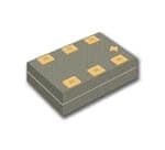
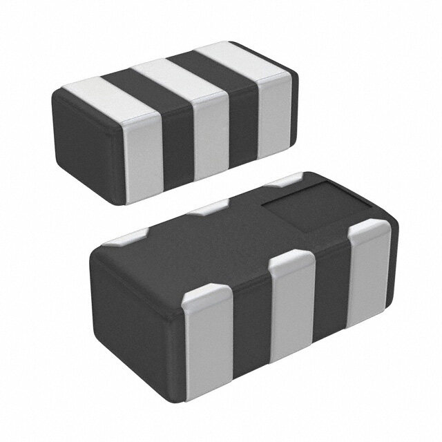
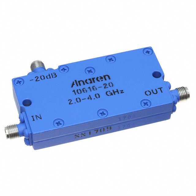
| 产品图片 |
|
| rohs | 符合RoHS无铅 / 符合限制有害物质指令(RoHS)规范要求 |
| 产品系列 | Anaren DC0710J5020AHFXinger® |
| mouser_ship_limit | 该产品可能需要其他文件才能进口到中国。 |
| 数据手册 | |
| 产品型号 | DC0710J5020AHF |
| RoHS指令信息 | |
| 产品 | Directional Couplers |
| 产品种类 | 信号调节 |
| 介入损耗 | 0.22 dB |
| 供应商器件封装 | 0805(2012 公制) |
| 其它名称 | 1173-1085-1 |
| 功率-最大值 | 2W |
| 包装 | 剪切带 (CT) |
| 商标 | Anaren |
| 商标名 | Xinger |
| 回波损耗 | 21.41dB |
| 封装 | Reel |
| 封装/外壳 | 0805(2012 公制) |
| 封装/箱体 | 0805 (2012 metric) |
| 工作温度范围 | - 55 C to + 85 C |
| 工厂包装数量 | 4000 |
| 应用 | 通用 |
| 插入损耗 | 0.22dB |
| 标准包装 | 1 |
| 端接类型 | SMD/SMT |
| 耦合器类型 | 标准 |
| 耦合系数 | 19.5dB |
| 隔离 | - |
| 频率 | 700MHz ~ 1GHz |
| 频率范围 | 700 MHz to 1000 MHz |

.jpg)


- 商务部:美国ITC正式对集成电路等产品启动337调查
- 曝三星4nm工艺存在良率问题 高通将骁龙8 Gen1或转产台积电
- 太阳诱电将投资9.5亿元在常州建新厂生产MLCC 预计2023年完工
- 英特尔发布欧洲新工厂建设计划 深化IDM 2.0 战略
- 台积电先进制程称霸业界 有大客户加持明年业绩稳了
- 达到5530亿美元!SIA预计今年全球半导体销售额将创下新高
- 英特尔拟将自动驾驶子公司Mobileye上市 估值或超500亿美元
- 三星加码芯片和SET,合并消费电子和移动部门,撤换高东真等 CEO
- 三星电子宣布重大人事变动 还合并消费电子和移动部门
- 海关总署:前11个月进口集成电路产品价值2.52万亿元 增长14.8%
PDF Datasheet 数据手册内容提取
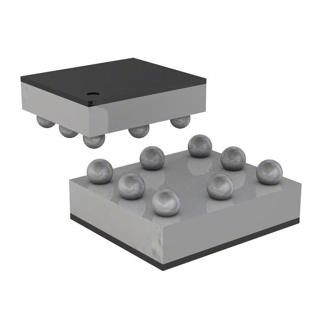
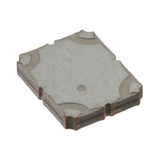
Model DC0710J5020AHF Rev E Ultra Low Profile 0805 20dB Directional Coupler Description The DC0710J5020AHF is a low cost, low profile sub-miniature high performance 20 dB directional coupler in an easy to use RoHS compliant, Halogen Free surface mount package. It is designed for 700 – 1000MHz applications including: WCDMA, CDMA, LTE700 and GSM850 / 900 applications. The DC0710J5020AHF is ideal for power detection, signal injection and other applications where low insertion loss signal monitoring is required. The DC0710J5020AHF is available on tape and reel for pick and place high volume manufacturing. All of the Xinger components are constructed from ceramic filled PTFE composites which possess excellent electrical and mechanical stability. All parts have been subjected to rigorous qualification testing and units are 100% RF tested. Detailed Electrical Specifications: Specifications subject to change without notice. ROOM (25˚C) Features: Frequency Power Frequency Mean Coupling Insertion Return Directivity • 700 – 1000 MHz (MHz) (dB) loss (dB) Loss (dB) (dB) Sensitivity Handling • Mean Coupling (dB) (Watts) 20dB Min Typ. Max Typ. Max Typ. Min Typ. Min Typ. Max Max • 0.58mm Height Profile • Ultra Low Insertion 700 - 1000 18.8 19.5 21 0.22 0.28 21.41 15.9 19.7 14.1 0.32 0.4 2 Loss • Surface Mountable • Tape & Reel 869-894 18.9 19.6 20.4 0.21 0.26 21.41 18.1 25.4 17.6 0.03 0.03 2 • RoHS Compliant • Halogen Free • -55°°°°C to 85°°°°C 925-960 19 19.7 20.7 0.22 0.28 21.46 16.8 21.9 15.6 0.08 0.09 2 **Specification based on performance of unit properly installed on microstrip printed circuit boards with 50 Ω nominal impedance. Outline Drawing TOP VIEW SIDE VIEW BOTTOM VIEW 4x 0.37 2.04±0.10 0.58±0.06 1 2 3 2x 0.15 1.29±0.10 6x 0.98 6x 0.22 6 5 4 Orientation Marker 6x Orientation Marker Denotes Pin Location 0.30 Denotes Pin Location 4x 0.65 PinConfiguration-1 Configuration-2 1 Direct Input 2 Isolated Coupled 3 Gnd Gnd Mechanical Outline 4 Gnd Gnd -Dimensions are in Millimeters 5 Coupled Isolated 6 Input Direct USA/Canada: (315) 432-8909 Visit us at Toll Free: (800) 411-6596 www.anaren.com Europe: +44 2392-232392 Asia: +86 512-62749282
Model DC0710J5020AHF Rev E Typical Performance: 700 MHz. to 1000 MHz (Configuration 1) Coupling (dB) 0 Directivity (dB) 0 -5 -5 -10 -10 -15 -20 -15 -25 -20 -30 -35 -25 -40 -45 -30 0.6 0.65 0.7 0.75 0.8 0.85 0.9 0.95 1 1.05 1.1 0.6 0.65 0.7 0.75 0.8 0.85 0.9 0.95 1 1.05 1.1 Freq [GHz] Freq [GHz] Return Loss at Input Port (dB) 0 Return Loss at Direct Port (dB) 0 -5 -5 -10 -10 -15 -15 -20 -20 -25 -25 -30 -30 -35 -35 -40 -40 -45 -45 0.6 0.65 0.7 0.75 0.8 0.85 0.9 0.95 1 1.05 1.1 0.6 0.65 0.7 0.75 0.8 0.85 0.9 0.95 1 1.05 1.1 Freq [GHz] Freq [GHz] Return Loss at Isolated Port (dB) 0 Return Loss at Coupled Port (dB) 0 -5 -5 -10 -10 -15 -15 -20 -20 -25 -25 -30 -30 -35 -35 -40 -40 -45 -45 0.6 0.65 0.7 0.75 0.8 0.85 0.9 0.95 1 1.05 1.1 0.6 0.65 0.7 0.75 0.8 0.85 0.9 0.95 1 1.05 1.1 Freq [GHz] Freq [GHz] USA/Canada: (315) 432-8909 Visit us at Toll Free: (800) 411-6596 www.anaren.com Europe: +44 2392-232392 Asia: +86 512-62749282
Model DC0710J5020AHF Rev E Insertion Loss (dB) 0 Transmission Loss (dB) 0 -0.5 -0.5 -1 -1 -1.5 -1.5 -2 -2 -2.5 -2.5 -3 -3 0.6 0.65 0.7 0.75 0.8 0.85 0.9 0.95 1 1.05 1.1 0.6 0.65 0.7 0.75 0.8 0.85 0.9 0.95 1 1.05 1.1 Freq [GHz] Freq [GHz] Wideband Performance: 0 to 8500MHz (Configuration 1) Coupling (dB) 0 Directivity (dB) 0 -5 -5 -10 -10 -15 -20 -15 -25 -20 -30 -35 -25 -40 -45 -30 1 2 3 4 5 6 7 8 1 2 3 4 5 6 7 8 Freq [GHz] Freq [GHz] Return Loss at Input Port (dB) 0 Return Loss at Direct Port (dB) 0 -5 -5 -10 -10 -15 -15 -20 -20 -25 -25 -30 -30 -35 -35 -40 -40 -45 -45 1 2 3 4 5 6 7 8 1 2 3 4 5 6 7 8 Freq [GHz] Freq [GHz] USA/Canada: (315) 432-8909 Visit us at Toll Free: (800) 411-6596 www.anaren.com Europe: +44 2392-232392 Asia: +86 512-62749282
Model DC0710J5020AHF Rev E Return Loss at Isolated Port (dB) 0 Return Loss at Coupled Port (dB) 0 -5 -5 -10 -10 -15 -15 -20 -20 -25 -25 -30 -30 -35 -35 -40 -40 -45 -45 1 2 3 4 5 6 7 8 1 2 3 4 5 6 7 8 Freq [GHz] Freq [GHz] Insertion Loss (dB) 0 Transmission Loss (dB) 0 -0.5 -0.5 -1 -1 -1.5 -1.5 -2 -2 -2.5 -2.5 -3 -3 1 2 3 4 5 6 7 8 1 2 3 4 5 6 7 8 Freq [GHz] Freq [GHz] USA/Canada: (315) 432-8909 Visit us at Toll Free: (800) 411-6596 www.anaren.com Europe: +44 2392-232392 Asia: +86 512-62749282
Model DC0710J5020AHF Rev E Definition of Measured Specifications Mathematical Mathematical Parameter Definition Representation Representation for Pin Configuration 1 for Pin Configuration 2 The impedance match of the coupler to a 50Ω Return Loss (dB)= Return Loss (dB)= Return Loss system. Return Loss is an 20log (S ) i =1,2,3,4 20log (S ) i =1,2,3,4 alternate means to 10 ii 10 ii express VSWR. At a given frequency (ω ), Coupling (dB) = Coupling (dB) = coupling is the input powner C =20log S C =20log S 10 34 10 21 divided by the power at the coupled port. Mean Mean Coupling (dB) = Mean Coupling (dB) = Mean Coupling coupling is the average N N value of the coupling ∑C(ω) ∑C(ω) n n values in the band. N is n=1 n=1 the number of frequencies N N in the band. The input power divided Insertion Loss by the sum of the power at 10log (S 2 + S 2) 10log (S 2 + S 2) 10 14 34 10 41 21 the two output ports. The input power divided Transmission by the power at the direct 20log (S ) 20log (S ) Loss 10 14 10 41 port. The power at the coupled S S Directivity port divided by the power 20log ( 24 ) 20log ( 31 ) 10 S 10 S at the isolated port. 34 21 The decibel difference between the maximum in Frequency (Max Coupling (dB) – Min (Max Coupling (dB) – Min band coupling value and Sensitivity Coupling (dB))/2 Coupling (dB))/2 the minimum in band coupling value. *100% RF test is performed on configuration 1 where port 1 is connected to pin1, port 2 is connected to pin 2, port 3 is connected to pin 5 and port 4 is connected to pin 6. USA/Canada: (315) 432-8909 Visit us at Toll Free: (800) 411-6596 www.anaren.com Europe: +44 2392-232392 Asia: +86 512-62749282
Model DC0710J5020AHF Rev E Mounting Configuration: In order for Xinger surface mount components to work optimally, the proper impedance transmission lines must be used to connect to the RF ports. If this condition is not satisfied, insertion loss, Isolation and VSWR may not meet published specifications. All of the Xinger components are constructed from organic PTFE based composites which possess excellent electrical and mechanical stability. Xinger components are compliant to a variety of ROHS and Green standards and ready for Pb-free soldering processes. Pads are Gold plated with a Nickel barrier. An example of the PCB footprint used in the testing of these parts is shown below. In specific designs, the transmission line widths need to be adjusted to the unique dielectric coefficients and thicknesses as well as varying pick and place equipment tolerances. .41 .25 Plated thru holes to ground .33 .66 .04 Plated thru 4x Transmission holes to lines ground Circuit Pattern Footprint Pad (s) Solder Resist Dimensions are in Millimeters Mounting Footprint USA/Canada: (315) 432-8909 Visit us at Toll Free: (800) 411-6596 www.anaren.com Europe: +44 2392-232392 Asia: +86 512-62749282
Model DC0710J5020AHF Rev E Packaging and Ordering Information Parts are available in reel and are packaged per EIA 481-D. Parts are oriented in tape and reel as shown below. Minimum order quantities are 4000 per reel. 2.00 4.00 1.00 1.75 3.50 8.00 2.41 1.60 4.00 .25 USA/Canada: (315) 432-8909 Visit us at Toll Free: (800) 411-6596 www.anaren.com Europe: +44 2392-232392 Asia: +86 512-62749282
Mouser Electronics Authorized Distributor Click to View Pricing, Inventory, Delivery & Lifecycle Information: A naren: DC0710J5020AHF