 Datasheet下载
- 型号: CS70-B2GA151KYNS
- 制造商: TDK
- 库位|库存: xxxx|xxxx
- 要求:
| 数量阶梯 | 香港交货 | 国内含税 |
| +xxxx | $xxxx | ¥xxxx |
查看当月历史价格
查看今年历史价格
CS70-B2GA151KYNS产品简介:
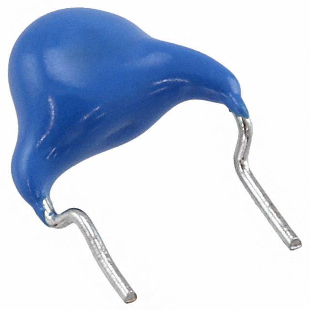
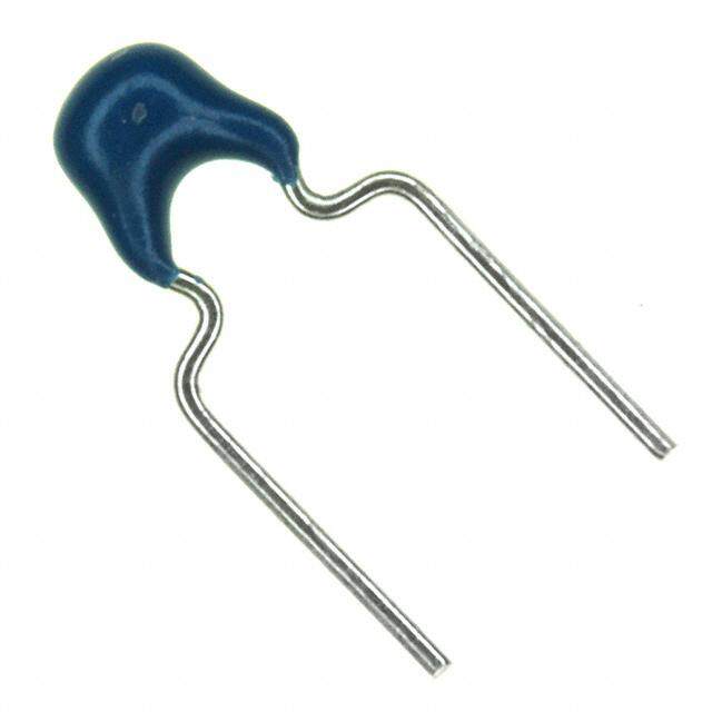
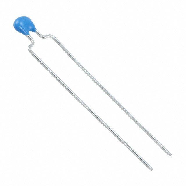
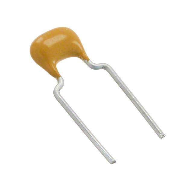
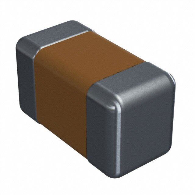
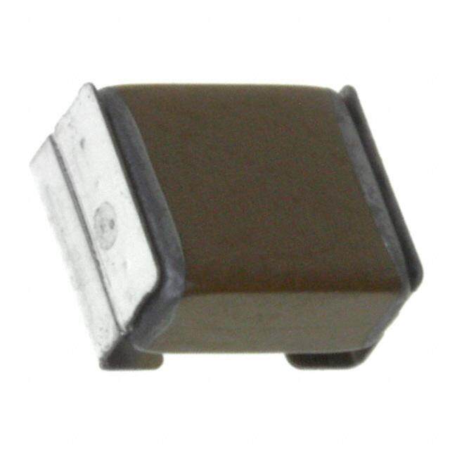
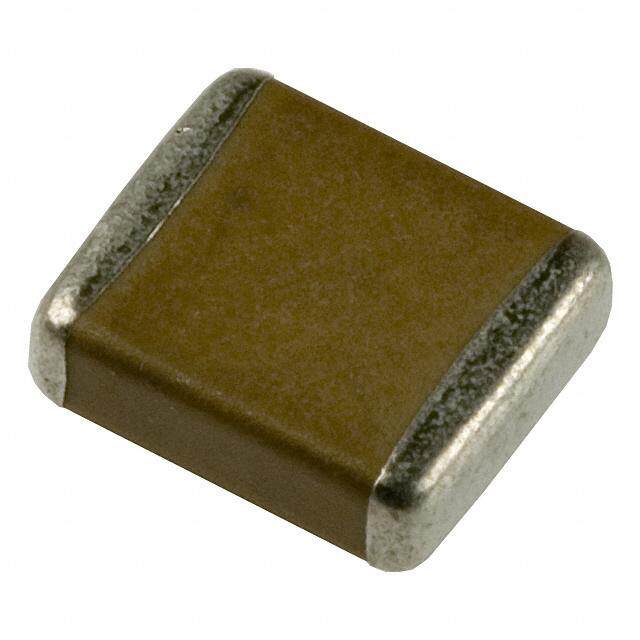
ICGOO电子元器件商城为您提供CS70-B2GA151KYNS由TDK设计生产,在icgoo商城现货销售,并且可以通过原厂、代理商等渠道进行代购。 CS70-B2GA151KYNS价格参考。TDKCS70-B2GA151KYNS封装/规格:陶瓷电容器, 150pF ±10% 250V 陶瓷电容器 B 径向,圆片式。您可以下载CS70-B2GA151KYNS参考资料、Datasheet数据手册功能说明书,资料中有CS70-B2GA151KYNS 详细功能的应用电路图电压和使用方法及教程。
TDK Corporation生产的陶瓷电容器型号CS70-B2GA151KYNS,属于多层陶瓷电容器(MLCC)系列。其主要应用场景包括:

1. 电源滤波:该型号电容器适用于电源电路中的滤波功能,能够有效抑制高频噪声,确保电源输出的稳定性。常见于开关电源、DC-DC转换器等设备中。

2. 信号耦合与解耦:在电子电路中,CS70-B2GA151KYNS可用于信号耦合和解耦,帮助隔离直流成分并传递交流信号,广泛应用于射频(RF)模块、通信设备及音频处理电路。

3. 振荡电路:作为振荡电路中的关键元件,该电容器可与其他元器件配合,生成稳定的时钟信号,适用于微控制器单元(MCU)、时钟发生器等场景。

4. ESD保护与噪声抑制:凭借其优异的高频特性,该型号能够有效抑制电磁干扰(EMI),同时提供静电放电(ESD)保护功能,适合用于消费电子、工业控制和汽车电子领域。

5. 高频应用:由于其低ESR(等效串联电阻)和低ESL(等效串联电感)特性,CS70-B2GA151KYNS特别适合高频环境下的应用,如无线通信设备、雷达系统和高速数据传输接口。

6. 汽车电子:该型号符合车规级要求,能够在极端温度和振动条件下稳定工作,适用于车载信息娱乐系统、高级驾驶辅助系统(ADAS)和电动车辆(EV)的逆变器模块。

总之,CS70-B2GA151KYNS以其高可靠性、小尺寸和优良的电气性能,成为各类电子设备中不可或缺的关键元件,尤其适合对稳定性、噪声抑制和高频响应有较高要求的应用场景。
| 参数 | 数值 |
| 产品目录 | |
| 描述 | CAP CER 150PF 250VAC 10% RADIAL瓷片电容器 X1Y2 150pF 10% 250VAC |
| 产品分类 | |
| 品牌 | TDK |
| 产品手册 | |
| 产品图片 |
|
| rohs | 符合RoHS无铅 / 符合限制有害物质指令(RoHS)规范要求 |
| 产品系列 | 陶瓷电容器,瓷片电容器,TDK CS70-B2GA151KYNSCS |
| 数据手册 | |
| 产品型号 | CS70-B2GA151KYNS |
| 产品 | Ceramic Disc Capacitors |
| 产品目录绘图 |
|
| 产品目录页面 | |
| 产品种类 | 瓷片电容器 |
| 其它名称 | 445-2416 |
| 包装 | 散装 |
| 厚度 | 7 mm |
| 厚度(最大值) | - |
| 商标 | TDK |
| 外壳宽度 | 7 mm |
| 外壳直径 | 7 mm |
| 大小/尺寸 | 0.276" 直径(7.00mm) |
| 安装类型 | 通孔 |
| 容差 | 10 % |
| 封装 | Bulk |
| 封装/外壳 | 径向,圆盘 |
| 工作温度 | -25°C ~ 105°C |
| 工作温度范围 | - 40 C to + 125 C |
| 工厂包装数量 | 1000 |
| 应用 | Safety |
| 引线形式 | 直形 |
| 引线直径 | 0.6 mm |
| 引线类型 | Vertical Kink |
| 引线间距 | 0.295"(7.50mm) |
| 引线间隔 | 7.5 mm |
| 最大工作温度 | + 125 C |
| 最小工作温度 | - 40 C |
| 标准包装 | 1,000 |
| 温度系数 | B |
| 温度系数/代码 | 10 % |
| 特性 | 高电压 |
| 电压-额定 | 250VAC |
| 电压额定值 | 400 VAC |
| 电压额定值AC | 400 V |
| 电容 | 150 pF |
| 端接类型 | Radial |
| 等级 | X1Y2 |
| 类 | 2 |
| 类型 | High Voltage Ceramic Disc Capacitors |
| 系列 | CS |
| 高度-安装(最大值) | 0.433"(11.00mm) |


- 商务部:美国ITC正式对集成电路等产品启动337调查
- 曝三星4nm工艺存在良率问题 高通将骁龙8 Gen1或转产台积电
- 太阳诱电将投资9.5亿元在常州建新厂生产MLCC 预计2023年完工
- 英特尔发布欧洲新工厂建设计划 深化IDM 2.0 战略
- 台积电先进制程称霸业界 有大客户加持明年业绩稳了
- 达到5530亿美元!SIA预计今年全球半导体销售额将创下新高
- 英特尔拟将自动驾驶子公司Mobileye上市 估值或超500亿美元
- 三星加码芯片和SET,合并消费电子和移动部门,撤换高东真等 CEO
- 三星电子宣布重大人事变动 还合并消费电子和移动部门
- 海关总署:前11个月进口集成电路产品价值2.52万亿元 增长14.8%


PDF Datasheet 数据手册内容提取
Mid-high Voltage Ceramic Capacitors Disk type with lead Safety standard approved CS series Issue date: October 2011 • All specifications are subject to change without notice. (cid:127) Conformity to RoHS Directive: This means that, in conformity with EU Directive 2002/95/EC, lead, cadmium, mercury, hexavalent chromium, and specific bromine-based flame retardants, PBB and PBDE, have not been used, except for exempted applications.
(1/3) Mid-high Voltage Ceramic Capacitors(Disk with Lead) Conformity to RoHS Directive Safety Standard Approved CS Series BASIC INSULATION TYPE/Operating temperature range: –25 to +105°C(UL standard: –25 to +85°C) CLASS 2 HIGH DIELECTRIC FEATURES PRODUCT IDENTIFICATION (cid:127) Flame-resistant reinforced outer insulation prevents fires, electri- CS 11 -E 2GA 222 M Y N S A cal shock, and other potential hazards. (1) (2) (3) (4) (5) (6) (7) (8) (9) (10) (cid:127) Compliant with the safety standards of 11 countries. (cid:127) It has a withstand voltage of AC.2600V (1)Type (cid:127) This product is compatible with halogen-free external resin (2)Shape coating (we recommend halogen-free products as standard). (3)Capacitance temperature characteristics (4)Rated voltage CAPACITANCE TEMPERATURE CHARACTERISTICS (5)Nominal capacitance AND TOLERANCE (6)Capacitance tolerance Test temperature Capacitance (7)Class Temperature characteristics range tolerance (8)Lead type B(±10%) –25 to +85°C K(±10%) (9) Safety standard E(+20, –55%) –25 to +85°C M(±20%) (10) Halogen-free compatible product F(+30, –80%) –25 to +85°C M(±20%) CAPACITANCE AND DIMENSIONS Part No. Capacitance Dimensions(mm) Capacitance Capacitance Taping temperature Halogen-free product Current product (pF) tolerance D max.T max.F d dimensions characteristics CS70-B2GA101KY(cid:134)∗SA CS70-B2GA101KY(cid:134)∗S 100 K(±10%) 7.0 7.0 7.5±1.5 0.6±0.05 V2 CS70-B2GA151KY(cid:134)SA CS70-B2GA151KY(cid:134)S 150 K(±10%) 7.0 7.0 7.5±1.5 0.6±0.05 V2 CS70-B2GA221KY(cid:134)SA CS70-B2GA221KY(cid:134)S 220 K(±10%) 7.0 7.0 7.5±1.5 0.6±0.05 V2 CS85-B2GA331KY(cid:134)SA CS85-B2GA331KY(cid:134)S B(±10%) 330 K(±10%) 8.5 7.0 7.5±1.5 0.6±0.05 V2 CS85-B2GA471KY(cid:134)SA CS85-B2GA471KY(cid:134)S 470 K(±10%) 8.5 7.0 7.5±1.5 0.6±0.05 V2 CS95-B2GA681KY(cid:134)SA CS95-B2GA681KY(cid:134)S 680 K(±10%) 9.5 7.0 7.5±1.5 0.6±0.05 V2 CS10-B2GA102KY(cid:134)SA CS10-B2GA102KY(cid:134)S 1,000 K(±10%) 10.0 7.0 7.5±1.5 0.6±0.05 V2 CS80-E2GA102MY(cid:134)SA CS80-E2GA102MY(cid:134)S 1,000 M(±20%) 8.0 7.0 7.5±1.5 0.6±0.05 V2 CS90-E2GA152MY(cid:134)SA CS90-E2GA152MY(cid:134)S 1,500 M(±20%) 9.0 7.0 7.5±1.5 0.6±0.05 V2 CS11-E2GA222MY(cid:134)SA CS11-E2GA222MY(cid:134)S 2,200 M(±20%) 10.5 7.0 7.5±1.5 0.6±0.05 V2 E(+20, –55%) CS13-E2GA332MY(cid:134)SA CS13-E2GA332MY(cid:134)S 3,300 M(±20%) 12.5 7.0 7.5±1.5 0.6±0.05 V2 CS14-E2GA392MY(cid:134)SA CS14-E2GA392MY(cid:134)S 3,900 M(±20%) 13.5 7.0 7.5±1.5 0.6±0.05 V2 CS15-E2GA472MY(cid:134)SA CS15-E2GA472MY(cid:134)S 4,700 M(±20%) 14.5 7.0 7.5±1.5 0.6±0.05 V3 CS12-F2GA472MY(cid:134)SA CS12-F2GA472MY(cid:134)S 4,700 M(±20%) 12.0 7.0 7.5±1.5 0.6±0.05 V2 F(+30, –80%) CS17-F2GA103MY(cid:134)SA CS17-F2GA103MY(cid:134)S 10,000 M(±20%) 16.5 7.0 10±2 0.6±0.05 — ∗ (cid:134) : Lead shape symbol LIST OF STANDARD LEAD SHAPES The lead type is indicated by the letter which is the 15th character of the product name. Example) TDK Product Name: CS11-E2GA222MYNSA N: Lead type (Vertical kink, Short) Dimensions in mm Long lead Short lead Taping Symbol G Symbol N Symbol V D T D T D T x. a x. x. m ma ma 4 4 4 Vertical kink +1.56–0.5 min. F d ±1 1 5 5 2 F d (cid:127) We recommend using a vertical kink type. (cid:127) For bulk products, we recommend a short lead type with the symbol N. (cid:127) Conformity to RoHS Directive: This means that, in conformity with EU Directive 2002/95/EC, lead, cadmium, mercury, hexavalent chromium, and specific bromine-based flame retardants, PBB and PBDE, have not been used, except for exempted applications. (cid:127) All specifications are subject to change without notice. 005-03 / 20111003 / e4b3_cs.fm
(2/3) HALOGEN-FREE PRODUCT MARKINGS Item Marking examples 1. Series CS 2. Nominal capacitance 222(2200pF) CS222M 3. Capacitance tolerance M(±20%) 250 X1Y2 4. Rated voltage Eac 250V (AC.250V) 15 5. Sub-class of safety performance X1Y2 6. TDK’s logogram 7. Date code 15 (2011.5)∗ (Marking position is reference.) ∗ Year and month of production: last digit of year + month denoted by 1, 2, 3, 4, 5, 6, 7, 8, 9, O (October), N (November), or D (December). ∗ The expression has become simplified due to a revision in the standards. INTERNATIONALLY CERTIFIED STATUS / IEC60384-14 EN60384-14 Approved Safety Standard No. Temperature Insulation Rated voltage Approval report No. Standard No. standard of IEC characteristics sub-class Eac(V) Japan Taiwan Xiamen IEC 60065 BS EN 60065 BSI B, E, F X1, Y2 250 KM37103 KM37103 KM37103 IEC 60384-14 BS EN60384-14 VDE IEC 60384-14 EN 60384-14 B, E, F X1, Y2 250 40029781 40029781 40029781 SEV IEC 60384-14 EN 60384-14 B, E, F X1, Y2 250 10.0120 10.0120 10.0120 SEMKO IEC 60384-14 EN 60384-14 B, E, F X1, Y2 250 912461 912461 912461 NEMKO IEC 60384-14 EN 60384-14 B, E, F X1, Y2 250 P09211677 P09211677 P09211677 DEMKO IEC 60384-14 EN 60384-14 B, E, F X1, Y2 250 315269-01 315269-01 315269-01 FIMKO IEC 60384-14 EN 60384-14 B, E, F X1, Y2 250 FI 25553 FI 25553 FI 25553 IMQ IEC 60384-14 EN 60384-14 B, E, F X1, Y2 250 V3692 V3692 V3692 SAA IEC 60065 AS3250 B, E, F — 400 CS6268 CS6268 CS6268 UL — UL 1414 B, E, F (X, Y) 250 E37861 E37861 E37861 2278972 2278972 2278972 CSA IEC 60384-14 CAN/CSA-E60384-14 B, E, F (X, Y) 250 (LR 35801) (LR 35801) (LR 35801) CQC IEC 60384-14 GB-T 14472-1998 B, E, F X1, Y2 250 CQC10001051610 CQC10001051637 CQC03001004815 (cid:127) Certificate numbers shall be changed owing to the revisions of the related standards. CURRENT PRODUCT MARKINGS Item Marking examples 1. Series CS Front Back 2. Nominal capacitance 222(2200pF) 3. Capacitance tolerance M(±20%) CS222M 4. Rated voltage Eac 250V (AC.250V) BSI 5. Withstand voltage Eac X1Y2 2X510YV2 T15J508 6. Sub-class of safety performance 7. TDK’s logogram 15 (2011.5)∗ 8. Date code 9. Regulatory body safety standards compliance markings (Marking position of the monogram is reference.) BSI SEV FIMKO NEMKO (U.K.) BSI (Switzerland) TJ508 (Finland) (Norway) SEMKO UL DEMKO IMQ (Sweden) (U.S.A.) (Denmark) (Italy) VDE CSA (Germany) (Canada) ∗ Year and month of production: last digit of year + month denoted by 1, 2, 3, 4, 5, 6, 7, 8, 9, O (October), N (November), or D (December). INTERNATIONALLY CERTIFIED STATUS / IEC60384-14 EN60384-14 Approved Safety Standard No. Temperature Insulation Rated voltage Approval report No. Standard No. standard of IEC characteristics sub-class Eac(V) Japan Taiwan Xiamen IEC 60065 BS EN 60065 BSI B, E, F X1, Y2 250 226494 226494 226494 IEC 60384-14 BS EN60384-14 VDE IEC 60384-14 EN60384-14 B, E, F X1, Y2 250 138559 138560 122006 SEV IEC 60384-14 EN60384-14 B, E, F X1, Y2 250 09.0962 09.0962 09.0962 SEMKO IEC 60384-14 EN60384-14 B, E, F X1, Y2 250 915556 915556 915394 NEMKO IEC 60384-14 EN60384-14 B, E, F X1, Y2 250 P09211507 P09211507 P08209309 DEMKO IEC 60384-14 EN60384-14 B, E, F X1, Y2 250 315179-01 315179-01 314664-02 FIMKO IEC 60384-14 EN60384-14 B, E, F X1, Y2 250 FI 25453 FI 25453 FI 24306A1 IMQ IEC 60384-14 EN60384-14 B, E, F X1, Y2 250 V3692 V3692 V3692 SAA IEC 60065 AS3250 B, E, F — 400 6268 6268 6268 UL — UL 1414 B, E, F (X, Y) 250 E37861 E37861 E37861 CSA — CSA C22.2 No.0 & No.1 B, E, F (X, Y) 250 LR35801 LR65972 LR65972 (cid:127) Certificate numbers shall be changed owing to the revisions of the related standards. (cid:127) All specifications are subject to change without notice. 005-03 / 20111003 / e4b3_cs.fm
(3/3) TAPING DIMEMSIONS VERTICAL KINK LEAD TYPE P D T P T P2 ∆h ∆h D P2 ∆h ∆h A A H1 H0 W2 S C H1 H0 W2 S C W1 L H0 W1 L H0 W0 W W0 W P1 F D0 P0 P1 F D0 P0 ød ød t V1, V2 V3 t Dimensions(mm) Item Symbol Remarks V1 V2 V3 Body diameter D Depends on the specification of each product. Body thickness T Depends on the specification of each product. Lead-wire diameter ød 0.6±0.05 0.6±0.05 0.6±0.05 Pitch of component P 12.7±1.0 15.0±1.0 30.0±1.0 Including the slant of body Feed hole pitch P0 12.7±0.3 15.0±0.3 15.0±0.3 Excepting the tape splicing part Feed hole center to lead P1 3.85±0.7 3.75±0.7 3.75±0.7 Feed hole center to component P2 6.35±1.3 7.5±1.3 7.5±1.3 center Lead-to lead distance F 5+0.8, –0.2 7.5±0.8 7.5±0.8 Measuring point is bottom kink Component alignment ∆h 0±2.0 0±2.0 0±2.0 Including the slanting body due to bending lead-wire Tape width W 18.0+1.0, –0.5 18.0+1.0, –0.5 18.0+1.0, –0.5 Adhesive tape width W0 11.5min. 11.5min. 11.5min. Hole position W1 9.0±0.5 9.0±0.5 9.0±0.5 Adhesive tape position W2 3.0max. 3.0max. 3.0max. Adhesive tape do not stick out the tape Bottom of kink from tape center H0 16.0+1.5, –0.5 16.0+1.5, –0.5 16.0+1.5, –0.5 Height of body from tape center H1 46.0max. 46.0max. 46.0max. Lead-wire protrusion 1.0max. 1.0max. 1.0max. Feed hole diameter D0 4.0±0.2 4.0±0.2 4.0±0.2 Total tape thickness t 0.6±0.3 0.6±0.3 0.6±0.3 Do not including adhesive tape Length of snipped lead L 11.0max. 11.0max. 11.0max. Coating on lead C 4.0max. 4.0max. 4.0max. Height of kink A 4.0max. 4.0max. 4.0max. Measuring point is bottom kink Spring action S 2.0max. 2.0max. 2.0max. (cid:127) For more information about products with other capacitance or other data, please contact us. (cid:127) All specifications are subject to change without notice. 005-03 / 20111003 / e4b3_cs.fm