ICGOO在线商城 > 开发板,套件,编程器 > 评估和演示板和套件 > CP2108EK
 Datasheet下载
- 型号: CP2108EK
- 制造商: Silicon Laboratories
- 库位|库存: xxxx|xxxx
- 要求:
| 数量阶梯 | 香港交货 | 国内含税 |
| +xxxx | $xxxx | ¥xxxx |
查看当月历史价格
查看今年历史价格
CP2108EK产品简介:
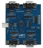
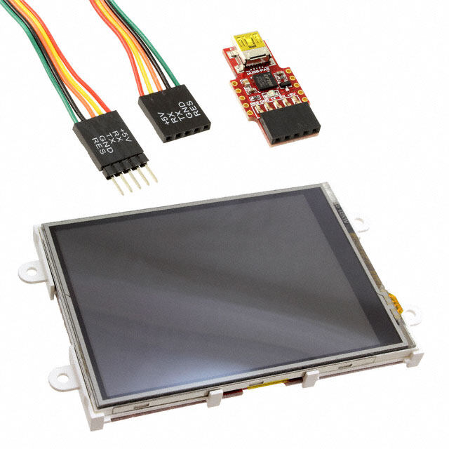
ICGOO电子元器件商城为您提供CP2108EK由Silicon Laboratories设计生产,在icgoo商城现货销售,并且可以通过原厂、代理商等渠道进行代购。 CP2108EK价格参考¥686.15-¥686.15。Silicon LaboratoriesCP2108EK封装/规格:评估和演示板和套件, CP2108 USB 2.0 to UART (RS232/RS422/RS485) Bridge Interface Evaluation Board。您可以下载CP2108EK参考资料、Datasheet数据手册功能说明书,资料中有CP2108EK 详细功能的应用电路图电压和使用方法及教程。
Silicon Labs的CP2108EK是一款基于CP2108 USB-to-UART桥接器的评估和演示套件。该开发套件主要用于帮助工程师快速评估和开发基于CP2108芯片的USB转串口通信应用。CP2108EK的应用场景主要包括:

1. 嵌入式系统开发:用于连接微控制器或嵌入式设备与PC之间的USB转UART通信,便于调试与数据传输。

2. 工业自动化:在工业控制和监测系统中,实现设备与上位机之间的稳定串口通信。

3. 物联网(IoT)设备开发:为传感器、网关等IoT设备提供可靠的USB转串口接口,支持固件更新和数据传输。

4. 通信模块测试:用于测试和验证Wi-Fi、蓝牙、Zigbee等无线通信模块的串口连接性能。

5. 消费类电子产品开发:支持打印机、扫描仪、POS机等设备进行USB与串口之间的协议转换。

6. 现场固件升级:支持通过USB接口对设备进行便捷的固件更新和维护。

CP2108EK提供了完整的硬件平台和配套软件支持,有助于加快产品开发周期并简化集成过程。
| 参数 | 数值 |
| 产品目录 | 编程器,开发系统嵌入式解决方案 |
| 描述 | CP2108 EVALUATION KIT界面开发工具 CP2108 Eval kit |
| 产品分类 | |
| 品牌 | Silicon Laboratories IncSilicon Labs |
| 产品手册 | |
| 产品图片 |
|
| rohs | 符合RoHS无铅 / 符合限制有害物质指令(RoHS)规范要求 |
| 产品系列 | 模拟与数字IC开发工具,界面开发工具,Silicon Labs CP2108EK- |
| 数据手册 | |
| 产品型号 | CP2108EKCP2108EK |
| 主要属性 | 全速(12Mbps) |
| 主要用途 | 接口,USB 2.0 至 UART(RS232/RS422/RS485)电桥 |
| 产品 | Evaluation Kits |
| 产品培训模块 | http://www.digikey.cn/PTM/IndividualPTM.page?site=cn&lang=zhs&ptm=30399 |
| 产品种类 | 界面开发工具 |
| 使用的IC/零件 | CP2108 |
| 其它名称 | 336-2404 |
| 商标 | Silicon Labs |
| 封装 | Bulk |
| 嵌入式 | - |
| 工作电源电压 | 1.8 V to 3.6 V |
| 工具用于评估 | CP2108 |
| 所含物品 | 板,线缆 |
| 接口类型 | RS232, RS485, UART, USB |
| 标准包装 | 1 |
| 用于 | CP2108 |
| 类型 | USB to UART |
| 系列 | CP2108 |
| 辅助属性 | LED 状态指示器 |


- 商务部:美国ITC正式对集成电路等产品启动337调查
- 曝三星4nm工艺存在良率问题 高通将骁龙8 Gen1或转产台积电
- 太阳诱电将投资9.5亿元在常州建新厂生产MLCC 预计2023年完工
- 英特尔发布欧洲新工厂建设计划 深化IDM 2.0 战略
- 台积电先进制程称霸业界 有大客户加持明年业绩稳了
- 达到5530亿美元!SIA预计今年全球半导体销售额将创下新高
- 英特尔拟将自动驾驶子公司Mobileye上市 估值或超500亿美元
- 三星加码芯片和SET,合并消费电子和移动部门,撤换高东真等 CEO
- 三星电子宣布重大人事变动 还合并消费电子和移动部门
- 海关总署:前11个月进口集成电路产品价值2.52万亿元 增长14.8%


PDF Datasheet 数据手册内容提取
AN721: USBXpress™ Device Configuration and Programming Guide Silicon Labs offers several USBXpress single-chip connectivity bridge solutions to support USB-to-serial protocols, as well as KEY POINTS specialized bridges for the human interface device (HID) class • Use Xpress Configurator in Simplicity and USB audio applications. Studio to configure the USBXpress device. • Obtain a unique Product ID from Silicon Each of these devices has many user-customizable options which can determine the Labs or USB.org. device's behavior, from how the device will appear to the host machine, to specialized • Order pre-programmed parts from Silicon device options such as interface and pin configurations Labs, or perform production programming with the provided Standalone This document discusses how to configure the options available on these devices us- Manufacturing Tools. ing the tools provided with Simplicity Studio. Simplicity Studio can be downloaded from the Silicon Labs website: http://www.silabs.com/simplicity. This document also covers the steps necessary required to perform production programming as well as how to or- der pre-programmed parts from Silicon Labs with a desired configuration. silabs.com | Smart. Connected. Energy-friendly. Rev. 1.4
AN721: USBXpress™ Device Configuration and Programming Guide Introduction 1. Introduction This document explains the steps required to customize a USBXpress device. It is intended for developers creating products based on the CP210x/CP211x/CP2130 USB Bridge Controllers. It contains information about obtaining a Vendor ID (VID) and Product ID (PID) for a CP210x/CP211x/CP2130 product and describes the steps necessary for customizing the device descriptors. Refer to http:// www.silabs.com/interface for the latest revisions of this document and other application notes related to the CP210x/CP211x/CP2130 device families. 1.1 USB Vendor IDs and Product IDs Each device on a USB bus must have a unique Vendor ID (VID), Product ID (PID), and serial number combination. This ID system uniquely identifies the different devices on the bus to avoid conflicts. The PC matches the VID/PID of the device to that of installed drivers (if needed) to be used for the USB device. The VID/PID must be unique in that each USB device with the same VID/PID will use the same driver, and it is strongly recommended to make the PID unique to a particular design. Vendor IDs are owned by the vendor company and assigned by the USB Implementers Forum (USB-IF) only. The owner of a particular Vendor ID then owns all possible Product IDs under this Vendor ID. Details about obtaining a unique VID can be found at http:// www.usb.org/developers/vendor. It is also possible to utilize the Silicon Labs VID with a unique PID. The default Silicon Labs VID is 0x10C4 and the default Silicon Labs PID is dependent on the device. To request a unique PID for your CP210x/CP211x/CP2130-based product, visit http://www.silabs.com/ RequestPID. Note: Customization of the USB strings is optional, but is strongly recommended. A unique VID/PID combination will prevent the driver from conflicting with any other USB driver. 1.2 USB Logos and Certification Testing USB is a widely used peripheral. The USB Implementers Forum, Inc. (USB-IF) has introduced trademark-protected logos for use with qualified USB products. To use the logo, USB products are required to meet the standards of the USB Implementers Forum. For a product to have compliance and/or certification implies that the USB product has been tested by the USB-IF to meet the specification. Each type of USB product requires specific testing to be listed on the Integrators List. This is important not only to OEMs but to con- sumers because products tested and certified by the USB-IF are assured to work together. Compliance testing exists to help manufac- turers measure how well their products match the respective USB specification. If a product has passed USB-IF compliance testing, the company can use the USB logo on the products. To obtain the right to license the USB-IF logo, register the product's VID and PID with USB-IF and submit the product to the USB-IF Compliance Program. USB-IF Compliance Program details are available at http://www.usb.org/developers/compliance. Once the product is certified, it can be added to the USB-IF Integrators List, and the “Certified USB” logo can be used on the product. silabs.com | Smart. Connected. Energy-friendly. Rev. 1.4 | 1
AN721: USBXpress™ Device Configuration and Programming Guide Basic Device Customization 2. Basic Device Customization Each family of devices has slightly different requirements for configuration. The CP210x devices require a Virtual Com Port driver, pro- vided by Silicon Labs, to be installed on the host machine before they can be detected and programmed. The CP2130 devices similarly require a separate USB-to-SPI driver. The CP211x devices do not require drivers since they are HID class devices, which are natively supported by most operating systems. The next three sections describe the recommended steps for customizing the device based on the family. 2.1 Customizing the CP210x Non-HID USB Devices The steps to customize the CP210x USBXpress devices are as follows: 1.Request a unique PID from Silicon Labs for your new product design:http://www.silabs.com/RequestPID, or obtain a VID/PID from usb.org. 2.Download the VCP driver appropriate for your operating system here: http://www.silabs.com/products/mcu/pages/usbtouartbridg- evcpdrivers.aspx The stock VCP driver from the website should match the default VID and PID on the CP210x device. The VCP driver must be installed with matching VID and PID to communicate to the device. 3.Use 3.1 Xpress Configurator to change the descriptors in the programmable memory of the device. 4.(USBXpress Driver Users Only): If the desired driver is USBXpress, it can be download here: http://www.silabs.com/usbxpress. This driver allows direct access using Silicon Labs API commands to control the device, rather than having to operate on the de- vice as if it were a COM port. This driver, by default, does not match the default VID/PID of the CP210x devices. In order to use this driver, the devices or driver (or both) must be customized to have a matching VID/PID combination. See the tables at the end of this section for the default driver and device VID/PIDs. 5.Use the USB Driver Customization Wizard and instructions in AN220SW and AN220: USB Driver Customization http:// www.silabs.com/products/Interface/Pages/interface-application-notes.aspx to update the driver for the new PID and any other de- scriptors that have been changed from Step 3. 6.(Microsoft Windows Only): The customized driver is eligible for WHQL re-seller submissions to certify the driver. These submis- sions do not have the high cost and testing requirements of an original driver submission. To certify a customized WinUSB driver, register at the WinQual site: (https://sysdev.microsoft.com) to obtain a WinQual account with your company. Internet Explorer is the only web browser that can be used with the WHQL web site. A Verisign ID is needed to register an account (instructions for obtain- ing one are available at the Microsoft web site: http://msdn.microsoft.com/en-us/library/windows/hardware/hh801887?ppud=4. The correct Verisign ID is the CodeSigner Standard: http://www.verisign.com/code-signing/microsoft-authenticode/index.html?sl=head- er. 7.(Microsoft Windows Only): After obtaining a WinQual account, notify the Silicon Labs support team (http://www.silabs.com/contact- support) (click on “Open a support request”) to be added as a registered Reseller. Provide the driver type (CP2130 WinUSB) and version (e.g., 1.0) when requesting Reseller status. 8.(Microsoft Windows Only): Silicon Labs will add your company as a registered reseller. Your company must complete the provided directions to finish the recertification process. Note: For further detailed instructions on Microsoft’s submission process for recertification for a customized driver, please view applica- tion note AN807: Recertifying a Customized Windows HCK Driver Package, here: http://www.silabs.com/products/Interface/Pages/inter- face-application-notes.aspx. The CP210x family of devices provides communication from USB to UART. These devices require drivers on the host machine in order to interface with the device. Silicon Labs provides two sets of drivers to interface with the device: 1.Virtual COM Port (VCP) Drivers (http://www.silabs.com/vcpdrivers) — This driver allows the device to appear to the PC’s applica- tion software as a COM port. 2.USBXpress Drivers (http://www.silabs.com/usbxpress) — This driver provides a proprietary API in order for applications to commu- nicate to the device without appearing as a COM port. Only one driver can be associated with a particular device at a time. Drivers are associated with devices based on matching VID and PID combinations. The VCP drivers must generally be installed on a machine if interfacing with or configuring a CP210x device that is programmed with factory default settings. This is required since the VCP drivers, by default, match the default VID and PID combination of CP210x devices. In order to use a particular driver with a device, either the driver or the device must be customized so that the VID/PID combination matches on both the device and the driver. For example, if a device is to be used with the default USBXpress driver, its VID and PID must be changed to 0x10C4 and 0xEA61, respectively, since these are the defaults for the USBXpress driver. silabs.com | Smart. Connected. Energy-friendly. Rev. 1.4 | 2
AN721: USBXpress™ Device Configuration and Programming Guide Basic Device Customization The tables below show the default VID and PID values for the device and drivers. To establish communication with the driver, the VID and PID of the device must match the driver. Notice that the default CP210x device VID and PID match the default VCP driver VID and PID numbers. Table 2.1. Default Device VID/PID Settings Device Default VID Default PID CP2101-CP2104 0x10C4 0xEA60 CP2105 0x10C4 0xEA70 CP2108 0x10C4 0xEA71 Table 2.2. Default VCP Driver VID/PID Settings Device Default VID Default PID CP2101-CP2104 0x10C4 0xEA60 CP2105 0x10C4 0xEA70 CP2108 0x10C4 0xEA71 Table 2.3. Default USBXpress Driver VID/PID Settings Device Default VID Default PID CP2101-CP2104 0x10C4 0xEA61 Note: CP2105 and CP2108 device can be used with the USBXpress driver, but these devices must be added by customizing the driver using AN220: USB Driver Customization Software, found here: http://www.silabs.com/products/Interface/Pages/interface-application- notes.aspx 2.2 Customizing the CP211x HID USB Devices The following are the steps to follow to customize CP211x HID USBXpress devices to ensure a unique VID/PID combination: 1.Request a unique PID from Silicon Labs for a new design: http://www.silabs.com/RequestPID. 2.Use 3.1 Xpress Configurator (or 3.2 CP21xx Device Customization Software for CP2114 devices) to change the descriptors in the firmware of the device. The CP211x family does not require a driver because it is automatically recognized as part of the HID class, which most operating sys- tems recognize with generic, native drivers. However, the CP211x does not appear as a standard HID device type such as a keyboard or mouse. Any CP211x PC application will need to use the specific CP211x HID specification to communicate with it. This low-level HID specification is documented and provided by Silicon Labs in the form of a DLL. Please see AN433: CP2110/4 HID-to-UART API Specifi- cation and AN496: CP2112 HID USB-to-SMBus API Specification for more information. silabs.com | Smart. Connected. Energy-friendly. Rev. 1.4 | 3
AN721: USBXpress™ Device Configuration and Programming Guide Basic Device Customization 2.3 Customizing CP2130 USB-to-SPI Devices Perform the following steps to customize the CP2130 USBXpress device: 1.Request a unique PID from Silicon Labs for your new product design: http://www.silabs.com/RequestPID, or obtain a VID/PID from http://www.usb.org/ 2.Download the WinUSB driver appropriate for your operating system from here: http://www.silabs.com/CP2130EK. The stock Wi- nUSB driver from the website should match the default VID and PID in the CP2130. The driver must be installed with matching VID and PID to communicate to the device. 3.Use 3.1 Xpress Configurator to change the descriptors in the firmware of the device. 4.Modify a copy of the stock WinUSB driver hardware installation file (.inf) for the new PID and any other descriptors that have been changed from Step 3. Take care to verify that these customized drivers are completely correct, as none of the files in the driver package can change in any way once the driver has been certified. The strings contained in the .inf file affect what is displayed in the [Found New Hardware Wizard] dialogs, Device Manager, and the Registry. Any changes to the Windows ® installation .inf files will require new Windows Hardware Quality Labs (WHQL) tests. 5.(Microsoft Windows Only): The customized driver is eligible for WHQL re-seller submissions to certify the driver. These submis- sions do not have the high cost and testing requirements of an original driver submission. To certify a customized WinUSB driver, register at the WinQual site: (https://sysdev.microsoft.com) to obtain a WinQual account with your company. Internet Explorer is the only web browser that can be used with the WHQL web site. A Verisign ID is needed to register an account (instructions for obtain- ing one are available at the Microsoft web site: http://msdn.microsoft.com/en-us/library/windows/hardware/hh801887?ppud=4. The correct Verisign ID is the CodeSigner Standard: http://www.verisign.com/code-signing/microsoft-authenticode/index.html?sl=head- er. 6.(Microsoft Windows Only): After obtaining a WinQual account, notify the Silicon Labs support team (http://www.silabs.com/contact- support) (click on “Open a support request”) to be added as a registered Reseller. Provide the driver type (CP2130 WinUSB) and version (e.g., 1.0) when requesting Reseller status. 7.(Microsoft Windows Only): Silicon Labs will add your company as a registered reseller. Your company must complete the provided directions to finish the recertification process. Note: For further detailed instructions on Microsoft’s submission process for recertification for a customized driver, please view applica- tion note AN807: Recertifying a Customized Windows HCK Driver Package, here: http://www.silabs.com/products/Interface/Pages/inter- face-application-notes.aspx. The CP2130 family of devices provides communication from USB to SPI. This requires a driver to interface to the device. In most ca- ses, a generic USB driver, such a Microsoft's WinUSB or the open source libUSB driver, can be used with the CP2130. All that is re- quired is to generate a proper driver INF file that associates a CP2130 with a specific USB VID/PID with the generic USB driver. The CP2130 evaluation kit ships with a WinUSB driver and INF file that includes support for the default CP2130 VID/PID. In order to cus- tomize the CP2130, the user must install this stock driver in order for the CP21xx Customization Software to communicate with the device. Once the CP2130 has been customized and the VID and/or PID have changed, the user must customize the driver to recognize the new VID/PID. The CP2130 data sheet lists WinUSB drivers for various Windows operating systems. The steps described below must be followed each time a new operating system is to be supported. If the driver has been certified for Windows 7 32-bit and it becomes necessary to support Windows 7 64-bit, then the driver must be recertified. The Microsoft certification process must be initiated again, and the resell- er fee must be paid to Microsoft for the 64-bit version of the driver. Microsoft requires this certification process, which involves Windows hardware quality labs testing (WHQL). It certifies that the hardware or software has been tested by Microsoft to ensure compatibility. Device drivers that pass the WHQL tests are given a digitally-signed certification file, which prevents Windows from displaying a warn- ing message that the driver has not been certified by Microsoft. silabs.com | Smart. Connected. Energy-friendly. Rev. 1.4 | 4
AN721: USBXpress™ Device Configuration and Programming Guide Basic Device Customization The tables below shows the default VID and PID values for the device and drivers. To establish communication with the driver, the VID and PID of the device must match the driver. Notice that the default CP2130 device VID and PID match the default WinUSB driver VID and PID numbers. Table 2.4. Default Device VID/PID Settings Device Default VID Default PID CP2130 0x10C4 0x87A0 Table 2.5. Default WinUSB Driver VID/PID Settings Device Default VID Default PID CP2130 0x10C4 0x87A0 silabs.com | Smart. Connected. Energy-friendly. Rev. 1.4 | 5
AN721: USBXpress™ Device Configuration and Programming Guide Device Customization Software 3. Device Customization Software Two utilities are provided by Silicon Labs to customize USBXpress devices: Xpress Configurator within Simplicity Studio, and the lega- cy CP21xx Device Customization Software, bundled with this application note. Simplicity Studio can be found and installed from http:// www.silabs.com/simplicity. Xpress Configurator supports all major operating systems through Simplicity Studio, and can program all USBXpress devices, except for the CP2114. CP2114 support will be added to Xpress Configurator in a future release. The legacy CP21xx Device Customization Software is a Windows-only application, and is generally not recommended for devices other than the CP2114. 3.1 Xpress Configurator Simplicity Studio supports device configuration through [Xpress Configurator]. For all USBXpress devices, device USB attributes can be configured: • Vendor ID / Product ID • Device Strings: Serial, Product, Manufacturer • Release Version • USB Power Mode In addition, most devices have other options that can be configured: • Modem Signals • Special Functions • GPIOs • Interface Options Figure 3.1. Xpress Configurator silabs.com | Smart. Connected. Energy-friendly. Rev. 1.4 | 6
AN721: USBXpress™ Device Configuration and Programming Guide Device Customization Software The tool validates all changes to a configuration and alerts the user to any problems or potential issues with a configuration in a [Prob- lems] list toward the bottom of the view. Once the user has developed a configuration that is valid, the user can download the configu- ration to a device by clicking [Program to Device]. Figure 3.2. Xpress Configurator Problems View silabs.com | Smart. Connected. Energy-friendly. Rev. 1.4 | 7
AN721: USBXpress™ Device Configuration and Programming Guide Device Customization Software The tool will also read back the configuration from the device to ensure that the requested values were programmed correctly. In some cases, such as if a device is locked, or if a device is one-time-programmable and has been programmed already, the user requested values will not be programmed to the device. In this case, the values that are stored on the device that do not match the requested values will be highlighted. Figure 3.3. Xpress Configurator Programming Validation silabs.com | Smart. Connected. Energy-friendly. Rev. 1.4 | 8
AN721: USBXpress™ Device Configuration and Programming Guide Device Customization Software The tool also includes data sheet-derived information about each configurable parameter. This information can be accessed by clicking on the small [I] buttons next to each parameter. The data sheet text will then appear in the documentation pane toward the bottom of the screen. Figure 3.4. Xpress Configurator Parameter Documentation silabs.com | Smart. Connected. Energy-friendly. Rev. 1.4 | 9
AN721: USBXpress™ Device Configuration and Programming Guide Device Customization Software Additionally, the tool provides real-time status updates during device programming and device importing in a [Status] pane near the bottom of the project view. These messages will often contain status information returned directly from the programming library. Figure 3.5. Xpress Configurator Status Updates The descriptions of these status messages can be found within the corresponding programming API document for each device, found here: http://www.silabs.com/products/Interface/Pages/interface-application-notes.aspx. • CP210x devices — AN978: CP210x USB-to-UART API Specification • CP2110, CP2114 — AN433: CP2110/4 HID-to-UART API Specification • CP2112 — AN496: CP2112 HID USB-to-SMBus API Specification • CP2130 — AN792: CP2130 Interface Specification silabs.com | Smart. Connected. Energy-friendly. Rev. 1.4 | 10
AN721: USBXpress™ Device Configuration and Programming Guide Device Customization Software Once a configuration has been finalized, the tool can also be used to generate output configurations for production program, or request pre-programmed parts from Silicon Labs. Whenever the project is saved, a configuration file is generated, named <project name>.configuration. This file can be used in con- junction with the 4.1 Standalone Manufacturing Tools to perform production programming of devices. To order pre-programmed devices from Silicon Labs, click the [Request Parts] button in [Xpress Configurator] and fill out the required information. Then, click [Confirm and Send]. Figure 3.6. Xpress Configurator Parts Request 3.1.1 Example Xpress Configurator Usage The short example in this section illustrates how [Xpress Configurator] can be used to configure and program a USBXpress device. For this example, a CP2103 USB-to-UART Bridge will be used. silabs.com | Smart. Connected. Energy-friendly. Rev. 1.4 | 11
AN721: USBXpress™ Device Configuration and Programming Guide Device Customization Software 3.1.1.1 Step 1 — Connecting to the Device Configuration of a device begins in [Xpress Configurator]. Connecting the board to Simplicity Studio causes a set of compatible apps to appear in the launcher window. Figure 3.7. Simplicity Studio with a USBXpress Device Connected Note: In order for Simplicity Studio to detect a CP210x or CP2130 device, a driver associated with the device's VID and PID must be installed on the host machine. See 2.1 Customizing the CP210x Non-HID USB Devices and 2.3 Customizing CP2130 USB-to-SPI Devi- ces for more details. silabs.com | Smart. Connected. Energy-friendly. Rev. 1.4 | 12
AN721: USBXpress™ Device Configuration and Programming Guide Device Customization Software 3.1.1.2 Step 2 — Creating an Xpress Configurator Project Click on [Xpress Configurator] in Simplicity Studio to open the configuration tool. Figure 3.8. Launching Xpress Configurator silabs.com | Smart. Connected. Energy-friendly. Rev. 1.4 | 13
AN721: USBXpress™ Device Configuration and Programming Guide Device Customization Software If this is the first time [Xpress Configurator] runs, a new project creation dialog box will appear. Otherwise, the last-opened project will automatically open. In this case, create a new project by clicking [File]>[New]>[Xpress Configurator Project]. Figure 3.9. Creating a New Xpress Configurator Project The dialog box that appears will allow the user to select the USBXpress device and name the new project. silabs.com | Smart. Connected. Energy-friendly. Rev. 1.4 | 14
AN721: USBXpress™ Device Configuration and Programming Guide Device Customization Software 3.1.1.3 Step 3 — Device Configuration A new project will generally be divided into two main configuration areas: [Device Configuration], which contains all available USB and interface-specific options, and [Port Configuration], which contains all options relating to the behavior of the device's port pins. De- pending on the device, additional configuration categories may be available. For this example, enter a custom [Product String] and [Serial String] in the [Device Configuration] section. This will change how the device appears to the host machine whenever it is connected. Figure 3.10. Product String and Serial String Customization silabs.com | Smart. Connected. Energy-friendly. Rev. 1.4 | 15
AN721: USBXpress™ Device Configuration and Programming Guide Device Customization Software Additionally, scroll to the [Port Configuration: GPIO] section and change GPIO.2 and GPIO.3 [Reset Latch] values to "Low". On the CP2103-EK, this will turn on LEDs DS2 and DS3. Also, configure the [Latch Control] option for GPIO.0 and GPIO.1 to TX Toggle and RX Toggle, respectively. This will cause the Transmit and Receive LEDs on the CP2103-EK to blink when the device is transmitting or receiving data over UART. Figure 3.11. GPIO Customization silabs.com | Smart. Connected. Energy-friendly. Rev. 1.4 | 16
AN721: USBXpress™ Device Configuration and Programming Guide Device Customization Software 3.1.1.4 Step 4 — Programming the Device If no problems appear in the [Problems] list, the device can now be programmed. This can be accomplished by clicking [Program To Device]. Figure 3.12. Programming Device silabs.com | Smart. Connected. Energy-friendly. Rev. 1.4 | 17
AN721: USBXpress™ Device Configuration and Programming Guide Device Customization Software During programming, the [Status] list will update in real-time, providing feedback during the programming process. Figure 3.13. Status Updates silabs.com | Smart. Connected. Energy-friendly. Rev. 1.4 | 18
AN721: USBXpress™ Device Configuration and Programming Guide Device Customization Software 3.1.1.5 Step 5 — Testing the Configuration Once the device is programmed, the device is automatically verified to make sure the requested settings were applied. If the device returns different settings than requested, errors will be displayed. If no errors are displayed, the device can then be tested to confirm that the correct behavior is observed. Several utilities can help with this. USB attributes can be confirmed through programs such as USB View for Windows. In the figure below, the selected device has been programmed with the product string "My Product String!" and the serial string "My Serial String!". Selecting the device in USB View confirms that these settings have been programmed successfully and have been re- ceived by the host machine. Figure 3.14. Device Properties Verification with USB View Other programs can be used to verify other aspects of the device's behavior. For USB-to-UART USBXpress devices with an associated Virtual Com Port driver, serial terminal programs such as Hyperterminal can be used to test UART behavior. For other devices, the example applications distributed with their respective software packages can be used. 3.1.2 Troubleshooting Common Problems This section describes common errors and problems that may occur when using Xpress Configurator. For errors other than these, or if the solutions given do not resolve the issue, please contact Silicon Labs customer support at http://www.silabs.com/support/Pages/ default.aspx. silabs.com | Smart. Connected. Energy-friendly. Rev. 1.4 | 19
AN721: USBXpress™ Device Configuration and Programming Guide Device Customization Software 3.1.2.1 Settings Failed to Program Correctly This error applies to all USBXpress devices. Error After programming the device, the [Status] pane indicates programming and verification succeeded, but the [Problems] view indicates that many fields failed to program. Figure 3.15. Settings Failed to Program Problem This error is most often the result of programming fields on a one-time programmable device that have already been programmed once before. This can also result if the device has been locked. This behavior is expected in these circumstances. Solution If this is a one-time programmable device, or a device that has been locked, a new device will need to be obtained in order to program the desired settings. 3.1.2.2 Device Not Found After Programming The following issue applies only to CP210x devices: CP2101, CP2102, CP2102N, CP2103, CP2104, CP2105, CP2108, CP2109 silabs.com | Smart. Connected. Energy-friendly. Rev. 1.4 | 20
AN721: USBXpress™ Device Configuration and Programming Guide Device Customization Software Error During device programming, the programming portion succeeds, while the verification fails with an error message CP210x_DEVICE_NOT _FOUND. Subsequent attempts to program the device or import settings from the device fail. Figure 3.16. Device Not Found After Programming Problem This is often caused when the device's Vendor ID (VID) or Product ID (PID) are changed, but there is no driver associated with this VID/PID combination installed on the host machine. This occurs because USB drivers associate with USB devices based on the VID/PID of the device, and the device to be programmed must be deteced by a driver before it can be programmed. Solution Customize and install a driver for this device that matches the programmed VID/PID combination. silabs.com | Smart. Connected. Energy-friendly. Rev. 1.4 | 21
AN721: USBXpress™ Device Configuration and Programming Guide Device Customization Software 3.1.2.3 Device Unresponsive The following issue applies only to one-time programmable devices: CP2104, CP2105, CP2109, CP2110, CP2112, CP2114, CP2130 Error During device programming, programming pauses without status updates for several seconds, then the error message No response r eceived from the device! is displayed in the [Status] pane. Subsequent attempts to program the device or import settings from the device fail. Figure 3.17. Device Unresponsive Problem This is often caused when the VPP pin on the device is connected incorrectly. For one-time programmable devices, this pin generally requires a capacitor connected between the pin and ground for in-system programming. Connecting this pin directly to ground or VDD, or omitting this capacitor, will cause programming to fail in this manner. Solution Check VPP and make sure that it is connected according to the device's datasheet. Additionally, once VPP is connected properly, the device may need to be reset. silabs.com | Smart. Connected. Energy-friendly. Rev. 1.4 | 22
AN721: USBXpress™ Device Configuration and Programming Guide Device Customization Software 3.1.2.4 Functions not supported The following issue applies to all USBXpress devices. Error During device programming, one or all of the status messages return the error CP210x_FUNCTION_NOT_SUPPORTED, or an equivalent. Figure 3.18. Function Not Supported Problem This is most often caused by attempting to program a device with a configuration for a different part number, e.g. programming a CP2103 with a CP2104 project, since capabilities vary from part to part. This can also occur if using old revisions of a particular part that did not implement a particular capability. Solution Ensure the project used to configure the device matches the device's part number. If the device and project match, but an error is still generated, check the revision of the device being programmed. If it is an older revision, this error can be ignored. silabs.com | Smart. Connected. Energy-friendly. Rev. 1.4 | 23
AN721: USBXpress™ Device Configuration and Programming Guide Device Customization Software 3.2 CP21xx Device Customization Software The descriptors and other configurable options of the devices in the CP2114 family are modifiable using the Windows program CP21xx Device Customization Software.exe Figure 3.19 Device Customization Software General Overview on page 24. The software pro- gram automatically recognizes the device that is plugged into the PC. When the CP21xxCustomizationUtility.exe is launched, the program searches the Windows registry for any CP21xx devices attached to the PC. The full path information for all of the devices found is inserted into the “Select Device” drop-down list, and the first device is selected automatically. This CP21xxCustomizationUtility.exe program is included in the software zip file in this application note. The descriptions of how to use the program is described in more detail in the following sections for the different families of devices. Be aware that one-time programmable (OTP) devices can only be changed once. The program can access the fields but will not be able to program them more than once. The CP21xx Device Customization Software uses the Windows Host API functions implemented by all the DLL files for the different families of devices mentioned. The Host API functions give read/write access to the descriptors contained in programmable areas of a connected device. Another option is implementing a custom application using the host API with the DLL suited to the individual needs of a particular production environment. The descriptors can also be set in the factory at production time for large orders. Contact your Silicon Laboratories sales representative for details. Connected Devices Edit Values Port I/O Options Program Device with Settings Figure 3.19. Device Customization Software General Overview In the above example, there are two main sections that can be edited. The first one is the Set IDs section as shown, followed by the Port Configuration section, which is collapsed. Changes can be made in each of these sections and saved by clicking on the “Program Device” button. This will save the values into flash or one-time programmable memory. The Status Logging window updates and prints out all the transactions to verify the device has programmed correctly. silabs.com | Smart. Connected. Energy-friendly. Rev. 1.4 | 24
AN721: USBXpress™ Device Configuration and Programming Guide Device Customization Software 3.2.1 Changing Device Settings for the CP2114 The CP2114 devices are all one-time programmable devices. The various customizable fields of the CP2114 devices are only program- mable one time using the program. Be careful to change all settings under every tab before clicking the “Program Device” button. Figure 3.20. CP2114 Device Customization Software Set IDs Window When the Device Customization Software is launched, the program searches for any CP2114 devices attached to the PC. The full path information for all of the devices found is inserted into the "Device Selection" drop-down list, and the first device is selected automatical- ly. There is a SET IDs window and a Port Configuration Window for both these devices. silabs.com | Smart. Connected. Energy-friendly. Rev. 1.4 | 25
AN721: USBXpress™ Device Configuration and Programming Guide Device Customization Software 3.2.1.1 Set IDs Tab CP2114 Devices Figure 3.20 CP2114 Device Customization Software Set IDs Window on page 25 shows the following modifiable parameters for the CP2114: 1.VID—The Vendor ID is a four hexadecimal digit number such as 10C4. 2.PID—The Product ID is a four hexadecimal digit number such as EAB0. 3.Power—This is a two hexadecimal digit number such as 10 with a maximum setting of 250. Note this number corresponds to units of current in 2 mA increments. Therefore a value of 10 corresponds to 32 mA. 4.Power Mode—There are three different power mode options. Click the field to see the options. 00 corresponds to Bus Powered, 01 is Self Powered with Voltage Regulator Disabled, 02 is Self Powered with Voltage Regulator Enabled. 5.Release Version—The release version is a numerical identifier of the device release version. Each field is a decimal number value 0–99. The first two digits are the major version number and the last two are the minor digits. 0100 corresponds to Major Version 01, Minor Version 00. 6.Flush Buffers —The flush buffers options shown above in Figure 5 allows open and close options on the RX and TX. Check the options required for the application. 7.Manufacturer—This is the name of the company manufacturing the product. 8.Product Description—The Product Description can be any sequence of up to 126 characters. Usually this is text which provides a description of the device, such as CP2103 USB to UART Bridge Controller. 9.Serial Number—The Serial Number can be any sequence of up to 63 characters 3.2.1.2 Port Configuration Settings CP2114 The Port Configuration settings are available by clicking on the “Port Configuration” Tab. Click on the number in the value box to access a drop down menu of options for each pin configuration. Refer to the data sheet for further explanation of the different options available. After a value has been changed it will be highlighted in yellow. Click the Program Device button when complete. The GPIO pin settings in the CP2114 can be modified to set the pins for input, Output Push-Pull, or Output Open Drain. The alternate pin options are different and the default values are different. The GPIO pin configuration options and alternative functions are selectable from the drop down menu when clicking on the value. silabs.com | Smart. Connected. Energy-friendly. Rev. 1.4 | 26
AN721: USBXpress™ Device Configuration and Programming Guide Device Customization Software Figure 3.21. CP2114 Port Configuration Settings The Suspend Value setting allows the option for the latch to be enabled on any of the selected pins shown in Figure 3.22 CP2114 Suspend Value Settings on page 28. A similar menu is available for the Suspend Mode allowing a selection between open-drain and push-pull for the different pins in suspend mode. silabs.com | Smart. Connected. Energy-friendly. Rev. 1.4 | 27
AN721: USBXpress™ Device Configuration and Programming Guide Device Customization Software Figure 3.22. CP2114 Suspend Value Settings See AN434: CP2110/4 Interface Specification for a full description of each of the customizable parameters. If using the Device Customization Software to program multiple devices, the customized values can be saved to a text file using the [File]>[Save and File]>[Save As] commands. When connecting a new device, use the [File]>[Open] command to retrieve the saved settings, which are then directly programmable to the new device. Note: 1.Avoid connecting more than one device containing the same VID, PID, and serial number combination. 2.CLK must be configured as a “CLK Output -Push Pull” before configuring the “CLK Output Divider” setting. The Manufacturer String, Product String, and Serial Number are automatically converted to Unicode strings before programming. silabs.com | Smart. Connected. Energy-friendly. Rev. 1.4 | 28
AN721: USBXpress™ Device Configuration and Programming Guide Device Customization Software 3.2.2 CP2114 DAC Configuration The DAC Configuration utility is accessed by clicking on the [Advanced] tab and selecting [DAC Configuration CP2114] shown in the figure below. This is an application that allows audio configuration strings to be sent to the one-time programmable memory. The audio string is used by the CP2114 to configure the DAC/CODEC. Figure 3.23. Advanced Settings DAC Utility silabs.com | Smart. Connected. Energy-friendly. Rev. 1.4 | 29
AN721: USBXpress™ Device Configuration and Programming Guide Device Customization Software The figure below shows a screen shot of the DAC Utility. Figure 3.24. DAC Configuration silabs.com | Smart. Connected. Energy-friendly. Rev. 1.4 | 30
AN721: USBXpress™ Device Configuration and Programming Guide Device Customization Software 3.2.2.1 Application Command Descriptions Get CP2114 Capabilities This button will report the current configuration of the one-time programmable memory. With the default pin configuration and no jump- ers installed on GPIO.5, GPIO.6, GPIO.7, or GPIO.8, the utility will display the following: • CP2114 Caps AvailableBootIndices: 0x20 • AvailableOtpConfigs: 0x1D • CurrentBootConfig: 0xFF • AvailableOtpConfigSpace: 0x1532 The [AvailableBootIndices]: 0x20 parameter indicates that all 32 boot index slots are available for programming. The [AvailableOtpConfigs]: 0x1D parameter indicates that there are 29 CP2114 configurations available in the one-time programma- ble memory. The CP2114 EVB ships with three default configurations in OTP at the following indices: • Index 0: Audio out and audio in streams both set to Asynchronous with CS42L55 DAC settings. • Index 1: Audio out and audio in streams both set to Asynchronous with WM8523 DAC settings. • Index 2: Audio out and audio in streams both set to Asynchronous with PCM1774 DAC settings. The [CurrentBootConfig] parameter with a value of 0xFF indicates the CP2114 will not configure any DAC devices on a reset or boot.This occurs when: • DAC select input feature is turned on and no jumpers are installed on GPIO.5, GPIO.6, GPIO.7, and GPIO.8. • DAC select input feature is turned on and the GPIO value is set to “Use OTP Boot Config” while no valid boot config entry is found in the one-time programmable memory. • DAC select input feature is turned off and there is no valid Boot Config entry in the one-time programmable memory. The CP2114 has 32 programmable boot configuration entries by default. (The CP2114 boot configuration can be changed up to a total of 32 times.) The final parameter, [AvailableOtPConfigSpace]: 0x1532 indicates there are 0x1532 (5426) bytes of programmable memory available to support new configurations. Reset Device This button forces a CP2114 reset. Load Config Text from File Loads configuration text from a file into the [Config Text] window. Save Config Text to File Saves the text in the Config Text window to a file. Write Config Text to OTP Writes the configuration in the Config Text window to the one-time programmable memory. The configuration does not become the ac- tive configuration in RAM unless it’s specified in CP2114 Boot Config or via DAC select GPIO pins followed by power cycling or reset- ting the device. Read CP2114 Config from OTP After specifying the configuration number in the text box to the right of the button and clicking the button, the utility will display the one- time programmable memory configuration in the output window. Set CP2114 Boot Config After specifying the configuration number in the text box to the right of the button and clicking the button, the boot configuration index is programmed into the one-time programmable memory space. Note: The CP2114 boot configuration index can be changed up to 32 times. silabs.com | Smart. Connected. Energy-friendly. Rev. 1.4 | 31
AN721: USBXpress™ Device Configuration and Programming Guide Device Customization Software Get DAC Registers Displays one or more DAC registers in the output window. To display a contiguous range of DAC registers enter the starting register address in the Start Address field and the number of registers to read in the Num Registers field. Click Get DAC Registers and the register values will be displayed in the status window as hex comma-separated values. Save Final Device Customization to File Save the final 5.5 kB of customized data into a file for one-time programming in production. 3.2.2.2 Using the CP2114 DAC Application Use the following steps to program the CP2114 using the DAC configuration utility: 1.Click [Get CP2114 Capabilities] and note the boot index, available OTP boot index slots, and available OTP config space. 2.Click [Load Config Text from File] if there is one available; otherwise write the config text into the Config Text window directly. 3.Click [Write Config Text to OTP] to write this configuration to a new location in OTP memory. The new config will consume one Boot Config index slot and some one-time programmable config space. The index of this new config should be the next available index. For example, if [Get CP2114 Capabilities] returned AvailableOtpConfigs of 0x1D, this Configuration index will be 3. 4.Click [Get CP2114 Capabilities] and verify the available OTP config space is (2+Config Data bytes) less than the previous value. The firmware inserts 2-byte length before the Config Data when writing to OTP. Available OTP Configs should be 1 less than the previous value. 5.Enter the index of the new config and click [Read CP2114 Config from OTP]. Verify the data returned is as expected. 6.Enter the Configuration index of the new Config and click [Set CP2114 Boot Config] to make CP2114 to boot from the new Con- fig. 7.Reset the CP2114. 8.Verify CP2114 boots up properly with DAC functioning properly. Verify volume and mute integration with the Host. 9.If the device is functioning as desired, click [Save Final Device Configuration to File] for OTP programming in production. Other- wise, repeat this process from Step 1. silabs.com | Smart. Connected. Energy-friendly. Rev. 1.4 | 32
AN721: USBXpress™ Device Configuration and Programming Guide Programming Options 4. Programming Options 4.1 Standalone Manufacturing Tools Xpress Configurator produces a configuration file which can be used with a Standalone Manufacturing Tools (SMT) command-line pro- grammer to program USBXpress devices. This file can be accessed in Simplicity Studio by expanding the configurator project in the Project Explorer, which can be accessed by clicking [Window]>[Show View]>[Project Explorer]. Once the project being configured is expanded, a file list appears that includes a <project name >.document file and a<project nam e>.configuration file. Right-clicking on the configuration file and selecting [Browse Files Here] will take the user to the directory con- taining that configuration file image. The Standalone Manufacturing Tools are located within the software zip file associated with this application note. Each family of devi- ces has its own manufacturing tool. For example, a CP2104 device would be programmed with the cp210xsmt executable. The tools associated with each device are listed below: • cp210xsmt — CP2101, CP2102, CP2102N, CP2103, CP2104, CP2105, CP2108, CP2109 • cp211xsmt — CP2110, CP2112 • cp213xsmt — CP2130 Note: The Standalone Manufacturing Tools are meant to be used with new parts that have not been programmed. A part that has been previously programmed may cause the tools to halt programming or issue a verification failure error. silabs.com | Smart. Connected. Energy-friendly. Rev. 1.4 | 33
AN721: USBXpress™ Device Configuration and Programming Guide Programming Options 4.1.1 Standalone Manufacturing Tools Usage The standalone manufacturing tools are used from the command line, with the following input structure: tool.exe option1 option1_argument option2 option2_argument… The tools have the following options: --help Output the help page. --reset Performs soft resets of all connected devices equivalent to a USB disconnect/ reconnect. --device-count <decimal number> Specifies how many devices are connected. Programming process will not start if it finds a different number of devices or fails to open them. Verification process will endlessly retry until it can verify this number of devices. Note: This option is mandatory. --serial-nums {X Y Z…}|GUID Used to specify that serial numbers should be written to the devices. Serial num- bers are only written if this option is provided. • {X Y Z} Specifies list of values to be used as serial numbers to be programmed to the device. The number of serial numbers provided must match the number of de- vices to be programmed or an error will be reported. If multiple devices are connected, the list must contain the same number of serial numbers as con- nected devices. • GUID SMT will automatically generate a unique serial number to be written to con- nected devices, using a platform-supplied UUID generation function. --set-and-verify-config config_file_name Programs and verifies each device using the configuration provided in con- fig_file_name. Prints the list of serial numbers programmed. --set-config config_file_name Programs each device using the configuration provided in config_file_name. Prints the list of serial numbers programmed. --verify-config config_file_name Verifies each device using the configuration provided in config_file_name. smt will report an error if any connected devices fail verification. Note: --serial-nums GUID can’t be used with this option; instead pass the num- bers reported earlier by the programming process. 4.1.2 Standalone Manufacturing Tools Examples Example 1 For this example, three CP2103 devices are attached and will be programmed with a configuration file named cp2103.configuration. This example uses the Standalone Manufacturing Tools' set-and-verify option, which programs all devices and verifies the device con- tents with one invocation of the tools. Each device is programmed with a UUID for its serial number. > cp210xsmt --device-count 3 --set-and-verify-config cp2103.configuration –-serial-nums GUID The following is the expected output from this command: --- new serial numbers --- b62e1602a743204c9ba19a9fb3170907 8e86056733df4dc2a11e2c81247b3c0d c08acd57fb7c49f6a5a6194db7e3f38d -------------------------- programmed 3 devices: OK waiting 3 sec... verified 3 devices: OK silabs.com | Smart. Connected. Energy-friendly. Rev. 1.4 | 34
AN721: USBXpress™ Device Configuration and Programming Guide Programming Options Example 2 For this example, three CP2103 devices are attached and will be programmed with a configuration file named cp2103.configuration. This example uses the Standalone Manufacturing Tool in three steps to configure, reset, then verify the devices' configurations. Since the programming and verification steps are independent in this case, the expected serial numbers must be passed to the verification step. > cp210xsmt --device-count 3 --set-config cp2103.configuration –-serial-nums GUID --- new serial numbers --- b62e1602a743204c9ba19a9fb3170907 8e86056733df4dc2a11e2c81247b3c0d c08acd57fb7c49f6a5a6194db7e3f38d -------------------------- programmed 3 devices: OK > cp210xsmt --device-count 3 --reset reset 3 devices: OK > cp210xsmt --device-count 3 --verify-config cp2103.configuration –-serial-nums { b62e1602a743204c9ba19a9fb3170 907 8e86056733df4dc2a11e2c81247b3c0d c08acd57fb7c49f6a5a6194db7e3f38d } verified 3 devices: OK 4.2 In-House Programming For production orders, Silicon Labs offers a programming service for all USBXpress devices. The pre-programmed devices can be in- stalled directly in the end system without needing to perform in-system programming. If using Xpress Configurator, press the [Request Parts] button, fill out the form on the following page, and then press [Confirm and Send]. Instructions will be provided on how to pro- ceed. Additionally, you can contact your local sales representative for more information about this service: http://www.silabs.com/ buysample/Pages/contact-sales.aspx. silabs.com | Smart. Connected. Energy-friendly. Rev. 1.4 | 35
Simplicity Studio One-click access to MCU and wireless tools, documentation, software, source code libraries & more. Available for Windows, Mac and Linux! IoT Portfolio SW/HW Quality Support and Community www.silabs.com/IoT www.silabs.com/simplicity www.silabs.com/quality community.silabs.com Disclaimer Silicon Laboratories intends to provide customers with the latest, accurate, and in-depth documentation of all peripherals and modules available for system and software implementers using or intending to use the Silicon Laboratories products. Characterization data, available modules and peripherals, memory sizes and memory addresses refer to each specific device, and "Typical" parameters provided can and do vary in different applications. Application examples described herein are for illustrative purposes only. Silicon Laboratories reserves the right to make changes without further notice and limitation to product information, specifications, and descriptions herein, and does not give warranties as to the accuracy or completeness of the included information. Silicon Laboratories shall have no liability for the consequences of use of the information supplied herein. This document does not imply or express copyright licenses granted hereunder to design or fabricate any integrated circuits. The products are not designed or authorized to be used within any Life Support System without the specific written consent of Silicon Laboratories. A "Life Support System" is any product or system intended to support or sustain life and/or health, which, if it fails, can be reasonably expected to result in significant personal injury or death. Silicon Laboratories products are not designed or authorized for military applications. Silicon Laboratories products shall under no circumstances be used in weapons of mass destruction including (but not limited to) nuclear, biological or chemical weapons, or missiles capable of delivering such weapons. Trademark Information Silicon Laboratories Inc.® , Silicon Laboratories®, Silicon Labs®, SiLabs® and the Silicon Labs logo®, Bluegiga®, Bluegiga Logo®, Clockbuilder®, CMEMS®, DSPLL®, EFM®, EFM32®, EFR, Ember®, Energy Micro, Energy Micro logo and combinations thereof, "the world’s most energy friendly microcontrollers", Ember®, EZLink®, EZRadio®, EZRadioPRO®, Gecko®, ISOmodem®, Precision32®, ProSLIC®, Simplicity Studio®, SiPHY®, Telegesis, the Telegesis Logo®, USBXpress® and others are trademarks or registered trademarks of Silicon Laborato- ries Inc. ARM, CORTEX, Cortex-M3 and THUMB are trademarks or registered trademarks of ARM Holdings. Keil is a registered trademark of ARM Limited. All other products or brand names mentioned herein are trademarks of their respective holders. Silicon Laboratories Inc. 400 West Cesar Chavez Austin, TX 78701 USA http://www.silabs.com