ICGOO在线商城 > 电路保护 > TVS - 变阻器,MOV > CG0402MLE-18G
 Datasheet下载
- 型号: CG0402MLE-18G
- 制造商: Bourns
- 库位|库存: xxxx|xxxx
- 要求:
| 数量阶梯 | 香港交货 | 国内含税 |
| +xxxx | $xxxx | ¥xxxx |
查看当月历史价格
查看今年历史价格
CG0402MLE-18G产品简介:
ICGOO电子元器件商城为您提供CG0402MLE-18G由Bourns设计生产,在icgoo商城现货销售,并且可以通过原厂、代理商等渠道进行代购。 CG0402MLE-18G价格参考¥0.18-¥1.39。BournsCG0402MLE-18G封装/规格:TVS - 变阻器,MOV, Varistor 1 Circuit Surface Mount, MLCV 0402 (1005 Metric)。您可以下载CG0402MLE-18G参考资料、Datasheet数据手册功能说明书,资料中有CG0402MLE-18G 详细功能的应用电路图电压和使用方法及教程。
Bourns Inc.生产的CG0402MLE-18G是一种瞬态电压抑制器(TVS),属于变阻器(MOV)类别。它主要用于保护电子设备免受瞬态电压的损害,例如由雷击、静电放电(ESD)或开关噪声引起的过电压。以下是该型号的应用场景:

 1. 消费类电子产品
   - 电视和显示器:用于保护屏幕电路板上的敏感元件,防止因电源波动或外部干扰导致损坏。
   - 音频设备:如音响、耳机放大器等,避免因电压尖峰影响音质或损坏内部组件。
   - 家用电器:如冰箱、洗衣机、空调等,提供电源输入端的过压保护。

 2. 通信设备
   - 网络设备:如路由器、交换机、调制解调器等,防止雷击或其他瞬态事件对数据传输的影响。
   - 移动设备:如手机、平板电脑的充电接口和天线电路,保护其免受ESD和过电压冲击。

 3. 工业自动化
   - 传感器和控制器:在工业环境中,保护信号线路和控制模块免受电磁干扰(EMI)或雷击感应电压的影响。
   - 电机驱动器:抑制电机启动或停止时产生的反向电动势,保护驱动电路。

 4. 汽车电子
   - 车载娱乐系统:如导航仪、音响系统,确保其在复杂电磁环境下稳定运行。
   - 发动机控制单元(ECU):保护核心控制系统免受点火系统或发电机产生的瞬态电压干扰。
   - 车灯和照明系统:防止因电源波动导致灯具损坏。

 5. 电源和能源管理
   - 不间断电源(UPS):为电池管理系统提供过压保护,延长设备寿命。
   - 太阳能逆变器:保护逆变器免受雷击或电网波动的影响,确保清洁能源系统的可靠性。

 特性总结
CG0402MLE-18G具有小型化设计(适合紧凑型应用)、快速响应时间(有效抑制瞬态电压)以及高能承受能力(可应对多次瞬态事件)。这些特性使其成为各种电子设备中不可或缺的保护元件,尤其适用于需要高可靠性和安全性的应用场景。
| 参数 | 数值 |
| 产品目录 | |
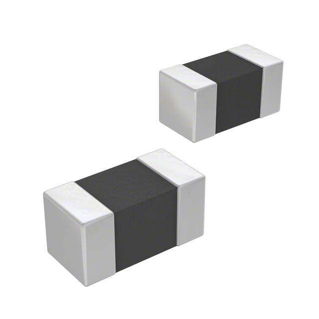
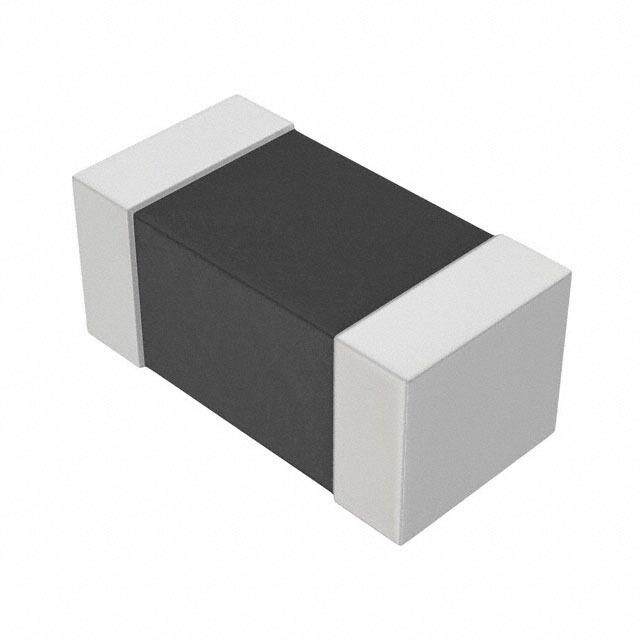
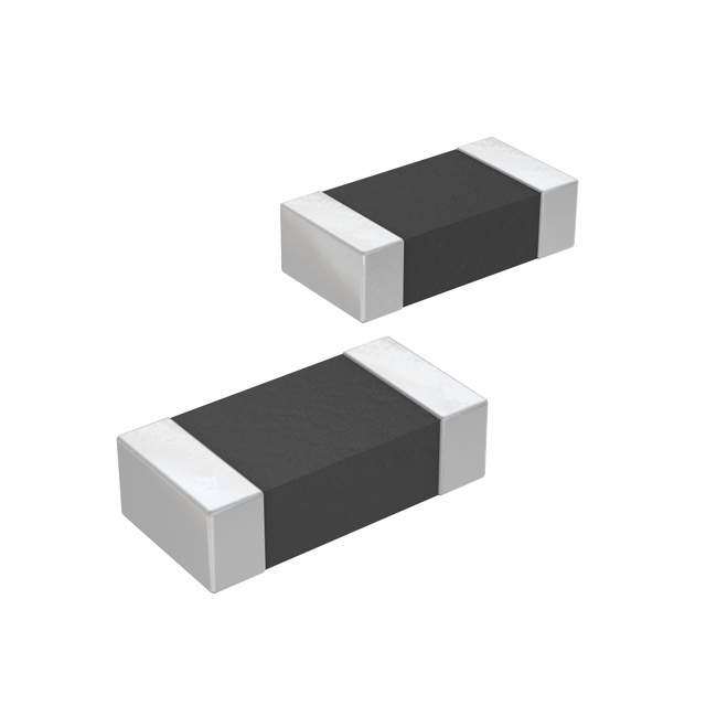
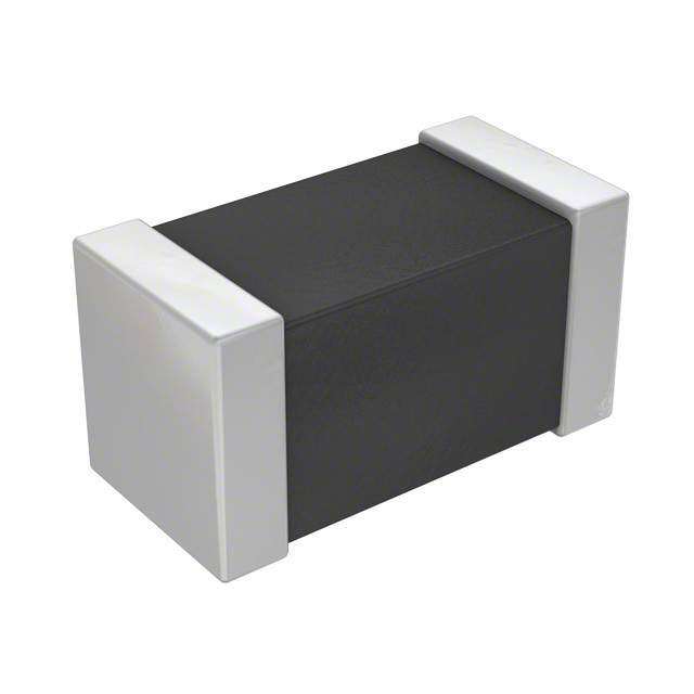
| 描述 | VARISTOR 0402压敏电阻 18VDC 80V-CLAMP 9PF |
| 产品分类 | |
| 品牌 | Bourns |
| 产品手册 | |
| 产品图片 |
|
| rohs | 过渡期间无铅 / 符合限制有害物质指令(RoHS)规范要求 |
| 产品系列 | Bourns CG0402MLE-18GChipGuard® |
| mouser_ship_limit | 该产品可能需要其他文档才能发货到中国。 |
| 数据手册 | |
| 产品型号 | CG0402MLE-18G |
| RoHS指令信息 | |
| 产品 | MLV |
| 产品种类 | 压敏电阻 |
| 其它名称 | CG0402MLE-18GCT |
| 包装 | 带卷 (TR) |
| 变阻器电压 | - |
| 商标 | Bourns |
| 商标名 | ChipGuard |
| 外壳代码-in | 0402 |
| 外壳代码-mm | 1005 |
| 外壳宽度 | 0.5 mm |
| 安装 | SMD/SMT |
| 宽度 | 0.5 mm |
| 封装 | Reel |
| 封装/外壳 | 0402(1005 公制) |
| 封装/箱体 | 0402 (1005 metric) |
| 尺寸 | 0.5 mm W x 1 mm L x 0.5 mm H |
| 峰值浪涌电流 | 30 A |
| 工作温度范围 | - 55 C to + 125 C |
| 工作电压 | 18 V |
| 工厂包装数量 | 10000 |
| 最大AC电压 | 8.5VAC |
| 最大DC电压 | 18VDC |
| 标准包装 | 1 |
| 电压 | 18 V |
| 电压额定值AC | 8.5 V |
| 电压额定值DC | 18 V |
| 电容 | 9 pF |
| 电流-浪涌 | - |
| 电流额定值 | 10 uA |
| 电路数 | 1 |
| 端接类型 | SMD/SMT |
| 系列 | MLE |
| 能量 | - |
| 通道 | 1 Channel |
| 钳位电压 | 120 V |


- 商务部:美国ITC正式对集成电路等产品启动337调查
- 曝三星4nm工艺存在良率问题 高通将骁龙8 Gen1或转产台积电
- 太阳诱电将投资9.5亿元在常州建新厂生产MLCC 预计2023年完工
- 英特尔发布欧洲新工厂建设计划 深化IDM 2.0 战略
- 台积电先进制程称霸业界 有大客户加持明年业绩稳了
- 达到5530亿美元!SIA预计今年全球半导体销售额将创下新高
- 英特尔拟将自动驾驶子公司Mobileye上市 估值或超500亿美元
- 三星加码芯片和SET,合并消费电子和移动部门,撤换高东真等 CEO
- 三星电子宣布重大人事变动 还合并消费电子和移动部门
- 海关总署:前11个月进口集成电路产品价值2.52万亿元 增长14.8%

PDF Datasheet 数据手册内容提取
Features NT MPLIA ■ 0402 and 0603 package options HS CO ■ Rated for IEC 61000-4-2, for applications requiring up to 18 V DC *Ro ■ Withstands multiple ESD strikes ■ Low capacitance and leakage currents for invisible load protection ■ Tape and reel packaging ChipGuard® MLE Series Varistor ESD Clamp Protectors Description The ChipGuard® CG0402MLE and CG0603MLE Series have been designed to provide high frequency attenuation, thereby providing suppression and fi ltering in a single device. The MLE family also offers protection to ESD standards such as IEC61000-4-2 for applications requiring up to 18 V DC and is available in the industry standard 0603 and 0402 type leadless surface mount packaging. Electrical Characteristics @ 25 °C (unless otherwise noted) Continuous Clamping Off-state Current Capacitance Operating Voltage Voltage Vrms VDC VCLAMP IL CP Model (V) (V) (V) (µA) (pF) Max. Typ. Max. Typ. Max. Max. 1 A 1 Vrms 3.5 V 5.5 V 9 V 12 V 18 V @ 8/20 µs @ 1 MHz CG0402MLE-18G 8.5 12 18 100 0.3 0.4 0.5 1 10 9 CG0603MLE-18E 8.5 12 18 60 0.3 0.4 0.5 1 10 50 Environmental Characteristics Surge Withstand Ratings Operating Temperature ...-55 °C to +125 °C Peak Current Peak Current Storage Temperature.......-55 °C to +125 °C Model 8/20 µs @ 8 kV Response Time..................................<1 ns (Max.) (Max.) Standard .................IEC 61000-4-2 Level 4 CG0402MLE-18G 15 A 30 A These products are RoHS compliant. CG0603MLE-18E 20 A 45 A There is some lead contained within the glass of the ceramic. This is acceptable under exemption no. 5 of the RoHS Voltage-Current Characteristics directive (DIRECTIVE 2002/95/EC OF THE EUROPEAN PARLIAMENT AND OF THE COUNCIL of 27 January 2003 on the restriction of the use of certain hazardous 2 10 substances in electrical and electronic equipment). CG0402MLE-18G CG0603MLE-18E Schematic CG0402MLE-18G olts) CG0603MLE-18E V e ( 101 g a olt V 0 *RoHS Directive 2002/95/EC Jan. 27, 2003 including 10 annex and RoHS Recast 2011/65/EU June 8, 2011. 10-8 10-7 10-6 10-5 10-4 10-3 10-2 10-1 100 101 102 103 104 Specifi cations are subject to change without notice. The device characteristics and parameters in this data SOURCE = DC SOURCE = 8/20 μs PULSE, IPEAK sheet can and do vary in different applications and actual device performance may vary over time. I Current (Amps) Users should verify actual device performance in their specifi c applications.
3Ch3i1p2G u-a 2rd m® mML SE MSeDr iTesri Vmamrisitnogr EPSoDte Cnlatimomp Pertoetrectors Product Dimensions Recommended Pad Layout A A W MM DIMENSIONS: (INCHES) B L C B D CG0402MLE CG0603MLE CG0402MLE CG0603MLE Dimension Series Series Dim. Series Series 1.00 ± 0.15 1.60 ± 0.20 0.51 0.76 L A (0.04 ± 0.006) (0.064 ± 0.008) (0.020) (0.030) 0.50 ± 0.10 0.80 ± 0.20 0.61 1.02 W B (0.02 ± 0.004) (0.032 ± 0.008) (0.024) (0.040) 0.50 ± 0.10 0.80 ± 0.20 0.51 0.50 A C (0.02 ± 0.004) (0.032 ± 0.008) (0.020) (0.020) 0.25 ± 0.15 0.30 ± 0.20 1.70 2.54 B D (0.10 ± 0.006) (0.012 ± 0.008) (0.067) (0.100) Solder Refl ow Recommendations Preheat Stages 1-3 Soldering Cooling A Stage 1 Preheat Ambient to Preheating 30 s to 60 s 300 Temperature 250 B Stage 2 Preheat 140 °C to 160 °C 60 s to 120 s mperature (C)° 211050000 CD SM taaigne H 3e aPtrienhge at 22P01re00h °°eCCa t to 200 °C 652050 sss tttooo 764050 sss Te 220 °C 50 s to 60 s 50 230 °C 40 s to 50 s 240 °C 30 s to 40 s 0 E Cooling 200 °C to 100 °C 1 °C/s to 4 °C/s 110 sec. (min.) 30-70 120 sec. (min.) sec. Time (seconds) • This product can be damaged by rapid heating, cooling or localized heating. • Heat shocks should be avoided. Preheating and gradual cooling recommended. • Excessive solder can damage the device. Print solder thickness of 150 to 200 um recommended. • Solder gun tip temperature should be kept below 280 °C and should not touch the device directly. Contact should be less than 3 seconds. A solder gun under 30 watts is recommended. How to Order CG 0n0n MLE - 18 x ChipGuard® Product Designator Package Option 0402 = 0402 Package 0603 = 0603 Package Multilayer Series Designator Operating Voltage 18 = 18 V Tape & Reel Packaging E = 4,000 pcs. per reel (0603 package) G = 10,000 pcs. per reel (0402 package) Ni barrier terminations are standard on all ChipGuard® part numbers. Specifi cations are subject to change without notice. Customers should verify actual device performance in their specifi c applications.
ChipGuard® MLE Series Varistor ESD Clamp Protectors Packaging Dimensions 13.0 ± 1.0 8.00 ± 0.30 (0.52 ± 0.04) (0.32 ± 0.012) 4.00 ± 0.10 (0.16 ± 0.004) 1.50 ± 0.10 C (0.06 ± 0.004) 2.0 ± 0.50 (622.4.08 ±± 10..5006) (0.08 ± 0.02) L 13.0 ± 0.50 (0.52 ± 0.02) TOP G D TAPE 21.0 ± 0.80 3.50 ± 0.05 (0.84 ± 0.032) 180.8 ± 2.0 W (0.14 ± 0.002) (7.12 ± 0.08) NOTES: TAPE MATERIAL IS PAPER. 0.48 ± 0.03 TAPE THICKNESS IS(0.019 ± 0.0012) DIMENSIONS: MM COVER TAPE ADHESION IS 40 ± 15 GRAMS. (INCHES) 9.0 ± 0.50 (0.36 ± 0.02) CG0402MLE CG0603MLE Dimension Series Series 1.75 ± 0.05 1.75 ± 0.10 C (0.04 ± 0.002) (0.04 ± 0.004) 2.00 ± 0.02 2.00 ± 0.05 D (0.08 ± 0.0008) (0.08 ± 0.002) 1.19 ± 0.05 1.80 ± 0.20 L (0.047 ± 0.002) (0.072 ± 0.008) 0.69 ± 0.05 0.90 ± 0.20 W (0.027 ± 0.002) (0.036 ± 0.008) 2.0 ± 0.05 4.0 ± 0.05 G (0.08 ± 0.002) (0.16 ± 0.002) Asia-Pacifi c: Tel: +886-2 2562-4117 • Fax: +886-2 2562-4116 Europe: Tel: +41-41 768 5555 • Fax: +41-41 768 5510 The Americas: Tel: +1-951 781-5500 • Fax: +1-951 781-5700 www.bourns.com REV. I 09/12 Specifi cations are subject to change without notice. Customers should verify actual device performance in their specifi c applications.